US5689397A - Arrangement for disconnecting branches of a low voltage supply network under short circuit conditions - Google Patents
Arrangement for disconnecting branches of a low voltage supply network under short circuit conditions Download PDFInfo
- Publication number
- US5689397A US5689397A US08/525,676 US52567695A US5689397A US 5689397 A US5689397 A US 5689397A US 52567695 A US52567695 A US 52567695A US 5689397 A US5689397 A US 5689397A
- Authority
- US
- United States
- Prior art keywords
- circuit
- bridging
- breaker
- switch
- neutral conductor
- Prior art date
- Legal status (The legal status is an assumption and is not a legal conclusion. Google has not performed a legal analysis and makes no representation as to the accuracy of the status listed.)
- Expired - Fee Related
Links
- 239000004020 conductor Substances 0.000 claims abstract description 50
- 230000007935 neutral effect Effects 0.000 claims abstract description 29
- 239000000463 material Substances 0.000 claims description 7
- 230000005405 multipole Effects 0.000 claims description 7
- 229910044991 metal oxide Inorganic materials 0.000 claims description 2
- 229910052709 silver Inorganic materials 0.000 claims description 2
- 239000004332 silver Substances 0.000 claims description 2
- -1 silver metal-oxide Chemical class 0.000 claims description 2
- OKTJSMMVPCPJKN-UHFFFAOYSA-N Carbon Chemical compound [C] OKTJSMMVPCPJKN-UHFFFAOYSA-N 0.000 claims 2
- 230000008878 coupling Effects 0.000 claims 2
- 238000010168 coupling process Methods 0.000 claims 2
- 238000005859 coupling reaction Methods 0.000 claims 2
- 229910002804 graphite Inorganic materials 0.000 claims 1
- 239000010439 graphite Substances 0.000 claims 1
- 230000001681 protective effect Effects 0.000 description 6
- 239000004065 semiconductor Substances 0.000 description 6
- 238000010586 diagram Methods 0.000 description 5
- 230000000694 effects Effects 0.000 description 2
- 238000010276 construction Methods 0.000 description 1
- 238000010891 electric arc Methods 0.000 description 1
- 230000005520 electrodynamics Effects 0.000 description 1
- 230000005284 excitation Effects 0.000 description 1
- 239000007770 graphite material Substances 0.000 description 1
- 238000012544 monitoring process Methods 0.000 description 1
- 238000000926 separation method Methods 0.000 description 1
Images


Classifications
-
- H—ELECTRICITY
- H02—GENERATION; CONVERSION OR DISTRIBUTION OF ELECTRIC POWER
- H02H—EMERGENCY PROTECTIVE CIRCUIT ARRANGEMENTS
- H02H3/00—Emergency protective circuit arrangements for automatic disconnection directly responsive to an undesired change from normal electric working condition with or without subsequent reconnection ; integrated protection
- H02H3/02—Details
- H02H3/021—Details concerning the disconnection itself, e.g. at a particular instant, particularly at zero value of current, disconnection in a predetermined order
- H02H3/023—Details concerning the disconnection itself, e.g. at a particular instant, particularly at zero value of current, disconnection in a predetermined order by short-circuiting
Definitions
- the present invention relates generally to apparatuses for disconnecting branches of a low voltage supply network under short circuit conditions, and more particularly to an apparatus for disconnecting branches of a low voltage supply network under short circuit conditions, in which power consumers are connected in the branch to phase conductors and to a corresponding neutral conductor, a switching element is connected in the incoming circuit to the consumer in order to switch it on and/or off, and switching elements for short-circuit breaking being provided in the phase conductor and/or the neutral conductor, to which switching elements a bridging circuit with a switching contact is connected, and in which a single circuit-breaker is also provided in the phase conductor.
- German A-40 40 359 describes a hybrid bridging device, which limits the Joulean heat integral to about 1/20 of the value of current-limiting line safety switches on the load side of the protective circuit.
- This very high protective action is necessary when using semiconductor switches in low-voltage branches, for example to control consumers, since overload currents of a short duration must not exceed ten times the value of the rated current in order not to destroy the semiconductor.
- this requires considerable outlay for equipment, since the hybrid bridging device needs a semiconductor switch with a higher rated current and a current-detecting and driving device.
- EP-A-0 504 463 proposes bridging low-voltage branches, where the circuit-breaker is provided with a tap of the arc chute and the switching arc starts up the bridging.
- the short-circuit protection depends on the operating speed of the switch mechanism and on the transit speed of the switching arc. Therefore, only a relatively small reduction in the Joulean heat integral is achieved on the load side of the protective device, which amounts more or less to half of the pass-through Joulean heat integral.
- German A-41 10 335 discloses a device for short-circuit protection, in which is connected a semiconductor switch in incoming circuit to the sensitive consumer, and the semiconductor switch connected in series to a mechanical switch and contains a bridging branch circuit leading to the neutral conductor.
- the bridging branch circuit is thereby provided with a bridging switch, which is switched on instantaneously by the short-circuit current and bridges the consumer and an additional circuit-breaker.
- U.S. Pat. No. 2,924,752 discloses an arrangement for disconnecting three-phase low-voltage supply networks using a three-pole circuit breaker, in which a bridging circuit with a bridging current branch is provided, by way of which a part of the short-circuit current is conducted past the magnetic drive via switching contacts. Due to the special design of the bridging current branch, this arrangement is intended exclusively for multipole networks.
- the present invention is therefore directed to an apparatus for providing short-circuit protection, which will greatly limit the short-circuit current and the short-circuit duration in sensitive electrical devices, and which will have a simpler construction.
- the present invention solves this problem by providing only one single circuit-breaker in the phase conductor, and by disposing the bridging circuit on the load side of the single circuit-breaker, and by providing a magnetically driven switching contact closing a bridging current branch leading to the neutral conductor.
- the bridging current branch has a resistor whose resistance value amounts to between 25% and 50% of the value of the smallest load-circuit impedance to be expected.
- the bridging circuit conducts part of the short-circuit current through the switching contact.
- the arrangement according to the present invention is simplified compared to existing prior art arrangements.
- a bridging contact is present, through which the short-circuiting current is directed to the neutral conductor, without an additional switch being required; the resistor, whose resistance value amounts to about 1/4 to 1/2 of the value of the smallest load-circuit impedance to be expected, being provided to limit the short-circuiting current in the bridging branch.
- the circuit-breaker and the bridging branch can advantageously form one unit.
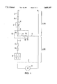
- FIG. 1 depicts a circuit diagram of an example of a bridging circuit according to an embodiment of the present invention.
- FIG. 2 depicts a circuit diagram of a common protection device formed by integrating the circuit-breaker and the bridging device.
- FIG. 3 shows a circuit diagram of another embodiment of FIG. 2 illustrating different connecting points for the slide rails.
- FIG. 4 shows a circuit diagram of another embodiment of FIG. 2 in which the magnetic drives are configured in the load circuit.
- FIG. 5 depicts a circuit diagram of another embodiment of FIG. 3 in which the magnetic drives are configured in the load circuit.
- FIG. 1 shows a single-phase electrical network having an impedance L 1 , R 1 on the incoming supply side of a circuit-breaker 1, which, on the load side, has a bridging circuit 10, as well as a short-circuit impedance L 2 , R 2 , which leads to a sensitive system part formed by a contactor 8 and a consumer 9, e.g., a motor.
- a bridging circuit 10 Connected up on the load side of the circuit-breaker 1 comprising the connecting points A and B, is a bridging circuit 10, which has a switch 11 constituting the actual bridging contact, a corresponding magnetic drive 12, and a bridging current branch 13 comprising the resistor 14.
- the bridging current branch 13 is connected to point D
- the bridging circuit 10 has the connecting point C leading to the contactor 8, and has the connecting point D connected to the neutral conductor.
- a circuit arrangement of this type can also be designed for multiphase wiring systems, so that a multipole monitoring circuit is used.
- the magnetic drive of the bridging device can be so rated that, given dead short-circuits of I prosp . of 3 to 6 kA, response times of about 1.2 to 0.8 ms are reached for the magnetic drive.
- the rapid removal of load from the load circuit by means of the bridging circuit 10 leads in this case to a I 2 .t load, which now amounts to about 1/5 to 1/10 of the pass-through I 2 .t value of the line safety switch.
- the circuit-breaker 1 is comprised of an arc chute with arc chute plates 3 and slide rails 4, a corresponding switch 5, a thermal trip element 6 and a magnetic drive 7.
- the broken line indicates the common protective device formed by integrating the circuit-breaker 1 and the bridging device 10.
- FIG. 3 indicates another embodiment of FIG. 2 in which the connecting points of the slide rails 4 permit the arc chute 2 to bridge the circuit-breaker contact 5, the thermal trip element 6, and the magnetic trip element 7, as well as the magnetic drive 12 and the corresponding switch 11.
- the magnetic drive 12 of the bridging device 10 After commutation of the arc into the arc chute 2, the magnetic drive 12 of the bridging device 10, inter alia, becomes currentless and the switch 11, with its switching voltage, interrupts the load current relatively early.
- the switching contact of the switch 11 normally switches free of arcs.
- an arc loading occurs at the switching contact of switch 11, which has to be taken into consideration when designing the contact members used here.
- FIGS. 4 and 5 illustrate an embodiment in which the protective devices differ from those of FIGS. 2 and 3 essentially in that the magnetic drives 7 and 12 are configured in the load circuit instead of in the supply circuit. To this end, the magnetic drives 7 and 12 no longer need to be rated for full short-circuit loading.
- the arrangement according to FIG. 5 is especially advantageous, because after load is removed from the switch 11 as the result of electric arc commutation into the arc chute 2, its switching contact remains closed for as long as the magnetic excitation of the magnetic drives 7 and 12 persists due to the load current. Therefore, the switch 11 opens the switching contact free of electric arcs after the load current has decayed.
- FIGS. 2 through 5 can be modified in various details.
- the arrangement of the thermal trip element 6 can be placed between the terminal connection C and the connecting point of the bridging branch.
- the magnetic drives 7 and 12 can be replaced by a common magnetic drive for tripping and bridging.
- the individual connections are connected to one another, respectively, and to the neutral conductor.
- the connection of the terminal connections D take place in the unit.
- contact members of weld-resistant contact materials are used for the switching contact of the switch 11.
- Possible materials for this are materials on a silver metal-oxide (AgMeO) base, such as the known AgSnO 2 8, or silver- or copper-graphite materials, such as, for example, AgC5 or CuC7.
- AgMeO silver metal-oxide
- CuC7 silver- or copper-graphite materials
Landscapes
- Arc-Extinguishing Devices That Are Switches (AREA)
- Emergency Protection Circuit Devices (AREA)
Applications Claiming Priority (3)
| Application Number | Priority Date | Filing Date | Title |
|---|---|---|---|
| DE4309794A DE4309794A1 (de) | 1993-03-25 | 1993-03-25 | Anordnung zur Freischaltung von Abzweigen eines Niederspannungs-Leitungsnetzes im Kurzschlußfall |
| DE4309794.4 | 1993-03-25 | ||
| PCT/DE1994/000296 WO1994022197A1 (de) | 1993-03-25 | 1994-03-17 | Anordnung zur freischaltung von abzweigen eines niederspannungs-leitungsnetzes im kurzschlussfall |
Publications (1)
| Publication Number | Publication Date |
|---|---|
| US5689397A true US5689397A (en) | 1997-11-18 |
Family
ID=6483886
Family Applications (1)
| Application Number | Title | Priority Date | Filing Date |
|---|---|---|---|
| US08/525,676 Expired - Fee Related US5689397A (en) | 1993-03-25 | 1994-03-17 | Arrangement for disconnecting branches of a low voltage supply network under short circuit conditions |
Country Status (5)
| Country | Link |
|---|---|
| US (1) | US5689397A (de) |
| EP (1) | EP0691046B1 (de) |
| JP (1) | JP3456996B2 (de) |
| DE (2) | DE4309794A1 (de) |
| WO (1) | WO1994022197A1 (de) |
Cited By (7)
| Publication number | Priority date | Publication date | Assignee | Title |
|---|---|---|---|---|
| WO2000007205A1 (de) * | 1998-07-30 | 2000-02-10 | Siemens Aktiengesellschaft | Einrichtung zum kurzschlussschutz |
| US6823020B1 (en) * | 1998-03-19 | 2004-11-23 | Conti Temic Microelectronic Gmbh | Signaling output stage for generating digital voltage signals on a bus system |
| US20070035903A1 (en) * | 2004-12-30 | 2007-02-15 | Inpower Llc | Control and operating condition monitoring of dual series switch contactors for electric motor or other electrical load |
| US20080186643A1 (en) * | 2007-02-01 | 2008-08-07 | Schneider Electric Industries Sas | Voltage surge protection device with a movable contact comprising selective disconnection means against short-circuits |
| US20110110006A1 (en) * | 2008-06-27 | 2011-05-12 | Siemens Aktiengesellschaft | Method for selectively triggering circuit breakers in the event of a short circuit |
| WO2011116832A1 (en) * | 2010-03-26 | 2011-09-29 | Abb Research Ltd | A hybrid circuit breaker |
| US20230411955A1 (en) * | 2020-11-24 | 2023-12-21 | Gridon Ltd | Current sinking arrangement |
Families Citing this family (1)
| Publication number | Priority date | Publication date | Assignee | Title |
|---|---|---|---|---|
| KR20260023038A (ko) | 2023-07-25 | 2026-02-20 | 미쓰비시덴키 가부시키가이샤 | 전력 계통 보호 시스템 |
Citations (5)
| Publication number | Priority date | Publication date | Assignee | Title |
|---|---|---|---|---|
| US2924752A (en) * | 1957-07-12 | 1960-02-09 | Ite Circuit Breaker Ltd | Combined circuit breaker and short circuiter |
| US3864604A (en) * | 1972-05-08 | 1975-02-04 | Josef Pfanzelt | Electrical switching device |
| DE4040359A1 (de) * | 1990-12-17 | 1992-07-02 | Siemens Ag | Einrichtung zum kurzschlussschutz |
| EP0504463A1 (de) * | 1991-03-21 | 1992-09-23 | Siemens Aktiengesellschaft | Schaltungsanordnung zur Stromversorgung |
| DE4110335A1 (de) * | 1991-03-28 | 1992-10-01 | Siemens Ag | Einrichtung zum kurzschlussschutz |
-
1993
- 1993-03-25 DE DE4309794A patent/DE4309794A1/de not_active Withdrawn
-
1994
- 1994-03-17 JP JP52051794A patent/JP3456996B2/ja not_active Expired - Fee Related
- 1994-03-17 EP EP94910342A patent/EP0691046B1/de not_active Expired - Lifetime
- 1994-03-17 US US08/525,676 patent/US5689397A/en not_active Expired - Fee Related
- 1994-03-17 WO PCT/DE1994/000296 patent/WO1994022197A1/de not_active Ceased
- 1994-03-17 DE DE59405117T patent/DE59405117D1/de not_active Expired - Fee Related
Patent Citations (5)
| Publication number | Priority date | Publication date | Assignee | Title |
|---|---|---|---|---|
| US2924752A (en) * | 1957-07-12 | 1960-02-09 | Ite Circuit Breaker Ltd | Combined circuit breaker and short circuiter |
| US3864604A (en) * | 1972-05-08 | 1975-02-04 | Josef Pfanzelt | Electrical switching device |
| DE4040359A1 (de) * | 1990-12-17 | 1992-07-02 | Siemens Ag | Einrichtung zum kurzschlussschutz |
| EP0504463A1 (de) * | 1991-03-21 | 1992-09-23 | Siemens Aktiengesellschaft | Schaltungsanordnung zur Stromversorgung |
| DE4110335A1 (de) * | 1991-03-28 | 1992-10-01 | Siemens Ag | Einrichtung zum kurzschlussschutz |
Cited By (12)
| Publication number | Priority date | Publication date | Assignee | Title |
|---|---|---|---|---|
| US6823020B1 (en) * | 1998-03-19 | 2004-11-23 | Conti Temic Microelectronic Gmbh | Signaling output stage for generating digital voltage signals on a bus system |
| WO2000007205A1 (de) * | 1998-07-30 | 2000-02-10 | Siemens Aktiengesellschaft | Einrichtung zum kurzschlussschutz |
| US6441709B2 (en) | 1998-07-30 | 2002-08-27 | Siemens Aktiengesellschaft | Device for short-circuit protection |
| US20070035903A1 (en) * | 2004-12-30 | 2007-02-15 | Inpower Llc | Control and operating condition monitoring of dual series switch contactors for electric motor or other electrical load |
| US7408274B2 (en) * | 2004-12-30 | 2008-08-05 | Inpower Llc | Control and operating condition monitoring of dual series switch contactors for electric motor or other electrical load |
| US20080186643A1 (en) * | 2007-02-01 | 2008-08-07 | Schneider Electric Industries Sas | Voltage surge protection device with a movable contact comprising selective disconnection means against short-circuits |
| US20110110006A1 (en) * | 2008-06-27 | 2011-05-12 | Siemens Aktiengesellschaft | Method for selectively triggering circuit breakers in the event of a short circuit |
| US8503142B2 (en) * | 2008-06-27 | 2013-08-06 | Siemens Aktiengesellschaft | Method for selectively triggering circuit breakers in the event of a short circuit |
| WO2011116832A1 (en) * | 2010-03-26 | 2011-09-29 | Abb Research Ltd | A hybrid circuit breaker |
| US8810985B2 (en) | 2010-03-26 | 2014-08-19 | Abb Research Ltd. | Hybrid circuit breaker |
| US20230411955A1 (en) * | 2020-11-24 | 2023-12-21 | Gridon Ltd | Current sinking arrangement |
| US12308637B2 (en) * | 2020-11-24 | 2025-05-20 | Gridon Ltd | Current sinking arrangement |
Also Published As
| Publication number | Publication date |
|---|---|
| JPH08508154A (ja) | 1996-08-27 |
| DE59405117D1 (de) | 1998-02-26 |
| DE4309794A1 (de) | 1994-09-29 |
| JP3456996B2 (ja) | 2003-10-14 |
| EP0691046A1 (de) | 1996-01-10 |
| WO1994022197A1 (de) | 1994-09-29 |
| EP0691046B1 (de) | 1998-01-21 |
Similar Documents
| Publication | Publication Date | Title |
|---|---|---|
| KR101483298B1 (ko) | 모터 시동기 | |
| CA2166225C (en) | Circuit breaker and circuit breaking apparatus | |
| JP4596895B2 (ja) | モジュラー型接触器装置の複数の接触器をそれぞれ独立に制御するコントローラ | |
| US4950973A (en) | Permanent magnet generator system | |
| CN109997208B (zh) | 低压断路器装置 | |
| CN111433875B (zh) | 低压保护开关设备 | |
| US6710988B1 (en) | Small-sized industrial rated electric motor starter switch unit | |
| US5247419A (en) | Low voltage switchgear | |
| CN100524562C (zh) | 带有熔断器的开关保护装置 | |
| JP3456996B2 (ja) | 短絡時に低圧回路網の枝路を切り離すための装置 | |
| US6441709B2 (en) | Device for short-circuit protection | |
| EP1309059A2 (de) | Automatischer Spannungswähler für Schutzschalter mit Elektronik | |
| US5617281A (en) | Low cost circuit controller | |
| US4794362A (en) | Alternating current power circuit and fuse therefor | |
| JPH1031924A (ja) | 複合型スイッチング装置 | |
| JP3423539B2 (ja) | 高速再閉路装置 | |
| JPH0757594A (ja) | 電気負荷の防護/制御装置 | |
| SU1647746A1 (ru) | Устройство дл защиты трехфазного электродвигател от работы на двух фазах | |
| US20250182992A1 (en) | Modular electrical protection device with control and power modules | |
| JP2001095151A (ja) | 事故電流を抑制可能な直接接地システム | |
| JP2603662B2 (ja) | 回路保護器 | |
| JP2784142B2 (ja) | 遮断器および遮断装置 | |
| SU1171900A1 (ru) | Устройство дл защиты трехфазного электродвигател от анормального режима | |
| SU1394319A1 (ru) | Устройство дл защиты асинхронного электродвигател от анормальных режимов работы | |
| US3327168A (en) | Dual-element motor controller |
Legal Events
| Date | Code | Title | Description |
|---|---|---|---|
| AS | Assignment |
Owner name: SIEMENS AKTIENGELSELLSCHAFT, GERMANY Free format text: ASSIGNMENT OF ASSIGNORS INTEREST;ASSIGNORS:POHL, FRITZ;JAEHNER, WILFRIED;REEL/FRAME:007990/0210 Effective date: 19940315 |
|
| FEPP | Fee payment procedure |
Free format text: PAYOR NUMBER ASSIGNED (ORIGINAL EVENT CODE: ASPN); ENTITY STATUS OF PATENT OWNER: LARGE ENTITY |
|
| FPAY | Fee payment |
Year of fee payment: 4 |
|
| FPAY | Fee payment |
Year of fee payment: 8 |
|
| REMI | Maintenance fee reminder mailed | ||
| LAPS | Lapse for failure to pay maintenance fees | ||
| STCH | Information on status: patent discontinuation |
Free format text: PATENT EXPIRED DUE TO NONPAYMENT OF MAINTENANCE FEES UNDER 37 CFR 1.362 |
|
| FP | Lapsed due to failure to pay maintenance fee |
Effective date: 20091118 |