EP0691046B1 - Arrangement for disconnecting branches of a low voltage supply network under short circuit conditions - Google Patents
Arrangement for disconnecting branches of a low voltage supply network under short circuit conditions Download PDFInfo
- Publication number
- EP0691046B1 EP0691046B1 EP94910342A EP94910342A EP0691046B1 EP 0691046 B1 EP0691046 B1 EP 0691046B1 EP 94910342 A EP94910342 A EP 94910342A EP 94910342 A EP94910342 A EP 94910342A EP 0691046 B1 EP0691046 B1 EP 0691046B1
- Authority
- EP
- European Patent Office
- Prior art keywords
- circuit
- bridging
- breaker
- arrangement according
- switch
- Prior art date
- Legal status (The legal status is an assumption and is not a legal conclusion. Google has not performed a legal analysis and makes no representation as to the accuracy of the status listed.)
- Expired - Lifetime
Links
- 239000004020 conductor Substances 0.000 claims abstract description 24
- 230000007935 neutral effect Effects 0.000 claims abstract description 14
- 238000011144 upstream manufacturing Methods 0.000 claims abstract description 4
- 239000000463 material Substances 0.000 claims description 5
- 230000007246 mechanism Effects 0.000 claims description 4
- BQCADISMDOOEFD-UHFFFAOYSA-N Silver Chemical compound [Ag] BQCADISMDOOEFD-UHFFFAOYSA-N 0.000 claims description 3
- 229910044991 metal oxide Inorganic materials 0.000 claims description 2
- OKTJSMMVPCPJKN-UHFFFAOYSA-N Carbon Chemical compound [C] OKTJSMMVPCPJKN-UHFFFAOYSA-N 0.000 claims 4
- RYGMFSIKBFXOCR-UHFFFAOYSA-N Copper Chemical compound [Cu] RYGMFSIKBFXOCR-UHFFFAOYSA-N 0.000 claims 1
- 229910052802 copper Inorganic materials 0.000 claims 1
- 239000010949 copper Substances 0.000 claims 1
- 229910002804 graphite Inorganic materials 0.000 claims 1
- 239000010439 graphite Substances 0.000 claims 1
- 230000001681 protective effect Effects 0.000 description 6
- 239000004065 semiconductor Substances 0.000 description 5
- 230000005405 multipole Effects 0.000 description 3
- 230000004913 activation Effects 0.000 description 2
- 230000000694 effects Effects 0.000 description 2
- 230000010354 integration Effects 0.000 description 2
- 238000001514 detection method Methods 0.000 description 1
- 230000005611 electricity Effects 0.000 description 1
- 230000005284 excitation Effects 0.000 description 1
- 239000007770 graphite material Substances 0.000 description 1
- 230000008018 melting Effects 0.000 description 1
- 238000002844 melting Methods 0.000 description 1
- 238000012544 monitoring process Methods 0.000 description 1
- 238000010791 quenching Methods 0.000 description 1
- 230000000171 quenching effect Effects 0.000 description 1
- 230000009467 reduction Effects 0.000 description 1
- 230000004044 response Effects 0.000 description 1
- 229920006395 saturated elastomer Polymers 0.000 description 1
- 229910052709 silver Inorganic materials 0.000 description 1
- 239000004332 silver Substances 0.000 description 1
Images

Classifications
-
- H—ELECTRICITY
- H02—GENERATION; CONVERSION OR DISTRIBUTION OF ELECTRIC POWER
- H02H—EMERGENCY PROTECTIVE CIRCUIT ARRANGEMENTS
- H02H3/00—Emergency protective circuit arrangements for automatic disconnection directly responsive to an undesired change from normal electric working condition with or without subsequent reconnection ; integrated protection
- H02H3/02—Details
- H02H3/021—Details concerning the disconnection itself, e.g. at a particular instant, particularly at zero value of current, disconnection in a predetermined order
- H02H3/023—Details concerning the disconnection itself, e.g. at a particular instant, particularly at zero value of current, disconnection in a predetermined order by short-circuiting
Definitions
- the invention relates to an arrangement for activation of branches of a low-voltage network in the event of a short circuit, in the consumer branch connected to the phase conductor and an associated neutral conductor are, with the consumer a switching element for and / or switching upstream and in the phase conductor and / or neutral conductor additional switching elements for short-circuit switching are provided to which a bypass circuit is switched on with switch, in Phase conductor a single circuit breaker is present.
- EP-A-0 504 463 Bridging low voltage feeders proposed in which the circuit breaker with a tap of the Extinguishing plate chamber is provided and the switching arc Bridging switches on.
- the short-circuit protection depends on this on the switching speed of the switch mechanism and on the running speed of the switching arc. It is therefore only a relatively small reduction in the electricity heat integral reached on the load side of the protective device, which is about half of the forward current heat integral is.
- From DE-A-41 10 335 is a device for Short-circuit protection known to the sensitive consumer in particular a semiconductor switch upstream is connected in series with a mechanical switch and a bridging current branch to the neutral conductor contains.
- the bridging current branch is with a Bypass switch provided by the short circuit current is switched on without delay and the consumer and bridged an additional circuit breaker.
- the object is achieved in that on the bridging circuit on the load side of the single circuit breaker part of the short-circuit current on Switch passed by, being in the bypass circuit there is a bridging current branch with resistance, whose resistance value is between 25 and 50% of the value oer smallest expected load circuit impedance is and via the magnetically driven switch on the neutral conductor connected.
- the arrangement according to the invention is therefore opposite State of the art simplified. At the bridging contact is therefore an essential part of the short-circuit current Neutral conductor is passed by. Advantageously the bridging branch now forms together with the Circuit breaker one unit.
- FIG. 1 shows a single-phase electrical network with an impedance L 1 , R 1 on the feed-in side of a circuit breaker, which has a bypass circuit on the load side and a short-circuit impedance L 2 , R 2 , which leads to a sensitive system part with a consumer.
- L 1 , R 1 on the feed-in side of a circuit breaker, which has a bypass circuit on the load side and a short-circuit impedance L 2 , R 2 , which leads to a sensitive system part with a consumer.
- the circuit breaker already mentioned, 8 a contactor and 9 a motor as a consumer, contactor 8 and motor 9 forming a sensitive system part.
- bypass circuit 10 On the load side of the circuit breaker 1 with the connection points A and B is a bypass circuit 10 connected from one, the actual bypass contact forming switch 11, an associated Magnet drive 12 and a bridging current branch 13 with resistor 14.
- the bypass branch 13 is over components 11, 12 and 13 at point B. switched on and has a connection point C to contactor 8 and a connection point C to the neutral conductor.
- a corresponding circuit is also available on multi-phase line systems can be designed so that a multi-pole monitoring circuit is realized.
- the magnetic drive of the bridging device can be designed using FIG. 1 so that in the event of saturated short circuits of I prosp. 3 to 6 kA response times of the magnetic drive of about 1.2 to 0.8 ms can be achieved.
- the rapid relief of the load circuit by the bypass circuit 10 leads to an I 2 .t load, which is now about 1/5 to 1/10 of the forward I 2 .t value of the circuit breaker.
- the circuit breaker 1 is shown in FIGS Figure 1 in detail from an arc chamber with quenching plates 3 and rails 4, an associated switch 5, a thermal release 6 and a magnetic drive 7 formed.
- the dashed line always outputs that the integration of the circuit breaker 1 and the bridging device 10 common protective device formed on.
- the magnetic drive 12 Bridging device 10 de-energized and the switch 11 interrupts relatively early with its switching voltage the load current.
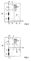
- the protective device differs from that of Figure 2 essentially by the arrangement the magnetic drives 7 and 12 in the load circuit instead of in the feed circuit.
- the magnetic drives 7 and 12 need this no longer designed for the full short-circuit load will.
- the arrangement according to FIG. 3 is therefore special advantageous because after the current relief of the switch 11 through the arc commutation into the switching chamber 2 whose switch-on contact remains closed as long as the magnetic excitation of the magnetic drives 7 and 12 by stops the load current.
- the switch 11 opens the switch-on contact therefore free of arcing after the decay of the Load current.
- connection C the connection point of the Bridging branch.
- the magnetic drives 7 and 12 can by a common magnetic drive for triggering and bridging are replaced.
- bypass circuit can be designed with multiple poles the individual connections are to be connected or connected to the neutral conductor. With an integrated Set up as a multi-pole bypass switch the connection of connections D in the device.
Landscapes
- Arc-Extinguishing Devices That Are Switches (AREA)
- Emergency Protection Circuit Devices (AREA)
Abstract
Description
Die Erfindung bezieht sich auf eine Anordnung zur Freischaltung von Abzweigen eines Niederspannungs-Leitungsnetzes im Kurzschlußfall, bei dem im Abzweig Verbraucher an Phasenleiter und einen zugehörigen Nulleiter geschaltet sind, wobei dem Verbraucher ein Schaltelement zum Ein- und/oder Ausschalten vorgeschaltet ist und im Phasenleiter und/oder Nulleiter zusätzlich Schaltelemente zur Kurzschlußschaltung vorgesehen sind, an die eine Überbrückungsschaltung mit Schalter angeschaltet ist, wobei im Phasenleiter ein einziger Leistungsschalter vorhanden ist.The invention relates to an arrangement for activation of branches of a low-voltage network in the event of a short circuit, in the consumer branch connected to the phase conductor and an associated neutral conductor are, with the consumer a switching element for and / or switching upstream and in the phase conductor and / or neutral conductor additional switching elements for short-circuit switching are provided to which a bypass circuit is switched on with switch, in Phase conductor a single circuit breaker is present.
Zum Kurzschlußschutz von Niederspannungs-Abzweigungen werden üblicherweise strombegrenzende Leistungsschalter oder Leitungsschutzschalter eingesetzt. Die Schaltgeräte begrenzen die Durchlaßströme auf typisch 1/3 bis 1/2 der Stromamplitude des prospektiven Kurzschlußstromes. Für empfindliche elektrische Einrichtungen, beispielsweise Schütze bzw. Relais, sind die Kurzschlußauswirkungen derart hoher Durchlaßströme jedoch nicht tolerierbar. So können Schütz- oder Relaiskontakte durch Stromkräfte bei hohen Strömen dynamisch öffnen und infolge der Kontaktaufschmelzung durch Lichtbögen beim Wiederschließen verschweißen.For short-circuit protection of low-voltage branches usually current limiting circuit breakers or Miniature circuit breaker used. Limit the switching devices the forward currents to typically 1/3 to 1/2 of Current amplitude of the prospective short-circuit current. For sensitive electrical equipment, for example Contactors or relays, the short-circuit effects are such however, high forward currents cannot be tolerated. So can contactor or relay contacts by current forces open high currents dynamically and as a result of contact melting weld by arcing when reclosing.
Vom Stand der Technik sind bereits verschiedene Möglichkeiten bekannt, durch Überbrückung eines Niederspannungsabzweiges die Kurzschlußauswirkungen auf der Lastseite von Schutzeinrichtungen zu begrenzen. In der DE-A-40 40 359 wird beispielsweise eine Hybrid-Überbrückungseinrichtung beschrieben, welche auf der Lastseite der Schutzschaltung das Stromwärmeintegral auf ca. 1/20 des Wertes strombegrenzender Leitungsschutzschalter begrenzt. Diese sehr hohe Schutzwirkung ist beim Einsatz von Halbleiterschaltern, beispielsweise zum Steuern von Verbrauchern, in Niederspannungsabzweigen notwendig, da kurzzeitige Überströme den zehnfachen Wert des Nennstromes nicht übersteigen dürfen, um den Halbleiter nicht zu zerstören. Der Geräteaufwand ist hierfür jedoch beachtlich, da die Hybrid-Überbrückungseinrichtung einen Halbleiterschalter mit höherem Nennstrom und einer Stromerfassungs- und Ansteuereinrichtung benötigt. Weiterhin wird mit der EP-A-0 504 463 eine Überbrückung von Niederspannungsabzweigen vorgeschlagen, bei welcher der Leistungsschalter mit einem Abgriff der Löschblechkammer versehen ist und der Schaltlichtbogen die Überbrückung einschaltet. Der Kurzschlußschutz hängt hierbei von der Schaltgeschwindigkeit der Schaltermechanik und von der Laufgeschwindigkeit des Schaltlichtbogens ab. Es wird daher nur eine relativ geringe Reduzierung des Stromwärmeintegrals auf der Lastseite der Schutzeinrichtung erreicht, welches etwa die Hälfte des Durchlaß-Stromwärmeintegrales beträgt.Various options are already available from the prior art known, by bridging a low-voltage feeder the short circuit effects on the load side of Limit protective devices. In DE-A-40 40 359 becomes, for example, a hybrid bridging device described on the load side of the protection circuit the current heat integral to approx. 1/20 of the value limiting current Miniature circuit breaker limited. This very high protective effect is when using semiconductor switches, for example to control consumers in low-voltage feeders necessary because of short-term overcurrents must not exceed ten times the nominal current, so as not to destroy the semiconductor. The device effort is remarkable for this, however, because the hybrid bridging device a semiconductor switch with higher Nominal current and a current detection and control device needed. Furthermore, EP-A-0 504 463 Bridging low voltage feeders proposed in which the circuit breaker with a tap of the Extinguishing plate chamber is provided and the switching arc Bridging switches on. The short-circuit protection depends on this on the switching speed of the switch mechanism and on the running speed of the switching arc. It is therefore only a relatively small reduction in the electricity heat integral reached on the load side of the protective device, which is about half of the forward current heat integral is.
Aus der DE-A-41 10 335 ist weiterhin eine Einrichtung zum Kurzschlußschutz bekannt, bei der dem empfindlichen Verbraucher insbesondere ein Halbleiterschalter vorgeschaltet ist, der mit einem mechanischen Schalter in Reihe geschaltet ist und einen Überbrückungsstromzweig zum Nulleiter enthält. Dabei ist der Überbrückungsstromzweig mit einem Überbrückungsschalter versehen, der vom Kurzschlußstrom unverzögert eingeschaltet wird und den Verbraucher und einen zusätzlichen Leistungsschalter überbrückt. Dadurch werden insbesondere der Verbraucher und der empfindliche Halbleiterschalter entlastet, wobei in jedem Fall Leitungsschutzschalter im Phasenleiter und im Nulleiter vorhanden sein müssen, was einen zusätzlichen Aufwand beinhaltet.From DE-A-41 10 335 is a device for Short-circuit protection known to the sensitive consumer in particular a semiconductor switch upstream is connected in series with a mechanical switch and a bridging current branch to the neutral conductor contains. The bridging current branch is with a Bypass switch provided by the short circuit current is switched on without delay and the consumer and bridged an additional circuit breaker. Thereby be particularly the consumer and the sensitive Relieved semiconductor switch, in each case circuit breaker present in the phase conductor and in the neutral conductor must be, which involves an additional effort.
Weiterhin ist aus der US-A-2 924 752 eine Anordnung zur Freischaltung von dreiphasigen Niederspannungs-Leitungsnetzen mit einem dreipoligen Leistungsschalter bekannt, bei dem eine Überbrückungsschaltung mit Überbrückungsstromzweig vorhanden ist, über welchen ein Teil des Kurzschlußstromes am Magnetantrieb vorbei über Einschaltkontakte geleitet wird. Diese Anordnung ist wegen der speziellen Gestaltung des Überbrückungsstromzweiges ausschließlich für mehrpolige Netze vorgesehen.Furthermore, from US-A-2 924 752 an arrangement for Activation of three-phase low-voltage line networks known with a three-pole circuit breaker, in which a bypass circuit with a bridging current branch is present, over which a part of the short-circuit current past the magnetic drive via make contacts is directed. This arrangement is because of the special design of the bridging current branch exclusively intended for multi-pole networks.
Die Aufgabe ist erfindungsgemäß dadurch gelöst, daß auf der Lastseite des einzigen Leistungsschalters die Überbrückungsschaltung einen Teil des Kurzschlußstromes am Schalter vorbeileitet, wobei in der Überbrückungsschaltung ein Überbrückungsstromzweig mit Widerstand vorhanden ist, dessen Widerstandswert zwischen 25 und 50 % des Wertes oer kleinsten zu erwartenden Lastkreisimpedanz beträgt und über den der magnetisch angetriebene Schalter am Nulleiter angeschlossen ist.The object is achieved in that on the bridging circuit on the load side of the single circuit breaker part of the short-circuit current on Switch passed by, being in the bypass circuit there is a bridging current branch with resistance, whose resistance value is between 25 and 50% of the value oer smallest expected load circuit impedance is and via the magnetically driven switch on the neutral conductor connected.
Die erfindungsgemäße Anordnung ist also gegenüber dem Stand der Technik vereinfacht. Am Überbrückungskontakt wird also ein wesentlicher Teil des Kurzschlußstroms zum Nulleiter vorbeigeleitet wird. In vorteilhafter Weise bildet der Überbrückungszweig nunmehr zusammen mit dem Leistungsschalter eine Einheit.The arrangement according to the invention is therefore opposite State of the art simplified. At the bridging contact is therefore an essential part of the short-circuit current Neutral conductor is passed by. Advantageously the bridging branch now forms together with the Circuit breaker one unit.
Weitere Einzelheiten und Vorteile der Erfindung ergeben sich aus der nachfolgenden Figurenbeschreibung von Ausführungsbeispielen anhand der Zeichnung in Verbindung mit den Patentansprüchen. Es zeigen
Figur 1- das Prinzip einer Überbrückungsschaltung zum Kurzschlußschutz empfindlicher Anlagenteile eines Lastkreises und die
Figuren 2 und 3- zwei erfindungsgemäße Möglichkeiten der
Integration des Leistungsschalters und der Überbrückungsschaltung
gemäß
Figur 1 zu einer gemeinsamen Schutzeinrichtung.
- Figure 1
- the principle of a bypass circuit for short-circuit protection of sensitive system parts of a load circuit and the
- Figures 2 and 3
- two possibilities according to the invention of integrating the circuit breaker and the bypass circuit according to FIG. 1 into a common protective device.
In Figur 1 ist ein einphasiges elektrisches Netz mit einer
Impedanz L1, R1 auf der Einspeiseseite eines Leistungsschalters,
der auf der Lastseite eine Überbrückungsschaltung
sowie eine Kurzschlußimpedanz L2, R2 hat, die zu
einem empfindlichen Anlageteil mit einem Verbraucher
führt, dargestellt. Im einzelnen bedeutet in FIG 1 neben
den selbsterklärenoen Buchstabensymbolen 1 der bereits erwähnte
Leistungsschalter, 8 ein Schütz und 9 einen Motor
als Verbraucher, wobei Schütz 8 und Motor 9 ein empfindliches
Anlagenteil bilden.1 shows a single-phase electrical network with an impedance L 1 , R 1 on the feed-in side of a circuit breaker, which has a bypass circuit on the load side and a short-circuit impedance L 2 , R 2 , which leads to a sensitive system part with a consumer. Specifically, in FIG. 1, in addition to the self-
Auf der Lastseite des Leistungsschalters 1 mit den Anschlußpunkten
A und B ist eine Überbrückungsschaltung 10
angeschlossen, die aus einem, den eigentlichen Überbrückungskontakt
bildenden Schalter 11, einem zugehörigen
Magnetantrieb 12 und einem Überbrückungsstromzweig 13
mit Widerstand 14 besteht. Der Überbrückungsstromzweig 13
ist also über die Komponenten 11, 12 und 13 am Punkt B
angeschaltet und hat einen Anschlußpunkt C zum Schütz 8
sowie einen Anschlußpunkt C zum Nulleiter. On the load side of the
Eine entsprechende Schaltung ist auch auf mehrphasige Leitungssysteme auslegbar, so daß dann eine mehrpolige Überwachungsschaltung realisiert wird.A corresponding circuit is also available on multi-phase line systems can be designed so that a multi-pole monitoring circuit is realized.
Anhand Figur 1 kann am Beispiel eines Leitungsschutzes für
16 A Nennstrom der Magnetantrieb der Uberbrückungseinrichtung
so ausgelegt werden, daß bei satten Kurzschlüssen von
Iprosp. 3 bis 6 kA Ansprechzeiten des Magnetantriebes
von etwa 1,2 bis 0,8 ms erreicht werden. Die rasche Entlastung
des Lastkreises durch die Überbrückungsschaltung
10 führt dabei zu einer I2.t-Belastung, die nunmehr etwa
1/5 bis 1/10 des Durchlaß-I2.t-Wertes des Leitungsschutzschalters
beträgt.Using the example of a line protection for 16 A rated current, the magnetic drive of the bridging device can be designed using FIG. 1 so that in the event of saturated short circuits of I prosp. 3 to 6 kA response times of the magnetic drive of about 1.2 to 0.8 ms can be achieved. The rapid relief of the load circuit by the
In den Figuren 2 und 3 ist der Leistungsschalter 1 gemäß
Figur 1 im einzelnen aus einer Lichtbogenkammer mit Löschblechen
3 und Laufschienen 4, einem zugehörigen Schalter
5, einem thermischen Auslöser 6 sowie einem Magnetantrieb
7 gebildet. Die strichlierte Linie gibt jeweils die aus
der Integration des Leistungsschalters 1 und der Uberbrückungseinrichtung
10 gebildete gemeinsame Schutzeinrichtung
an.The
In Figur 2 bleiben nach dem Einschalten des Überbrückungs-Stromzweiges
die Magnetspulen 7 und 12 des Auslösers
einerseits und der Überbrückungseinrichtung 10 andererseits
solange stromdurchflossen, bis der Kurzschlußstrom
auf der Einspeiseseite Null geworden ist. Zwischen dem
Überbrückungsstromzweig und dem Lastkreis erfolgt eine
Stromaufteilung entsprechend dem Impedanzverhältnis R3
zu R2, L2. Bei sehr großen Zeitkonstanten L2/(R2+R3) kann
noch ein Laststrom fließen, obwohl der einspeiseseitige
Kurzschlußstrom unterbrochen ist. In diesem Fall öffnet
der Schalter 11 mit Überbrückungskontakt und die Schaltspannung
beschleunigt das Abklingen des Laststromes.In FIG. 2, after the bridging current branch has been switched on, the
In FIG 2 überbrückt die Lichtbogenkammer 2 mit den Anschlußpunkten
der Laufschienen 4 den Leistungsschalterkontakt
5, den thermischen Auslöser 6 und den magnetischen
Auslöser 7 sowie den Magnetantrieb 12 und den zugehörigen
Schalter 11. Nach der Lichtbogenkommutierung in die Lichtbogenkammer
2 wird unter anderem der Magnetantrieb 12 der
Uberbrückungseinrichtung 10 stromlos und der Schalter 11
unterbricht mit seiner Schaltspannung relativ frühzeitig
den Laststrom.2 bridges the
Während in Figur 1 der Einschaltkontakt des Schalters 11
normalerweise lichtbogenfrei schaltet, tritt bei der Uberbrückungseinrichtung
der Figur 3 am Einschaltkontakt des
Schalters 11 eine Lichtbogenbelastung auf, was für die
Bemessung der dabei verwendeten Kontaktstücke berücksichtigt
werden muß.While in FIG. 1 the
In Figur 3 unterscheidet sich die Schutzeinrichtung von
derjenigen der Figur 2 im wesentlichen durch die Anordnung
der Magnetantriebe 7 und 12 im Lastkreis anstatt im Einspeisekreis.
Die Magnetantriebe 7 und 12 brauchen dazu
nicht mehr für die volle Kurzschlußbelastung ausgelegt
werden.In Figure 3, the protective device differs from
that of Figure 2 essentially by the arrangement
the
Speziell die Anordnung nach Figur 3 ist deswegen besonders
vorteilhaft, da nach der Stromentlastung des Schalters 11
durch die Lichtbogenkommutierung in die Schaltkammer 2
dessen Einschaltkontakt solange geschlossen bleibt, wie
die magnetische Erregung der Magnetantriebe 7 und 12 durch
den Laststrom anhält. Der Schalter 11 öffnet den Einschaltkontakt
daher lichtbogenfrei nach dem Abklingen des
Laststromes.The arrangement according to FIG. 3 is therefore special
advantageous because after the current relief of the
Beispielsweise kann die Anordnung des thermischen Auslösers
6 zwischen dem Anschluß C und dem Anschlußpunkt des
Überbrückungszweiges gelegt werden. Die Magnetantriebe 7
und 12 können durch einen gemeinsamen Magnetantrieb für
die Auslösung und die Überbrückung ersetzt werden. Wenn
die Überbrückungsschaltung mehrpolig ausgelegt werden
soll, werden die einzelnen Anschlüsse miteinander verbunden
bzw. am Nulleiter angeschlossen. Bei einem integrierten
Aufbau als mehrpoliger Überbrückungsschalter erfolgt
die Verbindung der Anschlüsse D im Gerät.For example, the arrangement of the
Bei der beschriebenen Anordnung muß darauf geachtet werden, daß für den Überbrückungskontakt des Schalters 11 Kontaktstücke aus verschweißsicheren Kontaktwerkstoffen verwendet werden. Dazu kommen Werkstoffe auf Silber-Metalloxid(AgMe0)-Basis, wie beispielsweise das bekannte AgSnO28, oder Silber- bzw. Kupfer-Graphit-Werkstoffe, wie beispielsweise AgC5 bzw. CuC7, in Frage. Es ist auch eine unsymmetrische Kontaktpaarungen mit unterschiedlichen Werkstoffen möglich.In the arrangement described, care must be taken to ensure that 11 contact pieces made of weld-safe contact materials are used for the bridging contact of the switch. In addition, materials based on silver metal oxide (AgMe0), such as the well-known AgSnO 2 8, or silver or copper-graphite materials, such as AgC5 or CuC7, come into question. An asymmetrical contact pairing with different materials is also possible.
Claims (10)
- Arrangement for isolating branches of a low-voltage supply system in the case of a short-circuit, in which low-voltage supply system, in the branch, consumers (9) are connected to phase conductors (L) and an associated neutral conductor (N), with there being connected upstream of the consumer (9) a switching element (8) for switching on and/or off, and additional switching elements for short-circuit breaking being provided in the phase conductor (L) and/or neutral conductor (N), to which switching elements is connected a bridging connection (10) having a switch (11), with a single circuit-breaker (1) being present only in the phase conductor (L), characterised in that on the load side of the single circuit-breaker (1), the bridging connection (10) conducts a portion of the short-circuit current past the switch (11), with there being present in the bridging connection (10) a bridging current branch (13) having a resistor (14), the value of resistance of which amounts to between 25 and 50% of the value of the smallest load-circuit impedance to be expected and by way of which the magnetically-driven switch (11) is connected to the neutral conductor (N).
- Arrangement according to claim 1, characterised in that the bridging connection (10) forms a unit (20) together with the circuit-breaker (1).
- Arrangement according to claim 2, characterised in that the two solenoid-operated mechanisms (7, 12) for the circuit-breaker (1) on the one hand and the bridging current branch (13) on the other hand are located in the load circuit.
- Arrangement according to claim 3, characterised in that there is a common solenoid-operated mechanism for tripping the circuit-breaker (1) on the one hand and for closing the switch (11) on the other hand.
- Arrangement according to one of the preceding claims, having a thermal trip element for the circuit-breaker, characterised in that the thermal trip element (6) is arranged on the load side of the bridging current branch (13).
- Arrangement according to claim 2 and claim 5, characterised in that the bridging current branch (13) is connected to the connecting point of the guide rail (4) of the circuit-breaker (1), so that the thermal trip element (6) and the magnetic trip element (7) and also the solenoid-operated mechanism (12) are bridged by way of the arcing chamber (2) of the circuit-breaker (1).
- Arrangement according to one of the preceding claims, characterised in its application as a multipolar bridging connection in multi-phase systems.
- Arrangement according to one of the preceding claims, characterised by the use of weld-resistant contact materials in the case of the closing contact of the switch (11) of the bridging connection (10).
- Arrangement according to claim 8, characterised in that contact materials based on silver metal oxide (AgMeO), silver graphite (AgC) or copper graphite (CuC) are used.
- Arrangement according to claim 8 and claim 9, characterised by an asymmetrical contact pairing.
Applications Claiming Priority (3)
| Application Number | Priority Date | Filing Date | Title |
|---|---|---|---|
| DE4309794 | 1993-03-25 | ||
| DE4309794A DE4309794A1 (en) | 1993-03-25 | 1993-03-25 | Arrangement for the activation of branches of a low-voltage network in the event of a short circuit |
| PCT/DE1994/000296 WO1994022197A1 (en) | 1993-03-25 | 1994-03-17 | Arrangement for disconnecting branches of a low voltage supply network under short circuit conditions |
Publications (2)
| Publication Number | Publication Date |
|---|---|
| EP0691046A1 EP0691046A1 (en) | 1996-01-10 |
| EP0691046B1 true EP0691046B1 (en) | 1998-01-21 |
Family
ID=6483886
Family Applications (1)
| Application Number | Title | Priority Date | Filing Date |
|---|---|---|---|
| EP94910342A Expired - Lifetime EP0691046B1 (en) | 1993-03-25 | 1994-03-17 | Arrangement for disconnecting branches of a low voltage supply network under short circuit conditions |
Country Status (5)
| Country | Link |
|---|---|
| US (1) | US5689397A (en) |
| EP (1) | EP0691046B1 (en) |
| JP (1) | JP3456996B2 (en) |
| DE (2) | DE4309794A1 (en) |
| WO (1) | WO1994022197A1 (en) |
Cited By (1)
| Publication number | Priority date | Publication date | Assignee | Title |
|---|---|---|---|---|
| DE19834474A1 (en) * | 1998-07-30 | 2000-02-10 | Siemens Ag | Short-circuit protection device |
Families Citing this family (7)
| Publication number | Priority date | Publication date | Assignee | Title |
|---|---|---|---|---|
| DE19813952C1 (en) * | 1998-03-28 | 1999-11-04 | Telefunken Microelectron | Signaling output stage for generating digital voltage signals on a bus system |
| US7408274B2 (en) * | 2004-12-30 | 2008-08-05 | Inpower Llc | Control and operating condition monitoring of dual series switch contactors for electric motor or other electrical load |
| FR2912253B1 (en) * | 2007-02-01 | 2009-03-06 | Schneider Electric Ind Sas | MOBILE CONTACT SURVEILLANCE PROTECTION DEVICE COMPRISING SELECTIVE DISCONNECTION MEANS AGAINST SHORT CIRCUITS |
| DE102008030987A1 (en) * | 2008-06-27 | 2010-01-07 | Siemens Aktiengesellschaft | Method for selective tripping of circuit breakers in the event of a short circuit |
| WO2011116832A1 (en) * | 2010-03-26 | 2011-09-29 | Abb Research Ltd | A hybrid circuit breaker |
| GB202018480D0 (en) * | 2020-11-24 | 2021-01-06 | Gridon Ltd | Fault current limiter-divrter (fcld) |
| KR20260023038A (en) | 2023-07-25 | 2026-02-20 | 미쓰비시덴키 가부시키가이샤 | Power system protection system |
Family Cites Families (5)
| Publication number | Priority date | Publication date | Assignee | Title |
|---|---|---|---|---|
| US2924752A (en) * | 1957-07-12 | 1960-02-09 | Ite Circuit Breaker Ltd | Combined circuit breaker and short circuiter |
| DE2222517B2 (en) * | 1972-05-08 | 1972-12-21 | Josef Pfanzelt | SWITCHING DEVICE IN HYBRID TECHNOLOGY FOR LOAD-FREE SWITCHING OF ELECTRIC CONSUMERS SUPPLIED BY ALTERNATING VOLTAGE WITH ANY PHASE SHIFT ANGLE |
| DE4040359C2 (en) * | 1990-12-17 | 1994-01-27 | Siemens Ag | Short-circuit protection device |
| EP0504463B1 (en) * | 1991-03-21 | 1996-10-09 | Siemens Aktiengesellschaft | Circuit arrangement for power supply |
| DE4110335C2 (en) * | 1991-03-28 | 1995-07-20 | Siemens Ag | Short-circuit protection device |
-
1993
- 1993-03-25 DE DE4309794A patent/DE4309794A1/en not_active Withdrawn
-
1994
- 1994-03-17 WO PCT/DE1994/000296 patent/WO1994022197A1/en not_active Ceased
- 1994-03-17 EP EP94910342A patent/EP0691046B1/en not_active Expired - Lifetime
- 1994-03-17 DE DE59405117T patent/DE59405117D1/en not_active Expired - Fee Related
- 1994-03-17 US US08/525,676 patent/US5689397A/en not_active Expired - Fee Related
- 1994-03-17 JP JP52051794A patent/JP3456996B2/en not_active Expired - Fee Related
Cited By (1)
| Publication number | Priority date | Publication date | Assignee | Title |
|---|---|---|---|---|
| DE19834474A1 (en) * | 1998-07-30 | 2000-02-10 | Siemens Ag | Short-circuit protection device |
Also Published As
| Publication number | Publication date |
|---|---|
| JP3456996B2 (en) | 2003-10-14 |
| JPH08508154A (en) | 1996-08-27 |
| WO1994022197A1 (en) | 1994-09-29 |
| US5689397A (en) | 1997-11-18 |
| DE59405117D1 (en) | 1998-02-26 |
| EP0691046A1 (en) | 1996-01-10 |
| DE4309794A1 (en) | 1994-09-29 |
Similar Documents
| Publication | Publication Date | Title |
|---|---|---|
| EP2048679B1 (en) | Circuit breaker assembly | |
| EP0691046B1 (en) | Arrangement for disconnecting branches of a low voltage supply network under short circuit conditions | |
| DE4335965A1 (en) | Motor starter (engine starter) having integrated short-circuit protection | |
| DE4110335C2 (en) | Short-circuit protection device | |
| DE3431581A1 (en) | Electrical circuit breaker | |
| EP1685578A1 (en) | Switching protective device comprising fuses | |
| EP1101234B1 (en) | Device for short-circuit protection | |
| EP3101678B1 (en) | Current interrupter | |
| EP0343390B1 (en) | Motor starter with protection against short-circuit | |
| DE4023237A1 (en) | SWITCHING DEVICE WITH A LOAD SWITCH OR SWITCH DISCONNECTOR AND A FUSE | |
| EP3889986B1 (en) | Electromechanical compact protective switching device | |
| EP0504463B1 (en) | Circuit arrangement for power supply | |
| DE69734277T2 (en) | NULL OPEN CIRCUIT | |
| DE3133200A1 (en) | Line protection circuit breaker, suitable for use as a preliminary automatic circuit breaker | |
| EP4213175B1 (en) | Low voltage circuit breaker with voltage tap and pcb card and method of assembly | |
| DE2720736C2 (en) | Maximum current limiter for an electrical switchgear | |
| DE102022204329A1 (en) | Modular insulated housing and multi-pole modular series-mounted device | |
| AT413168B (en) | FAULT CURRENT PROTECTION DEVICE WITH POWER SUPPLY-RELATED FAULT CURRENT SOLUTION AND HIGH SELF-OPERATING CAPACITY | |
| DE102020211531A1 (en) | Low voltage circuit breaker | |
| DE102023212542A1 (en) | protective switching device | |
| WO2024046795A1 (en) | Circuit breaker and method | |
| EP0504464B1 (en) | Switching device for interrupting a circuit | |
| DE254796C (en) | ||
| EP4548441A1 (en) | Circuit breaker and method | |
| DE1202863B (en) | Electrical short circuit breaker |
Legal Events
| Date | Code | Title | Description |
|---|---|---|---|
| PUAI | Public reference made under article 153(3) epc to a published international application that has entered the european phase |
Free format text: ORIGINAL CODE: 0009012 |
|
| 17P | Request for examination filed |
Effective date: 19950705 |
|
| AK | Designated contracting states |
Kind code of ref document: A1 Designated state(s): CH DE FR IT LI SE |
|
| 17Q | First examination report despatched |
Effective date: 19960711 |
|
| GRAG | Despatch of communication of intention to grant |
Free format text: ORIGINAL CODE: EPIDOS AGRA |
|
| GRAG | Despatch of communication of intention to grant |
Free format text: ORIGINAL CODE: EPIDOS AGRA |
|
| GRAH | Despatch of communication of intention to grant a patent |
Free format text: ORIGINAL CODE: EPIDOS IGRA |
|
| GRAH | Despatch of communication of intention to grant a patent |
Free format text: ORIGINAL CODE: EPIDOS IGRA |
|
| GRAA | (expected) grant |
Free format text: ORIGINAL CODE: 0009210 |
|
| AK | Designated contracting states |
Kind code of ref document: B1 Designated state(s): CH DE FR IT LI SE |
|
| REG | Reference to a national code |
Ref country code: CH Ref legal event code: NV Representative=s name: SIEMENS SCHWEIZ AG Ref country code: CH Ref legal event code: EP |
|
| REF | Corresponds to: |
Ref document number: 59405117 Country of ref document: DE Date of ref document: 19980226 |
|
| ET | Fr: translation filed | ||
| ITF | It: translation for a ep patent filed | ||
| PLBE | No opposition filed within time limit |
Free format text: ORIGINAL CODE: 0009261 |
|
| STAA | Information on the status of an ep patent application or granted ep patent |
Free format text: STATUS: NO OPPOSITION FILED WITHIN TIME LIMIT |
|
| 26N | No opposition filed | ||
| PGFP | Annual fee paid to national office [announced via postgrant information from national office to epo] |
Ref country code: SE Payment date: 20030318 Year of fee payment: 10 |
|
| PGFP | Annual fee paid to national office [announced via postgrant information from national office to epo] |
Ref country code: CH Payment date: 20030612 Year of fee payment: 10 |
|
| PG25 | Lapsed in a contracting state [announced via postgrant information from national office to epo] |
Ref country code: SE Free format text: LAPSE BECAUSE OF NON-PAYMENT OF DUE FEES Effective date: 20040318 |
|
| PG25 | Lapsed in a contracting state [announced via postgrant information from national office to epo] |
Ref country code: LI Free format text: LAPSE BECAUSE OF NON-PAYMENT OF DUE FEES Effective date: 20040331 Ref country code: CH Free format text: LAPSE BECAUSE OF NON-PAYMENT OF DUE FEES Effective date: 20040331 |
|
| EUG | Se: european patent has lapsed | ||
| REG | Reference to a national code |
Ref country code: CH Ref legal event code: PL |
|
| PG25 | Lapsed in a contracting state [announced via postgrant information from national office to epo] |
Ref country code: IT Free format text: LAPSE BECAUSE OF NON-PAYMENT OF DUE FEES;WARNING: LAPSES OF ITALIAN PATENTS WITH EFFECTIVE DATE BEFORE 2007 MAY HAVE OCCURRED AT ANY TIME BEFORE 2007. THE CORRECT EFFECTIVE DATE MAY BE DIFFERENT FROM THE ONE RECORDED. Effective date: 20050317 |
|
| PGFP | Annual fee paid to national office [announced via postgrant information from national office to epo] |
Ref country code: DE Payment date: 20070521 Year of fee payment: 14 |
|
| PGFP | Annual fee paid to national office [announced via postgrant information from national office to epo] |
Ref country code: FR Payment date: 20070320 Year of fee payment: 14 |
|
| REG | Reference to a national code |
Ref country code: FR Ref legal event code: ST Effective date: 20081125 |
|
| PG25 | Lapsed in a contracting state [announced via postgrant information from national office to epo] |
Ref country code: DE Free format text: LAPSE BECAUSE OF NON-PAYMENT OF DUE FEES Effective date: 20081001 |
|
| PG25 | Lapsed in a contracting state [announced via postgrant information from national office to epo] |
Ref country code: FR Free format text: LAPSE BECAUSE OF NON-PAYMENT OF DUE FEES Effective date: 20080331 |