EP0689397B1 - Structures de support d'electrodes multiples - Google Patents
Structures de support d'electrodes multiples Download PDFInfo
- Publication number
- EP0689397B1 EP0689397B1 EP94911602A EP94911602A EP0689397B1 EP 0689397 B1 EP0689397 B1 EP 0689397B1 EP 94911602 A EP94911602 A EP 94911602A EP 94911602 A EP94911602 A EP 94911602A EP 0689397 B1 EP0689397 B1 EP 0689397B1
- Authority
- EP
- European Patent Office
- Prior art keywords
- hub
- spline elements
- support structure
- electrode
- spline
- Prior art date
- Legal status (The legal status is an assumption and is not a legal conclusion. Google has not performed a legal analysis and makes no representation as to the accuracy of the status listed.)
- Expired - Lifetime
Links
Images


Classifications
-
- A—HUMAN NECESSITIES
- A61—MEDICAL OR VETERINARY SCIENCE; HYGIENE
- A61B—DIAGNOSIS; SURGERY; IDENTIFICATION
- A61B5/00—Measuring for diagnostic purposes; Identification of persons
- A61B5/68—Arrangements of detecting, measuring or recording means, e.g. sensors, in relation to patient
- A61B5/6846—Arrangements of detecting, measuring or recording means, e.g. sensors, in relation to patient specially adapted to be brought in contact with an internal body part, i.e. invasive
- A61B5/6847—Arrangements of detecting, measuring or recording means, e.g. sensors, in relation to patient specially adapted to be brought in contact with an internal body part, i.e. invasive mounted on an invasive device
- A61B5/6852—Catheters
- A61B5/6858—Catheters with a distal basket, e.g. expandable basket
-
- A—HUMAN NECESSITIES
- A61—MEDICAL OR VETERINARY SCIENCE; HYGIENE
- A61B—DIAGNOSIS; SURGERY; IDENTIFICATION
- A61B5/00—Measuring for diagnostic purposes; Identification of persons
- A61B5/24—Detecting, measuring or recording bioelectric or biomagnetic signals of the body or parts thereof
- A61B5/25—Bioelectric electrodes therefor
- A61B5/279—Bioelectric electrodes therefor specially adapted for particular uses
- A61B5/28—Bioelectric electrodes therefor specially adapted for particular uses for electrocardiography [ECG]
- A61B5/283—Invasive
- A61B5/287—Holders for multiple electrodes, e.g. electrode catheters for electrophysiological study [EPS]
-
- A—HUMAN NECESSITIES
- A61—MEDICAL OR VETERINARY SCIENCE; HYGIENE
- A61B—DIAGNOSIS; SURGERY; IDENTIFICATION
- A61B18/00—Surgical instruments, devices or methods for transferring non-mechanical forms of energy to or from the body
- A61B18/04—Surgical instruments, devices or methods for transferring non-mechanical forms of energy to or from the body by heating
- A61B18/12—Surgical instruments, devices or methods for transferring non-mechanical forms of energy to or from the body by heating by passing a current through the tissue to be heated, e.g. high-frequency current
- A61B18/14—Probes or electrodes therefor
- A61B18/1492—Probes or electrodes therefor having a flexible, catheter-like structure, e.g. for heart ablation
-
- A—HUMAN NECESSITIES
- A61—MEDICAL OR VETERINARY SCIENCE; HYGIENE
- A61B—DIAGNOSIS; SURGERY; IDENTIFICATION
- A61B18/00—Surgical instruments, devices or methods for transferring non-mechanical forms of energy to or from the body
- A61B2018/00053—Mechanical features of the instrument of device
- A61B2018/00214—Expandable means emitting energy, e.g. by elements carried thereon
- A61B2018/00267—Expandable means emitting energy, e.g. by elements carried thereon having a basket shaped structure
-
- A—HUMAN NECESSITIES
- A61—MEDICAL OR VETERINARY SCIENCE; HYGIENE
- A61B—DIAGNOSIS; SURGERY; IDENTIFICATION
- A61B18/00—Surgical instruments, devices or methods for transferring non-mechanical forms of energy to or from the body
- A61B18/04—Surgical instruments, devices or methods for transferring non-mechanical forms of energy to or from the body by heating
- A61B18/12—Surgical instruments, devices or methods for transferring non-mechanical forms of energy to or from the body by heating by passing a current through the tissue to be heated, e.g. high-frequency current
- A61B18/14—Probes or electrodes therefor
- A61B2018/1405—Electrodes having a specific shape
- A61B2018/1407—Loop
-
- A—HUMAN NECESSITIES
- A61—MEDICAL OR VETERINARY SCIENCE; HYGIENE
- A61B—DIAGNOSIS; SURGERY; IDENTIFICATION
- A61B18/00—Surgical instruments, devices or methods for transferring non-mechanical forms of energy to or from the body
- A61B18/04—Surgical instruments, devices or methods for transferring non-mechanical forms of energy to or from the body by heating
- A61B18/12—Surgical instruments, devices or methods for transferring non-mechanical forms of energy to or from the body by heating by passing a current through the tissue to be heated, e.g. high-frequency current
- A61B18/14—Probes or electrodes therefor
- A61B2018/1405—Electrodes having a specific shape
- A61B2018/1435—Spiral
-
- A—HUMAN NECESSITIES
- A61—MEDICAL OR VETERINARY SCIENCE; HYGIENE
- A61B—DIAGNOSIS; SURGERY; IDENTIFICATION
- A61B2562/00—Details of sensors; Constructional details of sensor housings or probes; Accessories for sensors
- A61B2562/04—Arrangements of multiple sensors of the same type
- A61B2562/043—Arrangements of multiple sensors of the same type in a linear array
Definitions
- the invention relates to systems for mapping and ablating the interior regions of the heart for treatment of cardiac conditions.
- Physicians make use of catheters today in medical procedures to gain access into interior regions of the body to ablate targeted tissue areas. It is important for the physician to be able to precisely locate the catheter and control its emission of energy within the body during tissue ablation procedures.
- a physician steers a catheter through a main vein or artery into the interior region of the heart that is to be treated.
- the physician then further manipulates a steering mechanism to place the electrode carried on the distal tip of the catheter into direct contact with the endocardial tissue that is to be ablated.
- the physician directs energy from the electrode through tissue either to an indifferent electrode (in a uni-polar electrode arrangement) or to an adjacent electrode (in a bi-polar electrode arrangement) to ablate the tissue and form a lesion.
- Physicians examine the propagation of electrical impulses in heart tissue to locate aberrant conductive pathways and to identify foci, which are ablated.
- the techniques used to analyze these pathways and locate foci are commonly called "mapping.”
- Conventional cardiac tissue mapping techniques use multiple electrodes positioned in contact with epicardial heart tissue to obtain multiple electrograms. These conventional mapping techniques require invasive open heart surgical techniques to position the electrodes on the epicardial surface of the heart.
- An endocardial mapping structure can potentially remain in place within a heart chamber for several thousand heart beats. During this time, the powerful contractions of heart muscle constantly flex and stress the structure. The structure must be strong and flexible enough to keep the electrodes spaced apart both longitudinally and circumferentially without failure and without shed parts. In addition, there is also the need to provide simple, yet reliable ways of electrically coupling multiple electrodes to external sensing equipment. Still, though strong and durable, the structures must cause no trauma when in contact with tissue.
- This invention has as its principal objective systems for realization of safe and efficacious endocardial mapping techniques.
- the invention provides structures for supporting multiple electrode arrays within the heart that address the conflicting challenges. They minimize structural stresses and failures while avoiding tissue trauma. At the same time, they possess minimal structural parts and complexity, lending themselves to practical, economical fabrication techniques.
- an electrode support structure comprising a hub having an axis and a side wall located about the axis. At least two diametrically opposed, generally flexible spline elements are connected to the hub. The spline elements radiate outward from the hub side wall at an angle, measured relative to the hub axis, of between 45° and 110°. The spline elements have terminal ends spaced from the hub. A base is connected to the terminal ends of the spline elements to flex the spline elements into a predetermined three dimensional shape. An electrode is carried by at least one of spline elements.
- the spline elements extend from the axis of the hub member at an angle that is greater than 45° but less than 110°, their flexing creates an essentially spheroid structure whose curvature approximates the curvature of the endocardium.
- the structure presents a curved, uniform distal surface that follows the natural contour of endocardial tissue.
- the spline elements extend from the hub member near its distal end, so that the hub member projects only a minimal distance beyond the envelope of the structure.
- the hub member lies essentially within the plane of the distal surface to present a surface essentially free of major projections that can extend into and damage endocardial tissue. Blunt tissue trauma is avoided. This geometry also makes it possible to place electrodes carried near the hub into intimate contact with endocardial tissue.
- the hub also serves as an electrode.
- the generally spheroid shape of the spline elements presents a distal surface that lies within an envelope approximating the curvature of endocardial tissue in the apex of the heart.
- the hub electrode lies within this envelope and can sense electrical activity in apex.
- the hub also supports the spline elements to prevent their deflection during use below a minimum bend radius where failure-mode stresses develop.
- the spline elements are integrally joined by an intermediate body that is connected to the hub.
- the hub can be secured by over-molding about the intermediate body.
- the hub can include a slot that carries the integral body.
- the spline elements and hub can be integrally formed from a single sheet of material.
- each spline element includes a region of reduced width and/or reduced thickness near the hub. Thinning the width of the spline elements in this region presents a compact geometry that accommodates the collapsing of multiple, closely spaced spline elements. Reducing the thickness of the spline elements in this region imparts greater resistance to stress failure. The localized reductions of width and/or thickness also reduces force required to flex the structure inward into a collapsed condition.
- Another aspect of the invention also provides a catheter comprising a guide tube having a distal end that carries an electrode support structure as just described.
- the catheter includes a sleeve slidable along the guide tube in one direction upon the electrode support structure to collapse it for introduction into the body. The sleeve slides along the guide tube in another direction to move it away from the electrode support structure, deploying it for use within the body.
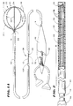
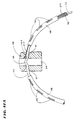
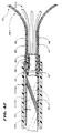
- Fig. 1A shows a multiple electrode probe 10 that embodies the features of the invention.
- the probe 10 includes a flexible catheter tube 12 with a proximal end 14 and a distal end 16.
- the proximal end 14 carries an attached handle 18.
- the distal end 16 carries an electrode support assembly 20.
- the electrode support assembly 20 comprises an array of flexible spline elements 22 assembled to form a three dimensional structure.
- the far ends of the spline elements 22 radiate from a distal hub.
- the near ends of the spline elements 22 are affixed to a base, which the distal end 16 of the catheter tube 12 carries.
- the spline elements 22 comprise thin, rectilinear strips of resilient metal or plastic material. Still, other cross sectional configurations can be used.
- the support assembly 20 retains the spline elements 22 in a three dimensional basket structure.
- the resulting structure can assume other shapes.
- the probe 10 also includes an electrode circuit assembly 28, one for each spline 22.
- Each circuit assembly 28 includes a distal region 30 that contains one or more electrodes 38.
- Each circuit assembly 28 includes a proximal region 32 and an intermediate region 34.
- the electrode-containing distal region 30 is carried by the associated spline 22.
- the proximal region 30 is electrically coupled within the handle 18 to one or more connectors 36 carried outside the handle 18.
- the intermediate region 34 is wrapped about the catheter tube 12.
- the support assembly 20 When deployed for use (as Fig. 1A shows) --for example, inside a heart chamber -- the support assembly 20 holds the electrodes 38 of the distal regions 30 in intimate contact against body tissue.
- the probe 10 includes an outer sheath 40 carried about the catheter tube 12.
- the sheath 40 has an inner diameter that is greater than the outer diameter of the catheter tube 12. As a result, the sheath 40 slides along the catheter tube 12.
- Fig. 2 shows forward movement advances the slidable sheath 40 over the support assembly 20.
- the slidable sheath 40 compresses and collapses the support assembly 20 for introduction through a vein or artery to the intended treatment site within the body.
- FIG. 1A shows, rearward movement retracts the slidable sheath 40 away from the support assembly 20. This removes the compression force.
- the freed support assembly 20 opens and assumes its three dimensional shape.
- the electrode support assembly 20 can be assembled in different ways.
- the drawings exemplify three embodiments.
- Figs. 3 to 13 show a preferred embodiment of a support assembly, identified by reference numeral 20(1).
- two spline elements 22 are paired together in an integral body 42. Two or more spline bodies 22 are joined together to form the assembly 20(1).
- Each body 42 includes a mid-section 44 from which the spline elements 22 extend as an opposed pair of legs.
- the body 42 is generally shaped like a hoop (see Fig. 3).
- the mid-section 44 includes a preformed notch or detent, whose function will be described later.
- the hoop-like body 42 is preferably made from resilient, inert wire, like Nickel Titanium (commercially available as Nitinol material). However, resilient injection molded inert plastic or stainless steel can also be used.
- the distal hub 24 comprises an end cap 48 (see Fig. 10).
- the end cap 48 has a generally cylindrical side wall 50 and a rounded end wall 52.
- a longitudinal bore 54 extends through center the cap 48.
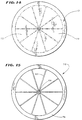
- Slots 56A; 56B; 56C; and 56D extend through the cap 48 diametrically across the center bore 54.
- the number of slots can vary. In the illustrated embodiment, there are four through-slots 56A-D.
- the slots 56A-D are circumferentially spaced about the axis 58 of the bore 54.
- the axis 60 of each slot 56A-D extends diametrically through the center axis 58 (see Figs. 6 and 7), passing through the center bore 54.
- the slot axes 60 are also spaced longitudinally along the bore axis 54.
- the resulting staggered pattern of slots 56A-D is both circumferentially and longitudinally spaced along each 180° segment of the hub 48 (see Figs. 9 and 10). As Fig. 10 best shows, slot 56A is closest to the end wall 52. The slot 56D is farthest from the end wall 52. Intermediately slots 56B and 56C are sequentially spaced in between the slots 56A and 56D.
- the cap 48 is made of an inert, machined metal, like stainless steel.
- the bore 54 and slots 56A-D are preferably formed by conventional EDM techniques. Still, inert molded plastic materials can be used to form the cap 48 and associated openings.
- a spline leg 22 of the hoop-like body 42 can be inserted through a slot 56A-D until the mid-body section 44 enters the bore 54.
- the detent 46 snaps into the bore 54 to lock the body 42 to the end cap 48, with, the opposed pair of spline legs 22 on the body 42 radiating free of the respective slot 56A-D.
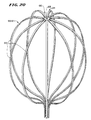
- Sequentially inserting the four hoop-like bodies 42 in the four slots 56A-D orients and locks the spline elements 22 in the radiating pattern shown in Fig. 10.
- the three dimension support assembly 20(1) shown in Fig. 10 results.
- the base 26 includes an anchor member 62 and a mating lock ring 64 (see Figs. 10 to 13).
- the anchor member 62 fits with an interference friction fit into the distal end 16 of the catheter tube 12.
- the lock ring 64 includes a series of circumferentially spaced grooves 66 into which the free ends of the spline legs 22 fit.
- the lock ring 64 fits about the anchor member 62 to capture with an interference fit the free ends of the spline legs 22 between the interior surface of the grooves 66 and the outer surface of the anchor member 62 (see Fig. 13).
- the anchor member 62/lock ring 64 assembly holds the spline elements 22 in a desired flexed condition.
- the hoop-like body 42, slotted end cap 48, and anchor member 62/lock ring 64 assembly minimize the number of the components parts required to form the support assembly 20(1).
- the slotted cap 48 circumferentially aligns and stabilizes the spline elements 22, both circumferentially and longitudinally.
- the sequential insert-and-lock process of the attaching the bodies 42 to the slotted cap 48 also significantly simplifies the assembly process.
- the spline elements 22 extend through the axis of the cap 48 at an angle ⁇ (see Fig. 9B) that is greater than about 45° (as shown by phantom line spline elements 22a in Fig. 9B), but is less than about 110° (as shown by phantom line spline elements 22c in Fig. 9B).
- the angle ⁇ is between about 80° and 100°.
- the angle ⁇ is about 90° (i.e., the spline elements 22c extend generally perpendicular to the axis of the cap 48).
- the angle ⁇ that the cap 48 imposes creates an oval support structure 20(1) having a curvature that best approximates the contour of endocardial heart tissue.
- the oval structure 20(1) includes an enlarged, dome-shaped distal surface area 66 (see Figs. 1 and 10).
- the surface area 66 conforms intimately to endocardial tissue as the heart beats.
- the slotted cap 48 supports the distal ends of the spline elements 22 without imposing reverse or compound bends that force the spline elements 22 inward, out of the natural contour of heart tissue.
- the slotted structure of the cap 48 makes possible the location of the distal-most spline elements 22 very close to the distal end of the cap 48.
- the most distal slot 56A, through which the distal-most spline elements 22 extend has a centerline that is separated from the distal end of the cap 48 by no more than about 1.016mm (0.040").
- the cap 48 projects only a minimal distance beyond the envelope of the resulting structure 20(1). Practically speaking, the cap 48 lies essentially within the envelope of the distal surface area 66.
- the contour of the surface 66 extends along an essentially constant arc from one spline 22, across the end cap 48 to an opposite spline 22.
- the end cap 48 presents a surface 66 free of outward physiologically significant projections that can poke endocardial tissue to cause blunt tissue trauma.
- the contoured surface 66 extending about the cap 48 thus minimizes the chances of damage to endocardial tissue during use.
- the contoured surface 66 permits access to and intimate contact with tissue in the apex of the heart, at the base of the ventricles. About 20% of infarcted heart tissue is found to lie within the apex. Therefore, providing non-traumatic access to this region offers considerable therapeutic benefit.
- the alignment of the end cap 48 along this contoured surface 66 makes it possible to use the end-cap 48 itself as an electrode.
- the contour surface 66 and non-projecting end-cap 48 allow the physician to deploy the structure 20(1) and obtain electrogram signals from the apex of the heart using the end-cap as an electrode. Again, considerable therapeutic benefits result.
- the lower surface 61 of the end cap slots 56 is curved (see Figs. 7 and 8).
- the curved lower surface 61 contacts the spline elements 22 (see Fig. 8) when then are bent, or deflected, a prescribed amount.
- the curvature of the lower slot surface is selected to lend positive support to the spline elements 22 when bent this amount, as Fig. 8 shows.
- the positive support of the surface 61 prevents spline deflection beyond a minimum bend radius.
- the bend radius is selected to be above that which failure-mode stresses are most likely to develop in the spline elements 22.
- failure mode stresses are most likely to occur when the slidable sheath 40 compresses and collapses the spline elements 22.
- the preservation of a minimum bend radius that the cap 48 furnishes prevents sharp bends and failure-mode stresses to develop when the spline elements 22 are collapsed into their most stressed position.
- the specific minimum bend radius selected depends upon the material from which the spline elements 22 are made and the thickness of the spline elements 22. In the preferred embodiment, which uses Nitinol spline elements 22 with a thickness of about 0.177 mm (0.007") the minimum bend radius imposed by the surface 61(shown as radius R in Fig. 7) is about 0.635 mm (0.025")
- the physical characteristics of the support structure 20(1) can be modified by altering the width and/or thickness of the associated spline elements 22.
- the width of the spline elements 22 effects the number of spline elements 22 that the structure 20(1) can accommodate, particularly when collapsed. By reducing the width of individual spline elements 22, the collapsible structure 20(1) can accommodate more spline elements 22. Since the circumferential spacing of the spline elements 22 is least near the cap 48, the spline elements 22 can be locally thinned in this region, when desired, to present a compact geometry that accommodates the collapsing of multiple, closely spaced spline elements 22.
- the thickness of the spline elements 22 effects flexibility and the magnitude of the stress developed during flexing. Thinning the spline element 22 imparts greater flexibility, while at the same time reducing the magnitude of the stress developed during flexing. Since greatest stress upon flexing occurs near the cap 48 (where the greatest degree of bending occurs), the spline elements 22 can be locally thinned in this region, when desired, to impart greater resistance to stress failure.
- the localized reductions of width and/or thickness also reduces force required to collapse the structure 20(1).
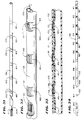
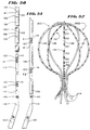
- Figs. 20 shows an alternative embodiment of a support assembly, designated by reference numeral 20(2).
- the support assembly 20(2) includes spline elements 22 radiating in a circumferentially spaced relationship from a center web 68, which constitutes the hub 24. As Figs. 14 to 19 show, the spline elements 22 and web 68 are machined from a single sheet 70 of material.
- the sheet 70 comprises Nickle Titanium stock having a thickness of about 0.102 mm (0.004 inch)
- Other materials like extruded or molded plastic, or stainless steel can be used for the sheet.
- Figs. 14 and 15 show, circumferentially spaced, pie shaped segments 72 are initially cut from the sheet 70, leaving behind the spline elements 22 having the desired width and circumferential spacing.
- One end of the spline elements 22 are connected to the web 68, from which they radiate like spokes.
- the other end of the spline elements 22 are connected to a remaining rim 64 of material.
- Laser cutting or another accurate, mechanized cutting technique like EDM, can be used for this purpose.
- each spline 22 is cut to include a tapered region 76 of reduced width near the web 68.
- This region 76 permits the inclusion of more spline elements 22.
- the region 76 can also present a reduced thickness to impart greater flexibility to the spline elements 22 near the web 68, without otherwise detracting from the mechanical strength of the rest of the spline elements 22. Localized reductions of width and/or thickness also reduces force required to collapse the structure 20(2).
- the spline elements 22 are bent relative to the web 68 to form the desired three dimensional shape of the assembly 20(2).
- the free ends of the spline elements 22 can be joined to an anchor member 62/locking ring 64 assembly, as before described.
- the spline elements 22 extend from the web 68 generally perpendicular to the axis of the web.
- the support structure 20(2) like the structure 20(1), assumes an oval curvature that approximates the contour of endocardial heart tissue.
- the oval structure 20(2) includes an enlarged, dome-shaped distal surface area 66 (see Fig. 20), which conforms intimately to endocardial tissue as the heart beats.
- the spline elements 22, being an integral part of the web 68, include no reverse or compound bends at their junction with the web 68.
- the web 68 lies within the envelope of the distal surface area 66.
- the contour of the surface 66 extends along an essentially constant arc from one spline element 22, across the web 68 to an opposite spline element 22.
- the surface 66 is free of outward, physiologically significant projections that can poke endocardial tissue to cause blunt tissue trauma.
- the contoured surface 66 of the integrated structure 20(2) thus minimizes the chances of damage to endocardial tissue during use.
- the contoured surface 66 also permits access to and intimate contact with tissue in the apex of the heart, at the base of the ventricles.
- the integrated assembly 20(2) also provides a precise geometry that can be accurately machined. It simplifies the manufacture of a support assemblies 20 having multiple spline elements 22.
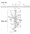
- Figs. 21 to 24 show yet another alternative embodiment of a support assembly, identified by reference numeral 20(3).
- two spline elements 22 are paired together in an integral leaf 78 (see Fig. 21). Two or more leaves 78 are joined together to form the assembly 20(3)(see Figs. 22 and 24).
- Each leaf 78 includes a center web 80 that joins the spline elements 22 together in a diametrically opposed pair.
- the web 80 includes a drilled hole 84 located along the centerline and equidistance from the ends of each leaf 78.
- the leaves 78 are assembled in a stacked relationship about a center pin 86 that extends through the web holes 84.
- the pin 86 holds five leaves 78.
- the leaves 78 are aligned at the pin 86 in an equal circumferentially spaced array comprising ten spline elements.
- the leaves 78 are swaged together in this array between two washers 88.
- the over-molded hub 90 fixes and preserves the desired angular array of the leaves 78.
- the spline elements 22 can be resiliently flexed into the desired three dimensional shapes.
- the web 80 preferably presents a region 82 of reduced width near the hub 90. This region 82 permits the inclusion of more spline elements 22. If desired, the region 82 can also present a reduced thickness to impart greater flexibility to the spline elements 22 near the hub 90, without otherwise detracting from the mechanical strength of the rest of the spline elements 22. Localized reductions of width and/or thickness also reduces force required to collapse the structure 20(3).
- the free ends of the spline elements 22 of the structure 20(3) can be joined to an anchor member 62/locking ring 64 assembly, as before described.
- the spline elements 22 extend generally perpendicularly from the swaged pin 86 and washers 88, which represent the axis of the hub 90.
- the hub 90 thus creates an oval support structure 20(3) like structures 20(1) and 20(2), approximating the contour of endocardial heart tissue.
- the structure 20(3) includes an enlarged, dome-shaped distal surface area 66 (see Figs. 22 and 24), which conforms intimately to endocardial tissue as the heart beats.
- the over-molded hub 90 supports the distal ends of the spline elements 22 without imposing reverse or compound bends that force the spline elements 22 inward, out of the natural contour of heart tissue.
- the over-molded structure of the hub 90 makes possible the location of the distal-most spline elements 22 very close to the distal end of the cap 48, e.g. less than about 1.016 (0.040") between them. As a result (see Fig. 24), when the structure 20(3) is fully deployed for use, the hub 90 projects only a minimal distance beyond the envelope of the resulting structure 20(3).
- the geometry that the over-molded hub 90 creates presents a relatively smooth surface area 66 that is essentially free of major projections that can extend to a significant extent into endocardial tissue.
- the contour of the surface 66 extends along an essentially constant arc from one spline element 22, across the hub 90 to an opposite spline element 22.
- the hub 90 like the end cap 48, presents a surface 66 free of outward physiologically significant projections that can poke endocardial tissue to cause blunt tissue trauma.
- the contoured surface 66 extending about the hub 90 thus minimizes the chances of damage to endocardial tissue during use.
- the contoured surface 66 also permits access to and intimate contact with tissue in the apex of the heart, at the base of the ventricles.
- the over-molded hub 90 also lends positive support to the spline elements 22 when bent into a collapsed position to prevent spline deflection beyond a minimum bend radius.
- the bend radius is selected to be above that which failure-mode stresses are most likely to develop in the spline elements 22.
- the over-molded hub 90 allows the use of spline elements 22 having a greater width to maximize the surface area of the resulting basket structure.
- the support assemblies 20(1); 20(2); and 20(3) are suitable for carrying electrode circuit assemblies 28, which can be assembled in various ways.
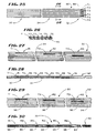
- Figs. 25 to 37 show a preferred embodiment for an electrode circuit assembly, which is identified by reference numeral 28(1) in Fig. 38.
- the assembly 28(1) includes one or more continuous lengths miniature, multi-conductor ribbon cable 92 (see Figs. 25 and 26).
- the ribbon cable 92 includes parallel tracks of electrical conductive wire, designated T1 to T6 in Figs. 25 and 26.
- the conductive wires T1 to T6 are overlaid with an electrical insulating material 94 (see Fig. 26), so that the tracks T1 to T6 are normally insulated one from the other.
- Miniature, multi-conductor ribbon cable 92 can be commercially purchased from Temp-Flex Cable, South Grafton, Massachusetts.
- the cable shown in the preferred embodiment comprises six tracks of 46 AWG bare copper wire (CT37 Alloy), overlaid by electrical insulation PFE material. With insulation, each track measures about 0.0940 mm (0.0037 inch) in outside diameter, with a center-to-center distance of about 0.0991 mm (0.0039 inch).
- the overall width of the 6 track cable is about 0.635 mm (0.025 inch).
- the cable has a D.C. resistance of about 6 ohms per foot; a voltage rating of about 100 volts; and a temperature rating of between about -65°C to about 150°C.
- the electrical circuit 28(1) uses two ribbon cables 92, each having six conductive tracks T1 to T6. Of course, more or fewer tracks can be used, depending upon the overall size limitations imposed.
- the ribbon cables 92 themselves make up the distal region 30, the proximal region 32, and the intermediate region 34 of the circuit assembly 28(1).
- each cable 92 used in the assembly 28(1) is first exposed to focused laser energy or similar technique to selectively remove a section of insulating material along small regions of the tracks T1 to T6, which are designated R1 to R6 in Figs. 27 and 28.
- the exposed regions R1 to R6 are spaced axially from each other from one adjacent track to another.
- each region R1 to R6 measures about 0.889 mm (0.035 inch) in axial length.
- the axial spacing between each region measures about 4.496 mm (0.177 inch).
- the removal of insulating material from each region exposes a portion of the underlying electrical conducting wire T1 to T6.
- a band 96 of electrical conducting material is deposited across the width of the ribbon cable 92 over each exposed region R1 to R6.
- the band 96 is applied by sputtering, vapor deposition, or other appropriate technique.
- each electrode band 96 comprises an undercoat deposition of titanium, followed by an overcoat deposition of platinum.
- the titanium undercoat provides better adherence to the platinum overcoat.
- an alloy of platinum and iridium (90% Pt/10% Ir) is deposited to form each electrode band 96.
- each electrode band that is about 1.143 mm (0.045 inch) in width and about 0.127 ⁇ m to 5.080 ⁇ m (5 to 200 microinches) thick. Thinner depositions provide less stress generation, but thinner depositions lead to greater ohmic resistance. Selecting the thickness requires a balancing of stress generation and ohmic resistance. In the preferred embodiment, each electrode band 96 has a thickness of about 2.540 ⁇ m (100 microinches).
- the act of depositing the band 96 electrically couples the electrical conducting wire T1 to T6 exposed in each region R1 to R6 to the band 96.
- the deposited bands 96 form spaced electrodes, one electrode electrically coupled to each conductive track T1 to T6 of the cable 92.
- Electrodes bands 96 upon the ribbon cable 92 provides an extremely reliable assembly process. Ribbon cables 92 with deposited electrode bands 96 can be prefabricated using efficient mass production techniques, requiring minimal hand labor. The electrical connections are not individually made by hand, thereby avoiding variabilities caused by human error and inattention. Significant improvements in both production economies and quality result.
- the electrode bands 96 are deposited directly on the ribbon cable 92, the resulting electrical connection sites are robust. There are no discontinuities in mechanical properties, like those encountered using conventional soldering, spot welding, or other mechanical joining techniques.
- the deposited electrode bands 96 are extremely thin at the electrical connection site (i.e., they are measured in microinches), they do not generate appreciable stress upon flexing.
- the electrode bands 96 and associated electrical connections bend virtually without generating stress during handling, manipulation, and use.
- the direct deposition of the electrode bands 96 on the ribbon cable 92 provides highly dense, extremely reliable electrical connections that eliminate the need for multiplexing and other expensive techniques at the distal end of the catheter tube, aimed at reducing the number of mechanical electrical connections.
- the direct deposition of electrode bands 96 upon the ribbon cable 92 provides an electrode assembly 28(1) free of any mechanical connections between electrodes and electrical conduction wire.
- the circuit assembly 28(1) includes an electrical insulating sleeve 98.
- the sleeve 98 encloses the distal regions 30 of the two ribbon cables 92, except for their applied electrode bands 96.
- the electrode bands 96 (of which there are a total of twelve in Fig. 38) project through windows 100 in the sleeve 98.
- the distal ends 30 of two ribbon cables 92 are placed within the sleeve 98 by lacing the ribbon cables 92 through the sleeve windows 100. This marries the cables 92 to the sleeve 92, while exposing the electrode bands 92.
- the distal ends of the two ribbon cables laced through the sleeve 98 are designated C1 and C2 in Figs. 31 to 37.
- the sleeve windows 100 are also consecutively numbered W1 to W12 from the most distal end of the sleeve 98 to its most proximal end.
- the sleeve 98 is held by a mandrel (not shown) and cut by blades (also not shown) to form a series of spaced apart slits 102 in the peripheral surface of the sleeve 98.
- the slits 102 extend across the axis of the sleeve 98 for about 40% to 50% of the peripheral surface of the sleeve 98 in a pattern of closely spaced pairs.
- the windows 100 also numbered W1 to W12
- the sleeve material within each window 100 (W1 to W12) is not removed.
- each window 100 (W1 to W12) corresponds with the length of each electrode band 92.
- the spacing between the windows 100 corresponds with the distance between each electrode band 92.
- a guide wire 104 is fastened to the end of the first ribbon cable C1.
- the guide wire is passed into the bore of the sleeve 98. Beginning with the pair of slits 102 that frame the sixth window W6, the wire 104 is threaded up and through the slits 102, passing over the sleeve material between the slits 102.
- the ribbon cable C1 follows (as Fig. 32 shows).
- This progression laces the distal end 30 of the first ribbon cable C1 through the six most distal windows W1 to W6 of the sleeve 98 (as Fig. 34 shows).
- the six electrode bands 92 of the first ribbon cable C1 project through these six most distal windows W1 to W6 (see Figs. 33 and 34).
- the remainder of the first ribbon cable C1 passes through the bore of the sleeve 98 and out its proximal end (as Fig. 34 shows).
- a guide wire 106 is fastened to the end of the second ribbon cable C2.
- the guide wire 106 is passed into the bore of the sleeve 98 over the first ribbon cable C1. Beginning with the pair of slits 102 that frame the most proximal window W12, the wire 106 is threaded up and through the slits 102 in succession, passing over the sleeve material between the slits 102.
- the ribbon cable C2 follows (as Fig. 35 shows) as the wire 106 is threaded up and through slits 102 of windows W12 to W7 (as Figs. 35 to 37 show).
- This progression laces the distal end 30 of the second ribbon cable C2 through the six most proximal windows W12 to W7 of the sleeve 98 (as Fig. 37 shows).
- the six electrode bands 92 of the second ribbon cable C2 project through these six most proximal windows W12 to W7.
- the remainder of the second ribbon cable C2 passes through the bore of the sleeve and out its proximal end (as Fig. 37 shows).
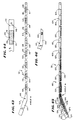
- Fig. 38 shows, the interlaced distal region 30 of sleeve 98 and ribbon cables C1 and C2 slides onto the spline elements 22 of the associated support assembly 20(1).
- the progression of sliding the interlaced distal region 30 onto the spline elements 22 is shown as Step 1; Step 2; and Step 3 in Fig. 38. This progression is also shown in side section in Figs. 39, 40, and 41, respectively.
- Steps 1, 2, and 3 occur before the free ends of the spline elements 22 are fastened to the anchor member 62/lock ring 64 assembly.
- the electrode bands 96 are aligned to face outward on the spline elements (as Fig. 38 shows). These steps are repeated, until all spline elements contains the interlaced distal region 30.
- the sleeve 98 is made of a material that is heat shrunk in situ about the spline 22 at the end of Step 3, as Fig. 41 shows. As heat is applied, the sleeves 98 shrink about the spline 22, securing the interlaced distal regions 30 individually to the spline elements 22.
- an additional insulated signal wire 212 can be passed through one of the sleeves 98 before heat shrinking and electrically connected to the end cap 48.
- the sleeve 98 captures the signal wire 212, securing it to the spline element 22. This obtains the benefit of using the end cap 48 as an additional electrode, as previously discussed.
- the free end of the spline elements 22 are fastened to the anchor member 62/lock ring 64 assembly, in the manner previously described.
- the anchor member 62 is then secured to the distal end 16 of the catheter tube 12 (as Fig. 42 shows).
- the intermediate region 34 of the circuit assembly 28(1) comprises the ribbon cables 92 (i.e., C1 and C2) that extend out of each interlaced sleeve 98 (the signal wire 212 leading to the end cap 48 accompanies the ribbon cables 92 associated with the particular spline element 22 along which the wire 212 runs).
- the ribbon cables 92 are helically wrapped in pairs about the exterior of the catheter tube 12 from its distal end 16 to its proximal end 14.
- the helical wrapping of the eight pairs of ribbon cables 92 about tube 12 maintains the flexibility of the catheter tube 12.
- the helical wrapping also minimizes stress on the ribbon cables 92 when the catheter tube 12 is flexed during use.
- the helical wrapping of the ribbon cables 92 further presents a low profile, allowing use of a catheter tube 12 having a relatively small diameter.
- a catheter tube 12 of approximately 1.981 mm (0.078 inch) in outside diameter will accommodate eight to ten double wrapped pairs of ribbon cables 92 of the type described.
- the helical wrapping of the ribbon cables 92 also leaves the interior bore of the catheter tube 12 open.
- the open interior bore can be used to conduct liquids, or to accommodate another probe for ablation purposes and the like.
- an outer sleeve 108 of heat shrink material is slid into place over the wrapped ribbon cable 92 and tube 12 assembly.
- the sleeve 108 captures the wrapped ribbon cables 92 about the catheter tube 12.
- the proximal region 32 of the circuit assembly 28(1) comprises the ribbon cables 92 that extend from the tube 12 into the handle 18 (as Fig. 1A shows). There, the proximal region 32 connects to two commercially available, external high density connectors 36a and 36b.
- Fig. 1A shows, half of the ribbon cables 92 are coupled the connector 36a, while the other half of the ribbon cables 92 are coupled to the connector 36b.
- the connectors 36a and 36b are over-molded about pin assemblies to which the ribbon cables 92 are electrically connected.
- the connectors 36a and 36b plug into a suitable signal processor (not shown)
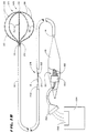
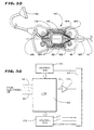
- Fig. 1B shows an alternative embodiment.
- the proximal region 32 connects to a multiplexer 150 carried within the handle 18. All the ribbon cables 32 are electrically coupled to the input of the multiplexer 150.
- the multiplexer 150 is attached to a single low density connector 152.
- the multiplexer 150 reduces the number of connection pins the connector 152 carries, so that the connector 152 can be significantly less expensive than the high density connectors 36a and 36b shown in Fig. 1A.
- the connector 152 plugs into a signal processor 154 which includes a demultiplexer (DMUX) 156 receiving the signals from the multiplexer 150 the probe handle carries.
- DMUX demultiplexer
- the multiplexed signals can be directly digitized by the signal processor 154 without using a DMUX.
- the handle-mounted multiplexer 150 shown in Fig. 1B transfers mostly digital signals. It can therefore can be implemented with relatively straightforward circuitry. It serves as a practical and cost-effective solution to reduce the number of electrical connections in the proximal end of the probe and thereby improve the quality of data acquisition.
- Figs. 55 to 59 show further details of a preferred implementation of mounting the multiplexer 150 in the probe handle 18.
- the handle 18 carries a printed circuit board (PCB) 160. Screw bosses fix the position of the PCB 160 within the handle 18.
- the multiplexer 150 comprises a chip 162 surface mounted on the PCB 160.
- the leads of the chip 162 are connected to the ribbon cables 92 through contact pad arrays 164 (three cables 92 are shown for the purpose of illustration).
- a strain relief 163 surrounds the junction of the proximal catheter tube 14 with the handle 18.
- Decoupling capacitors 166 are preferable present to prevent malfunction of the chip 162 caused by variations in the supply voltage.
- Signal lines 168 connected to the output 176 of the chip 162 lead to the low density connector 152.
- Fig. 56 is a block diagram of the multiplexer chip 162 itself.
- the chip 162 includes an address bus 170 and a control bus 172.
- the address bus 170 has about log2N(e) bits, where N(e) is the number of electrodes 38 carried by the support assembly 20.
- the address bus 170 and control bus 172 are electrically coupled to the data acquisition components of the signal processor 154.
- the buses 170 and 172 control data flow through the chip 162 as the processor 154 works to analyze the signals coming from the electrodes 38.
- the control bus 172 also carries the voltage supply lines V+ and V- and the clock signal from the signal processor 154.
- the chip output 176 preferably includes an amplifier 174.
- the amplifier 174 provides pre-amplification of signals sent to the processor 154 to improve the signal-to-noise ratio.
- the amplifier 174 can be placed on the same die as the chip 162. Alternatively, the amplifier 174 can be placed on a different die, or it can be a separate component mounted in the probe handle 18.
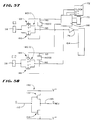
- Fig. 57 shows further details of the multiplexing circuitry 178 of the chip 162, implemented by complimentary metal oxide semiconductor (CMOS) technology.
- the circuitry 178 includes transmission gates 180, one gate being associated with an electrode 38 carried by the support structure 20 (1).
- CMOS complimentary metal oxide semiconductor
- the gates 180(1) and 180(2) each are formed by pairs of P-channel MOSFETS 182 and 184 and N-channel MOSFETS 186 and 188.
- the MOSFETS are metal oxide semiconductor field effect transistors.
- each gate 180(1) and 180(2) is driven by an inverter 190(1) and 190(2).
- each inverter 190 comprises a P-channel transistor 192 and an N-channel transistor 194 connected in parallel between an input lead 193 and an output lead 195.
- the transistors 192 and 194 take a given signal (S in Fig. 58) in the input lead 193 and invert it as output (S REV ) in the output lead 195. In other words, if S is 1, S REV is 0, and vice versa.
- Fig. 57 also shows the input and output leads 193 and 195 of the inverters 190(1) and 190(2). It should be appreciated that the signals handled by the inverter 190(1) differ from the signals handled by the inverted 190(2), as the respective gates 180(1) and 180(2) serve different electrodes E1 and E2.
- the inverters 190 are themselves driven by the outputs of an address decoder 196.
- the decoder 192 comprises a programmable logic array (PLA).
- PPA programmable logic array
- the decoder 196 receives input from the voltage supplies and a clock (through the control bus 172) and other input from the address bus 170.
- each gate 180(1) and 180(2) is conveyed through the amplifier 174 to the signal processor 154.
- Fig. 59 shows a CMOS implementation of the amplifier 174.
- N-channel transistors 198 and 200 form a differential input amplifier biased by the current source 202 of the signal processor 154.
- P-channel transistors 204 and 206 form a current mirror, which acts as an active load for the transistors 198 and 200, thereby increasing the voltage gain.
- the P-channel transistor 208 and the N-channel transistor 210 form the output stage of the amplifier 174, which is electrically coupled to the signal processor 154.
- the multiplexer 150 By mounting the multiplexer 150 in the probe handle 18, the number of electrical connections is considerably reduced. Assuming there are 2 N signals coming from the electrodes 34 on the support structure 20, the multiplexer 150 transports N signals from the address bus 170, and 4 additional signals; i.e., the V+; V-; and clock signal from the control bus 172) and the output to the amplifier 174. The multiplexer 150 therefore only requires a total of N+4 pins in the connectors 152.
- the handle 18 accommodates in a technically efficient way the mounting the circuitry of the multiplexer 150. It avoids the considerable technical challenges involved in reliably fitting all this circuitry in the very compact regions at the distal end 16 of the tube 12.
- Figs. 43 to 54 show a preferred embodiment for an electrode circuit assembly, which is identified by reference numeral 28(2) in Fig. 52.
- the distal portion 30 of the electrode circuit assembly 28(2) includes a flexible substrate 110 (see Fig. 43).
- the substrate is a thin sheet of flexible, electrically non-conducting material. KAPTONTM plastic and like materials can serve this purpose.
- the substrate 110 includes a main body 112 and a tail body 114 that extends at predetermined angle from the main body 112. As will be described in greater detail later, the dog-leg shape of the substrate 110 facilitates the mounting and alignment of the electrode circuit assembly 28(2)on the probe 10.
- the main substrate body 112 measures about 7.6 cm (3 inches)in length and about 0.685 mm (0.027 inch) in width.
- the tail substrate body 114 measures about 1.5 cm (0.6 inch)in length and about 1.22 cm (0.48 inch) in width.
- the angle between the main body 112 and the tail body 114 is about 160°.
- the substrate 110 carries an array of spaced apart electrodes pads 116 on the front surface 118 of the main body 112.
- the electrode pads 116 are preferably deposited upon the front surface 118 by sputtering, vapor deposition, or other appropriate technique.
- the illustrated embodiment shows eight, equally spaced electrode pads 116, which are also identified as E1 to E8 in Fig. 43. These pads 116 are spaced apart for uni-polar operation. Of course, more or fewer pads 116 could be applied, and the pads 116 could be grouped into closer spaced pairs for bi-polar operation.
- each uni-polar electrode pad 116 measures about 1.981 mm (0.078 inch) The pads are separated by about 4.165 mm (0.164 inch).
- Each pad 116 includes a plated through hole or via 120.
- the via 120 extends through the main substrate body 112 between its front surface 118 and back surface 122 (see Figs. 43 and 45). In the illustrated embodiment, each via 120 measures about 0.102 mm (0.004 inch) in diameter.
- the vias 120 are oriented generally along the centerline of each pad 116, but at progressively increasing distances from the longitudinal edge 124 of the substrate 110.
- the via 120 for the most distal pad E1 is located closest to the edge 124, while the via 120 for the most proximal pad E8 is located farthest from the edge 124.
- the intermediate pads E2 to E7 are spaced progressively between these two extremes.
- the substrate 110 also carries an array of connection pads 126 on the back surface 122 of the tail body 114.
- the number of connection pads 126 equals the number of electrode pads 116.
- the connection pads 126 are also designated CP1 to CP8 in Figs. 45 and 47.
- connection pads CP1 to CP8, like the electrode pads E1 to E8, are preferably deposited onto the back substrate surface 122 by sputtering, vapor deposition, or other appropriate technique.
- connection pads CP1 to CP8 are applied in a side-by-side, equally spaced array on the back surface 122 of the tail body 114.
- the connection pads CP1 to CP8 are progressively spaced increasing distances from the longitudinal substrate edge 124.
- the moat proximal connection pad (CP1) lies closest to the edge 124, and the most distal connection pad (CP8) lies farthest away from the edge 124.
- the intermediate pads CP2 to CP7 are spaced progressively between these two extremes.
- connection pads CP1 to CP8 extend at an angle (Angle ⁇ in Fig. 47) from the edge 128.
- the connection pads extend at about a 10° angle from the edge 128 of the tail body 114. The purpose of angling the connection pads will be described in greater detail later.
- each connection pad 126 measures about 0.254 mm (0.010 inch) in width and about 1.270 mm (0.050 inch) in length. The are each spread apart by about 7.6 mm (0.3 inch).
- the substrate 110 further carries traces 130 (see Figs. 45 and 47) that electrically couple one connection pad 126 to one electrode pad 116.
- the traces are also identified as T1 to T8 in Fig. 47.
- the traces T1 to T8 are preferably also deposited by sputtering, vapor deposition, or other appropriate technique upon the back surface 122 of the tail body 114 and main body 112.
- the traces T1 to T8 extend parallel to the edge 124, with the traces spaced side-by-side at progressively greater distances from the edge 124.
- the trace T1 closest to the edge 124 electrically couples the most proximal connection pad (CP1) to the most distal electrode (E1), through the associated via 120.
- the next trace T2 electrically couples the second most proximal connection pad (CP2) to the second most distal electrode (E2), through the associated via 120, and so on.
- each trace 130 is about 0.0432 mm (0.0017 inch) wide.
- the traces 130 are spaced apart by about 0.051 mm (0.002 inch).
- the proximal and intermediate regions 32 and 34 of the electrode circuit assembly 28(2) comprises a continuous length of a miniature, multi-conductor ribbon cable 132 (see Fig. 48), like the cable 92 previously described.
- the ribbon cable 132 includes parallel tracks of electrical conductive wire equal in number to the number of electrode pads 116.
- the cable 132 has eight tracks.
- conductive wires in the tracks are overlaid with an electrical insulating material 134.
- Fig. 49 shows, the most distal end 136 of the cable 132 (which forms a part of the intermediate region 34 of the assembly 28(2)) is electrically coupled to the connection pads 126 carried by the substrate 110.
- the most distal cable end 136 is scarf cut at a steep acute angle (Angle ⁇ in Fig. 48).
- the scarf cut end 136 is stripped of insulating material 134 to expose the individual tracks of conductive wire, identified as T1 to T8 in Figs. 48 and 49.
- Angle ⁇ is generally equal to Angle ⁇ , the angle at which the connection pads extend from the edge 124 of the substrate 110. Therefore, in the illustrated embodiment, Angle ⁇ is about 10°.
- the Angles ⁇ , ⁇ , and ⁇ respectively selected for the scarf cut, the connection pads CP1 to CP8, and the exposed tracks T1 to T8 take into account the physical dimensions of the ribbon cable (i.e., its pitch, width, and thickness), the size constraints physiologically imposed upon the assembly 28(2), and the desired therapeutic performance of the probe 10 dictating the number and arrangement of electrodes.
- the Angles ⁇ , ⁇ , and ⁇ are selected, given these multiple considerations, to align the tracks T1 to T8 of the ribbon cable 132 in a technically workable way for resistance welding to the individual connection pads CP1 to CP8.
- the distance between the wire tracks T1 to T8 on the ribbon cable 132 is about 0.0991 mm (0.0039 inch).
- the eight track ribbon cable 132 measures about 0.813 mm (0.032 inch) in width and about 0.102 mm (0.004 inch)in thickness.
- the staggered pattern of eight connection pads CP1 to CP8 on the substrate 110 measures about 15.2 mm (0.6 inch) in horizontal length and about 1.219 mm (0.048 inch) in vertical width.
- scarf cut Angle ⁇ is about 3.5°. This scarf cut, together with a connection pad and connection wire Angles ⁇ and ⁇ of about 10°, provide a workable alignment, as Fig. 49 shows.
- the substrate 110 is laced, distal end first (see Fig. 50) through a sleeve 138 containing slits 102 forming eight windows 100 (also numbered W1 to W8) that accommodate the eight electrode pads E1 to E8.
- the main body 112 of the substrate 110 is laced through the sleeve 138 beginning with the most proximal window W8 toward the most distal window W1 in the same manner that the ribbon cables C1 or C2 are individually laced within the sleeve 98 (as Figs. 31 to 37 show).
- the eight electrode pads 116 (E1 to E8) on the substrate 110 project through the eight windows 100 (W1 to W8).
- the tail body 114 of the substrate 110 and attached ribbon cable 132 extend outward beyond the proximal end of the sleeve 138 (as Fig. 51 also shows).
- Fig. 52 shows, the interlaced sleeve 138 and substrate 110 slides onto the spline elements 22 of the associated support assembly 20(1).
- the interlaced distal ends 30 are heat shrunk about the spline elements 22, as previously described.
- Fig. 53 shows, the free end of the spline elements 22 (and associated substrate body 112) are fitted into the anchor member 62/lock ring 64 assembly that forms the base 26, in the manner previously described (see Figs. 10 to 13).
- the substrate body 112 preferably includes an alignment mark 140 near its junction with the tail body 114 (see Figs. 46, 50, and 51).
- the alignment mark 140 indicates the location where the anchor member 62/lock ring 64 assembly should engage each substrate 110.
- the mark 140 assures that all substrates 110 and associated spline elements 22 are mutually aligned with each other about the base 26 (see Fig. 53).
- the mark 140 also assures that the same portion of the main substrate body 112 and the entire tail body 114 extends beyond the base 26, for reasons that will be explained later.
- the joined base 26 and the support assembly 20(1) is then secured to the distal end 16 of the catheter tube 12 (as Fig. 53 shows).
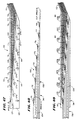
- the intermediate regions 34 of the eight circuit assemblies 28(2) on the support assembly 20(1) (comprising eight ribbon cables 132 attached to the tail bodies 114) are helically wrapped about the exterior of the catheter tube 12 (see Figs. 53 and 54).
- the angled tail body 114 of the substrate 110 directly orients the attached ribbon cable 132 for helical wrapping about the catheter tube 12.
- an Angle ⁇ of 160° presents the ribbon cable 132 for a 20° helical wrap (that is, the angle of the helical wrap and Angle ⁇ of the tail body 114 are supplementary angles).
- a 20° helical wraps overlies the eight ribbon cables 132 in two layers about the tube 12.
- the ribbon cables 132 for odd numbered spline elements (identified as S1, S3, and S5 in Figs. 53 and 54) are wrapped on the bottom layer, and the ribbon cables 132 for even numbered spline elements (identified as S2 and S4 are wrapped on the top layer), or vice versa.
- the outer sleeve 108 of heat shrink material is slid into place over the tube 12 and wrapped ribbon cables 132, in the manner previously described (see Fig. 42).
- the catheter tube 12 presents a diameter of about 8 French. And, as before described, the central lumen of the catheter tube 12 is left completely open to accommodate an ablation catheter or the like.
- the proximal regions 32 of the electrode circuits 28(2) are connected within the probe handle 18 to one or more commercially available, external high density connectors 36a and 36b (as Fig. 1A shows) or to a single low density connector 154 via a multiplexer 152 carried in the probe handle 18 (as Fig. 1B shows).
- the sleeve 98 supports multiple electrodes 38 and adjacent electrical conduction wires associated with the distal region 30 of the electrode circuit assembly 28.
- the sleeve 98 is itself joined about a stiffener member (i.e., a spline element 22).
- Multiple sleeve-bearing stiffener members 22 are themselves mechanically connected to and constrained at opposite ends to create the three dimensional support structure 20 for the electrodes 28.
- the stiffener members 22 orient the electrodes into a predetermined circumferential distribution, while the sleeves retain the electrodes in an exposed, longitudinally separated condition on the stiffener members 22.
- This structure 20 is supported on a catheter tube 12.
- the sleeve 98 terminates shaft of the catheter tube 12, so that the electrical conduction wires of the proximal and intermediate regions 32 and 34 of the electrode circuit assembly 28 are exposed outside the sleeve 98.
- the intermediate region 34 is stabilized along the catheter tube 12 outside the sleeve 98.
- the proximal region 32 is enclosed within a handle 18 for attachment to external connectors.
Claims (13)
- Structure de support d'électrode (20), comprenant:un moyeu (24) ayant un axe (58) et une paroi latérale (50) située autour de l'axe (58),au moins deux éléments en cannelures (22) diamétralement opposés et généralement souples raccordés au moyeu (24), les éléments en cannelures (22) ayant des extrémités espacées du moyeu (24),une base (26) raccordée aux extrémités des éléments en cannelures (22) pour faire fléchir les éléments en cannelures (22) dans une forme tridimensionnelle prédéterminée, etau moins l'un des éléments en cannelures (22) portant une électrode (38),
caractérisée en ce que les éléments en cannelures (22) rayonnent vers l'extérieur à partir de la paroi latérale (50) du moyeu selon un angle (χ), mesuré par rapport à l'axe (58) du moyeu, compris entre 45 et 110°. - Structure de support (20) selon la revendication 1, dans laquelle l'angle de rayonnement (χ) se situe entre environ 80° et environ 100°.
- Structure de support (20) selon la revendication 1, dans laquelle l'angle de rayonnement (χ) est d'environ 90°.
- Structure de support (20) selon la revendication 1,
dans laquelle la forme tridimensionnelle comprend une surface distale incurvée (66) autour du moyeu (24), et
dans laquelle le moyeu (24) se situe de manière générale dans l'enveloppe de la surface distale incurvée (66). - Structure de support (20) selon la revendication 1,
dans laquelle le moyeu (24) comprend une extrémité proximale qui fait face à la base (26) et une extrémité distale qui est opposée à distance à la base (26), et
dans laquelle le raccordement des éléments en cannelures (22) avec le moyeu (24) est plus proche de l'extrémité distale du moyeu (24) que de l'extrémité proximale du moyeu (24). - Structure de support (20) selon la revendication 1,
dans laquelle le moyeu (24) comprend une surface intérieure incurvée (61) qui vient en contact avec les éléments en cannelures (22) lorsqu'ils sont fléchis sur une distance prédéterminée par rapport au moyeu (24) afin d'établir un rayon de courbure minimal pour les éléments en cannelures (22). - Structure de support (20) selon la revendication 1,
dans laquelle les éléments en cannelures (22) sont joints d'une seule pièce par un corps intermédiaire (44) qui est raccordé au moyeu (24). - Structure de support (20) selon la revendication 7,
dans laquelle le moyeu (24) est surmoulé sur le corps intermédiaire (44). - Structure de support (20) selon la revendication 7,
dans laquelle le moyeu (24) comprend une fente (56) qui s'étend en travers de l'axe à travers le moyeu, et
dans laquelle le corps intermédiaire (44) est capturé à l'intérieur de la fente (56) tandis que les éléments en cannelures opposés (22) irradient librement depuis la fente. - Structure de support (20) selon la revendication 1,
dans laquelle les éléments en cannelures (22) et le moyeu (24) sont formés d'une seule pièce à partir d'une seule feuille de matériau. - Structure de support (20) selon la revendication 1,
dans laquelle chaque élément en cannelure (22) comprend une région de largeur réduite à proximité du moyeu (24). - Structure de support (20) selon la revendication 1,
dans laquelle chaque élément en cannelure (22) comprend une région d'épaisseur réduite à proximité du moyeu (24). - Structure de support (20) selon la revendication 1,
dans laquelle le moyeu (24) sert également d'électrode.
Applications Claiming Priority (5)
| Application Number | Priority Date | Filing Date | Title |
|---|---|---|---|
| US3364093A | 1993-03-16 | 1993-03-16 | |
| US33640 | 1993-03-16 | ||
| US20641494A | 1994-03-04 | 1994-03-04 | |
| US206414 | 1994-03-04 | ||
| PCT/US1994/002795 WO1994021166A1 (fr) | 1993-03-16 | 1994-03-15 | Structures de support d'electrodes multiples |
Publications (3)
| Publication Number | Publication Date |
|---|---|
| EP0689397A1 EP0689397A1 (fr) | 1996-01-03 |
| EP0689397A4 EP0689397A4 (fr) | 1998-06-17 |
| EP0689397B1 true EP0689397B1 (fr) | 2000-07-12 |
Family
ID=26709946
Family Applications (1)
| Application Number | Title | Priority Date | Filing Date |
|---|---|---|---|
| EP94911602A Expired - Lifetime EP0689397B1 (fr) | 1993-03-16 | 1994-03-15 | Structures de support d'electrodes multiples |
Country Status (7)
| Country | Link |
|---|---|
| US (1) | US5647870A (fr) |
| EP (1) | EP0689397B1 (fr) |
| JP (1) | JP3423719B2 (fr) |
| AT (1) | ATE194469T1 (fr) |
| CA (1) | CA2158453C (fr) |
| DE (1) | DE69425249T2 (fr) |
| WO (1) | WO1994021166A1 (fr) |
Cited By (1)
| Publication number | Priority date | Publication date | Assignee | Title |
|---|---|---|---|---|
| US9504399B2 (en) | 2011-04-22 | 2016-11-29 | Topera, Inc. | Basket style cardiac mapping catheter having a flexible electrode assembly for sensing monophasic action potentials |
Families Citing this family (168)
| Publication number | Priority date | Publication date | Assignee | Title |
|---|---|---|---|---|
| US5904680A (en) * | 1992-09-25 | 1999-05-18 | Ep Technologies, Inc. | Multiple electrode support structures having optimal bio-mechanical characteristics |
| US5893847A (en) | 1993-03-16 | 1999-04-13 | Ep Technologies, Inc. | Multiple electrode support structures with slotted hub and hoop spline elements |
| US6216043B1 (en) * | 1994-03-04 | 2001-04-10 | Ep Technologies, Inc. | Asymmetric multiple electrode support structures |
| EP0784453B1 (fr) * | 1994-10-07 | 2003-09-24 | Boston Scientific Limited | Structure flexible supportant des electrodes |
| US6152899A (en) | 1996-03-05 | 2000-11-28 | Vnus Medical Technologies, Inc. | Expandable catheter having improved electrode design, and method for applying energy |
| US6036687A (en) * | 1996-03-05 | 2000-03-14 | Vnus Medical Technologies, Inc. | Method and apparatus for treating venous insufficiency |
| US7027869B2 (en) | 1998-01-07 | 2006-04-11 | Asthmatx, Inc. | Method for treating an asthma attack |
| US7425212B1 (en) * | 1998-06-10 | 2008-09-16 | Asthmatx, Inc. | Devices for modification of airways by transfer of energy |
| US6634363B1 (en) * | 1997-04-07 | 2003-10-21 | Broncus Technologies, Inc. | Methods of treating lungs having reversible obstructive pulmonary disease |
| US7992572B2 (en) | 1998-06-10 | 2011-08-09 | Asthmatx, Inc. | Methods of evaluating individuals having reversible obstructive pulmonary disease |
| US6179832B1 (en) * | 1997-09-11 | 2001-01-30 | Vnus Medical Technologies, Inc. | Expandable catheter having two sets of electrodes |
| US7921855B2 (en) | 1998-01-07 | 2011-04-12 | Asthmatx, Inc. | Method for treating an asthma attack |
| CA2329400C (fr) * | 1998-04-23 | 2005-01-04 | Scimed Life Systems, Inc. | Dispositif d'extraction medicale comportant un panier a boucles |
| US8181656B2 (en) | 1998-06-10 | 2012-05-22 | Asthmatx, Inc. | Methods for treating airways |
| US7198635B2 (en) | 2000-10-17 | 2007-04-03 | Asthmatx, Inc. | Modification of airways by application of energy |
| US5945736A (en) * | 1998-09-28 | 1999-08-31 | Chip Coolers, Inc. | Heat sink assembly with snap-in cover plate having multiple pressure capability |
| US8257428B2 (en) | 1999-08-09 | 2012-09-04 | Cardiokinetix, Inc. | System for improving cardiac function |
| US8388672B2 (en) | 1999-08-09 | 2013-03-05 | Cardiokinetix, Inc. | System for improving cardiac function by sealing a partitioning membrane within a ventricle |
| US10307147B2 (en) | 1999-08-09 | 2019-06-04 | Edwards Lifesciences Corporation | System for improving cardiac function by sealing a partitioning membrane within a ventricle |
| US9694121B2 (en) | 1999-08-09 | 2017-07-04 | Cardiokinetix, Inc. | Systems and methods for improving cardiac function |
| US8529430B2 (en) * | 2002-08-01 | 2013-09-10 | Cardiokinetix, Inc. | Therapeutic methods and devices following myocardial infarction |
| US7674222B2 (en) | 1999-08-09 | 2010-03-09 | Cardiokinetix, Inc. | Cardiac device and methods of use thereof |
| US8246671B2 (en) | 1999-08-09 | 2012-08-21 | Cardiokinetix, Inc. | Retrievable cardiac devices |
| US8251070B2 (en) | 2000-03-27 | 2012-08-28 | Asthmatx, Inc. | Methods for treating airways |
| US9332993B2 (en) | 2004-08-05 | 2016-05-10 | Cardiokinetix, Inc. | Devices and methods for delivering an endocardial device |
| US9332992B2 (en) | 2004-08-05 | 2016-05-10 | Cardiokinetix, Inc. | Method for making a laminar ventricular partitioning device |
| US9078660B2 (en) | 2000-08-09 | 2015-07-14 | Cardiokinetix, Inc. | Devices and methods for delivering an endocardial device |
| US7399271B2 (en) * | 2004-01-09 | 2008-07-15 | Cardiokinetix, Inc. | Ventricular partitioning device |
| US10064696B2 (en) | 2000-08-09 | 2018-09-04 | Edwards Lifesciences Corporation | Devices and methods for delivering an endocardial device |
| US7104987B2 (en) | 2000-10-17 | 2006-09-12 | Asthmatx, Inc. | Control system and process for application of energy to airway walls and other mediums |
| US6893431B2 (en) | 2001-10-15 | 2005-05-17 | Scimed Life Systems, Inc. | Medical device for delivering patches |
| US6895267B2 (en) | 2001-10-24 | 2005-05-17 | Scimed Life Systems, Inc. | Systems and methods for guiding and locating functional elements on medical devices positioned in a body |
| WO2003047134A2 (fr) * | 2001-11-28 | 2003-06-05 | Bridgeco Ag | Procede de synchronisation dans des reseaux |
| AUPS226402A0 (en) * | 2002-05-13 | 2002-06-13 | Advanced Metal Coatings Pty Limited | An ablation catheter |
| US20040153056A1 (en) * | 2002-11-11 | 2004-08-05 | Berchtold Holding Gmbh, A German Corporation | Probe |
| JP2004246317A (ja) * | 2002-12-20 | 2004-09-02 | Hitachi Ltd | 冷陰極型フラットパネルディスプレイ |
| US9101383B1 (en) | 2003-04-25 | 2015-08-11 | Annex Medical, Inc. | Medical retrieval device |
| US20040226556A1 (en) | 2003-05-13 | 2004-11-18 | Deem Mark E. | Apparatus for treating asthma using neurotoxin |
| US7366557B2 (en) * | 2003-11-07 | 2008-04-29 | Biosense Webster, Inc. | Flower catheter |
| US20050137646A1 (en) * | 2003-12-22 | 2005-06-23 | Scimed Life Systems, Inc. | Method of intravascularly delivering stimulation leads into brain |
| US8060207B2 (en) * | 2003-12-22 | 2011-11-15 | Boston Scientific Scimed, Inc. | Method of intravascularly delivering stimulation leads into direct contact with tissue |
| US7295875B2 (en) * | 2004-02-20 | 2007-11-13 | Boston Scientific Scimed, Inc. | Method of stimulating/sensing brain with combination of intravascularly and non-vascularly delivered leads |
| US7590454B2 (en) * | 2004-03-12 | 2009-09-15 | Boston Scientific Neuromodulation Corporation | Modular stimulation lead network |
| US20050203600A1 (en) | 2004-03-12 | 2005-09-15 | Scimed Life Systems, Inc. | Collapsible/expandable tubular electrode leads |
| US7177702B2 (en) | 2004-03-12 | 2007-02-13 | Scimed Life Systems, Inc. | Collapsible/expandable electrode leads |
| US7231260B2 (en) | 2004-05-06 | 2007-06-12 | Boston Scientific Scimed, Inc. | Intravascular self-anchoring electrode body with arcuate springs, spring loops, or arms |
| US7286879B2 (en) | 2004-07-16 | 2007-10-23 | Boston Scientific Scimed, Inc. | Method of stimulating fastigium nucleus to treat neurological disorders |
| WO2006052940A2 (fr) | 2004-11-05 | 2006-05-18 | Asthmatx, Inc. | Dispositif medical presentant des caracteristiques permettant d'ameliorer une intervention |
| US7949407B2 (en) | 2004-11-05 | 2011-05-24 | Asthmatx, Inc. | Energy delivery devices and methods |
| CA2585150C (fr) * | 2004-11-12 | 2014-10-07 | Asthmatx, Inc. | Dispositifs et methodes ameliores d'apport d'energie |
| US20070093802A1 (en) | 2005-10-21 | 2007-04-26 | Danek Christopher J | Energy delivery devices and methods |
| US7937160B2 (en) | 2004-12-10 | 2011-05-03 | Boston Scientific Neuromodulation Corporation | Methods for delivering cortical electrode leads into patient's head |
| US8523879B1 (en) | 2005-03-31 | 2013-09-03 | Stuart J. Lind | Stone retriever for flexible endoscopes having small diameter working channels |
| DE102005040214A1 (de) * | 2005-08-15 | 2007-03-01 | Epflex Feinwerktechnik Gmbh | Mehrdrahteinheit und Herstellungsverfahren hierfür |
| US8414574B2 (en) * | 2006-06-01 | 2013-04-09 | Hoya Corporation | Treatment instrument having a front-end treatment member |
| US7729752B2 (en) | 2006-06-13 | 2010-06-01 | Rhythmia Medical, Inc. | Non-contact cardiac mapping, including resolution map |
| US7515954B2 (en) | 2006-06-13 | 2009-04-07 | Rhythmia Medical, Inc. | Non-contact cardiac mapping, including moving catheter and multi-beat integration |
| US7931647B2 (en) | 2006-10-20 | 2011-04-26 | Asthmatx, Inc. | Method of delivering energy to a lung airway using markers |
| US8588885B2 (en) * | 2007-05-09 | 2013-11-19 | St. Jude Medical, Atrial Fibrillation Division, Inc. | Bendable catheter arms having varied flexibility |
| WO2008141150A2 (fr) | 2007-05-09 | 2008-11-20 | Irvine Biomedical, Inc. | Cathéter à panier possédant de multiples électrodes |
| KR100865951B1 (ko) * | 2007-07-11 | 2008-11-03 | 김형일 | 대뇌피질 자극을 위한 자가확장이 가능한 경막외 전극장치 |
| US8235983B2 (en) | 2007-07-12 | 2012-08-07 | Asthmatx, Inc. | Systems and methods for delivering energy to passageways in a patient |
| US8103327B2 (en) * | 2007-12-28 | 2012-01-24 | Rhythmia Medical, Inc. | Cardiac mapping catheter |
| US8483831B1 (en) | 2008-02-15 | 2013-07-09 | Holaira, Inc. | System and method for bronchial dilation |
| CN102014779B (zh) | 2008-05-09 | 2014-10-22 | 赫莱拉公司 | 用于治疗支气管树的系统、组件和方法 |
| JP2011522633A (ja) * | 2008-06-06 | 2011-08-04 | バリックス・メディカル・コーポレイション | 血管治療装置および方法 |
| US8137343B2 (en) | 2008-10-27 | 2012-03-20 | Rhythmia Medical, Inc. | Tracking system using field mapping |
| US20100160906A1 (en) * | 2008-12-23 | 2010-06-24 | Asthmatx, Inc. | Expandable energy delivery devices having flexible conductive elements and associated systems and methods |
| US9339331B2 (en) | 2008-12-29 | 2016-05-17 | St. Jude Medical, Atrial Fibrillation Division, Inc. | Non-contact electrode basket catheters with irrigation |
| US7955299B2 (en) * | 2008-12-29 | 2011-06-07 | St. Jude Medical, Atrial Fibrillation Division, Inc. | Seal for controlling irrigation in basket catheters |
| US20100198209A1 (en) * | 2009-01-30 | 2010-08-05 | Tartaglia Joseph M | Hemorrhoid Therapy and Method |
| WO2010093603A1 (fr) | 2009-02-11 | 2010-08-19 | Boston Scientific Scimed, Inc. | Dispositifs de cathéters d'ablation isolés et procédés d'utilisation |
| US8571647B2 (en) | 2009-05-08 | 2013-10-29 | Rhythmia Medical, Inc. | Impedance based anatomy generation |
| US8103338B2 (en) | 2009-05-08 | 2012-01-24 | Rhythmia Medical, Inc. | Impedance based anatomy generation |
| US9366351B2 (en) * | 2009-06-30 | 2016-06-14 | Robertshaw Controls Company | Water tight valve having sealed flying leads |
| WO2011008444A1 (fr) | 2009-06-30 | 2011-01-20 | Boston Scientific Scimed, Inc. | Cathéter hybride irrigué ouvert de cartographie et d'ablation |
| WO2011056578A2 (fr) | 2009-10-26 | 2011-05-12 | Cardiokinetix, Inc. | Réduction du volume ventriculaire |
| CN112089394A (zh) | 2009-10-27 | 2020-12-18 | 努瓦拉公司 | 具有可冷却的能量发射组件的递送装置 |
| US8911439B2 (en) | 2009-11-11 | 2014-12-16 | Holaira, Inc. | Non-invasive and minimally invasive denervation methods and systems for performing the same |
| WO2011060200A1 (fr) | 2009-11-11 | 2011-05-19 | Innovative Pulmonary Solutions, Inc. | Systèmes, appareils et procédés pour traiter un tissu et contrôler une sténose |
| US9131869B2 (en) | 2010-05-11 | 2015-09-15 | Rhythmia Medical, Inc. | Tracking using field mapping |
| US9089340B2 (en) | 2010-12-30 | 2015-07-28 | Boston Scientific Scimed, Inc. | Ultrasound guided tissue ablation |
| US9241687B2 (en) | 2011-06-01 | 2016-01-26 | Boston Scientific Scimed Inc. | Ablation probe with ultrasonic imaging capabilities |
| US9119636B2 (en) | 2011-06-27 | 2015-09-01 | Boston Scientific Scimed Inc. | Dispersive belt for an ablation system |
| US9414738B2 (en) | 2011-08-25 | 2016-08-16 | Covidien Lp | Expandable support structure and operative element for delivery through a working channel |
| JP6117209B2 (ja) | 2011-09-14 | 2017-04-19 | ボストン サイエンティフィック サイムド,インコーポレイテッドBoston Scientific Scimed,Inc. | 複数のアブレーションモードを備えたアブレーション装置及び同アブレーション装置を含むシステム |
| AU2012308464B2 (en) | 2011-09-14 | 2016-10-20 | Boston Scientific Scimed, Inc. | Ablation device with ionically conductive balloon |
| US9241761B2 (en) | 2011-12-28 | 2016-01-26 | Koninklijke Philips N.V. | Ablation probe with ultrasonic imaging capability |
| US8825130B2 (en) | 2011-12-30 | 2014-09-02 | St. Jude Medical, Atrial Fibrillation Division, Inc. | Electrode support structure assemblies |
| WO2013106557A1 (fr) | 2012-01-10 | 2013-07-18 | Boston Scientific Scimed, Inc. | Système d'électrophysiologie |
| JP5830614B2 (ja) | 2012-01-31 | 2015-12-09 | ボストン サイエンティフィック サイムド,インコーポレイテッドBoston Scientific Scimed,Inc. | 超音波組織撮像のための流体に基づいた音響結合を有するアブレーションプローブ、および、アブレーションおよび超音波撮像システム |
| US20130296729A1 (en) | 2012-05-04 | 2013-11-07 | Biosense Webster (Israel), Ltd. | Catheter having two-piece connector for a split handle assembly |
| EP2854682B1 (fr) | 2012-06-04 | 2021-06-23 | Boston Scientific Scimed, Inc. | Systèmes pour le traitement d'un tissu dans une voie de passage au sein d'un corps |
| CN104394759B (zh) | 2012-06-20 | 2017-04-05 | 波士顿科学医学有限公司 | 多电极egm上使用多维信号空间矢量分析的远场对局部激活区别 |
| WO2014058484A1 (fr) | 2012-06-20 | 2014-04-17 | Boston Scientific Scimed, Inc. | Analyse améliorée de vecteurs de signaux pour supprimer l'activation globale pendant une cartographie électrophysiologique |
| US9526426B1 (en) | 2012-07-18 | 2016-12-27 | Bernard Boon Chye Lim | Apparatus and method for assessing tissue composition |
| US10499984B2 (en) | 2012-07-18 | 2019-12-10 | Bernard Boon Chye Lim | Apparatus and method for assessing tissue treatment |
| US10881459B2 (en) | 2012-07-18 | 2021-01-05 | Bernard Boon Chye Lim | Apparatus and method for assessing tissue treatment |
| WO2014018153A1 (fr) | 2012-07-24 | 2014-01-30 | Boston Scientific Scimed, Inc. | Électrodes pour traitement de tissu |
| US9011369B2 (en) * | 2012-08-23 | 2015-04-21 | Anmol Gupta | High flux basket catheter for efficient continuous flow peritoneal dialysis |
| EP2897544B1 (fr) | 2012-09-18 | 2018-12-12 | Boston Scientific Scimed, Inc. | Cartographie et ablation à l'aide d'un cathéter d'ablation refroidi en boucle fermée |
| US9211156B2 (en) | 2012-09-18 | 2015-12-15 | Boston Scientific Scimed, Inc. | Map and ablate closed-loop cooled ablation catheter with flat tip |
| US9272132B2 (en) | 2012-11-02 | 2016-03-01 | Boston Scientific Scimed, Inc. | Medical device for treating airways and related methods of use |
| WO2014071372A1 (fr) | 2012-11-05 | 2014-05-08 | Boston Scientific Scimed, Inc. | Dispositifs de distribution d'énergie à des lumières corporelles |
| JP2016501640A (ja) | 2012-12-20 | 2016-01-21 | ボストン サイエンティフィック サイムド,インコーポレイテッドBoston Scientific Scimed,Inc. | 時系列パターンマッチングを用いたロータ特定 |
| US9427167B2 (en) | 2012-12-20 | 2016-08-30 | Boston Scientific Scimed, Inc. | Real-time feedback for electrode contact during mapping |
| US9681817B2 (en) | 2012-12-20 | 2017-06-20 | Boston Scientific Scimed, Inc. | Suppression of global activation signals during anatomical mapping |
| JP6144360B2 (ja) | 2012-12-27 | 2017-06-07 | ボストン サイエンティフィック サイムド,インコーポレイテッドBoston Scientific Scimed,Inc. | 電気生理学的マッピング中に遠距離場活動を抑制するためのアーティファクト除去に用いるカテーテルシステム |
| US9398933B2 (en) | 2012-12-27 | 2016-07-26 | Holaira, Inc. | Methods for improving drug efficacy including a combination of drug administration and nerve modulation |
| US9089272B2 (en) | 2013-01-02 | 2015-07-28 | Boston Scientific Scimed Inc. | Estimating restitution curves in an anatomical mapping system |
| EP2943119B1 (fr) | 2013-01-14 | 2021-09-22 | Boston Scientific Scimed, Inc. | Reconstruction d'une information d'activation cardiaque basée sur des moyens électriques et mécaniques |
| US10602947B2 (en) | 2013-04-11 | 2020-03-31 | Biosense Webster (Israel), Ltd. | High density electrode structure |
| US10575743B2 (en) | 2013-04-11 | 2020-03-03 | Biosense Webster (Israel) Ltd. | High electrode density basket catheter |
| US9636032B2 (en) | 2013-05-06 | 2017-05-02 | Boston Scientific Scimed Inc. | Persistent display of nearest beat characteristics during real-time or play-back electrophysiology data visualization |
| US9186080B2 (en) | 2013-05-07 | 2015-11-17 | Boston Scientific Scimed Inc. | System for identifying rotor propagation vectors |
| JP6182665B2 (ja) | 2013-05-14 | 2017-08-16 | ボストン サイエンティフィック サイムド,インコーポレイテッドBoston Scientific Scimed,Inc. | ベクトル場を用いた電気生理学的マッピング中の活動パターンの表示及び特定のためのカテーテルシステム |
| US9144391B2 (en) | 2013-05-16 | 2015-09-29 | Boston Scientific Scimed Inc. | Enhanced activation onset time optimization by similarity based pattern matching |
| US9814618B2 (en) | 2013-06-06 | 2017-11-14 | Boston Scientific Scimed, Inc. | Devices for delivering energy and related methods of use |
| US20150045863A1 (en) * | 2013-08-07 | 2015-02-12 | Boston Scientific Scimed, Inc. | Expandable electrodes and methods for treating tissues |
| CN105451680B (zh) * | 2013-08-09 | 2019-10-08 | 波士顿科学国际有限公司 | 可扩张导管以及制造和使用的相关方法 |
| JP2016530008A (ja) | 2013-08-28 | 2016-09-29 | ボストン サイエンティフィック サイムド,インコーポレイテッドBoston Scientific Scimed,Inc. | 電気生理学的マッピング中のデータセグメントにおける活性化パターンの優勢度を予測すること |
| JP6203951B2 (ja) | 2013-10-31 | 2017-09-27 | ボストン サイエンティフィック サイムド,インコーポレイテッドBoston Scientific Scimed,Inc. | 局所一致を使用する高解像度マッピング用の医療用デバイス |
| WO2015066322A1 (fr) | 2013-11-01 | 2015-05-07 | Boston Scientific Scimed, Inc. | Cartographie cardiaque au moyen de l'interpolation de latence |
| US9597140B2 (en) * | 2014-01-31 | 2017-03-21 | Medtronic Cryocath Lp | Accessory to allow sensing at balloon interface |
| WO2015134276A1 (fr) | 2014-03-07 | 2015-09-11 | Boston Scientific Scimed, Inc. | Dispositifs médicaux pour le mappage de tissu cardiaque |
| JP2017509399A (ja) | 2014-03-11 | 2017-04-06 | ボストン サイエンティフィック サイムド,インコーポレイテッドBoston Scientific Scimed,Inc. | 心臓組織をマッピングするための医療用デバイス |
| US20150265341A1 (en) | 2014-03-18 | 2015-09-24 | Boston Scientific Scimed, Inc. | Electrophysiology system |
| US10952704B2 (en) | 2014-04-11 | 2021-03-23 | Koninklijke Philips N.V. | Needle with thin film piezoelectric sensors |
| JP6336620B2 (ja) * | 2014-05-06 | 2018-06-06 | セント・ジュード・メディカル,カーディオロジー・ディヴィジョン,インコーポレイテッド | 電極支持構造アセンブリ |
| WO2015187371A1 (fr) | 2014-06-03 | 2015-12-10 | Boston Scientific Scimed, Inc. | Dispositifs médicaux pour la cartographie du tissu cardiaque |
| WO2015187386A1 (fr) * | 2014-06-03 | 2015-12-10 | Boston Scientific Scimed, Inc. | Ensemble électrode ayant un embout distal atraumatique |
| WO2015187430A2 (fr) | 2014-06-04 | 2015-12-10 | Boston Scientific Scimed, Inc. | Ensemble électrode |
| US9730603B2 (en) | 2014-06-20 | 2017-08-15 | Boston Scientific Scimed Inc. | Medical devices for mapping cardiac tissue |
| WO2016007901A1 (fr) * | 2014-07-11 | 2016-01-14 | Boston Scientific Scimed, Inc. | Dispositifs médicaux d'ablation |
| RU2017114607A (ru) | 2014-09-28 | 2018-10-29 | Кардиокинетикс, Инк. | Устройства для терапии нарушений функции сердца |
| CN106793968A (zh) | 2014-10-13 | 2017-05-31 | 波士顿科学医学有限公司 | 使用微电极的组织诊断和治疗 |
| WO2016065337A1 (fr) | 2014-10-24 | 2016-04-28 | Boston Scientific Scimed Inc. | Dispositifs médicaux dotés d'un ensemble d'électrode souple couplé à une pointe d'ablation |
| EP3220843B1 (fr) | 2014-11-19 | 2020-01-01 | EPiX Therapeutics, Inc. | Dispositifs d'ablation et procédés d'utilisation d'ensemble électrode à haute résolution |
| EP3220844B1 (fr) | 2014-11-19 | 2020-11-11 | EPiX Therapeutics, Inc. | Systèmes de cartographie à haute résolution de tissu |
| EP3220841B1 (fr) | 2014-11-19 | 2023-01-25 | EPiX Therapeutics, Inc. | Cartographie haute résolution de tissus avec stimulation cardiaque |
| US9743854B2 (en) | 2014-12-18 | 2017-08-29 | Boston Scientific Scimed, Inc. | Real-time morphology analysis for lesion assessment |
| US9801585B2 (en) * | 2014-12-31 | 2017-10-31 | Biosense Webster (Israel) Ltd. | Electrocardiogram noise reduction |
| US9636164B2 (en) | 2015-03-25 | 2017-05-02 | Advanced Cardiac Therapeutics, Inc. | Contact sensing systems and methods |
| CN107750146A (zh) | 2015-06-29 | 2018-03-02 | 波士顿科学医学有限公司 | 开放冲洗消融导管 |
| WO2017027282A1 (fr) * | 2015-08-07 | 2017-02-16 | Boston Scientific Scimed Inc. | Cathéters de détection de force ayant des capteurs de contrainte structurelle super-élastiques |
| KR20180039720A (ko) * | 2015-08-13 | 2018-04-18 | 코비디엔 아게 | 가변 강성 캡처 요소들을 구비한 전기수술 방법 및 장치 |
| EP3353753A1 (fr) | 2015-09-26 | 2018-08-01 | Boston Scientific Scimed Inc. | Systèmes et procédés pour éditer une enveloppe anatomique |
| US20170092013A1 (en) | 2015-09-26 | 2017-03-30 | Boston Scientific Scimed Inc. | Adjustable depth anatomical shell editing |
| US10405766B2 (en) | 2015-09-26 | 2019-09-10 | Boston Scientific Scimed, Inc. | Method of exploring or mapping internal cardiac structures |
| EP3352648B1 (fr) | 2015-09-26 | 2022-10-26 | Boston Scientific Scimed Inc. | Surveillance à multiples modèles de rythmes |
| EP4205685A1 (fr) * | 2015-10-21 | 2023-07-05 | St. Jude Medical, Cardiology Division, Inc. | Cathéter de cartographie d'électrode à haute densité |
| WO2017087845A1 (fr) | 2015-11-20 | 2017-05-26 | Boston Scientific Scimed Inc. | Vecteur de détection de contact tissulaire |
| CN108430365B (zh) | 2015-12-20 | 2021-07-02 | 波士顿科学医学有限公司 | 微型电感式位置传感器 |
| AU2017212715B2 (en) | 2016-01-29 | 2019-08-08 | Boston Scientific Scimed, Inc. | Force sensing catheter with impedance-guided orientation |
| EP3429462B1 (fr) | 2016-03-15 | 2022-08-03 | EPiX Therapeutics, Inc. | Dispositifs et systèmes améliorés d'ablation irriguée |
| US11369431B2 (en) | 2016-06-11 | 2022-06-28 | Boston Scientific Scimed Inc. | Inductive double flat coil displacement sensor |
| JP6323499B2 (ja) * | 2016-06-20 | 2018-05-16 | 住友電気工業株式会社 | 基板付き同軸ケーブルおよびその製造方法 |
| DE102016222712A1 (de) * | 2016-11-18 | 2018-05-24 | Neuroloop GmbH | Implantierbare elektrische, multipolige Verbindungsstruktur |
| WO2018118798A1 (fr) * | 2016-12-19 | 2018-06-28 | Boston Scientific Scimed Inc. | Réseau d'électrodes orienté distalement avec cannelures montées longitudinalement |
| DE102018107407A1 (de) | 2017-03-28 | 2018-10-04 | Edwards Lifesciences Corporation | Positionieren, einsetzen und zurückholen von implantierbaren vorrichtungen |
| CN110809448B (zh) | 2017-04-27 | 2022-11-25 | Epix疗法公司 | 确定导管尖端与组织之间接触的性质 |
| US10293164B2 (en) * | 2017-05-26 | 2019-05-21 | Lungpacer Medical Inc. | Apparatus and methods for assisted breathing by transvascular nerve stimulation |
| EP3606420B1 (fr) * | 2017-07-07 | 2023-05-24 | St. Jude Medical, Cardiology Division, Inc. | Cathéter de cartographie à électrodes haute densité en couches |
| US11147496B2 (en) | 2018-01-16 | 2021-10-19 | Boston Scientific Scimed Inc. | Systems and methods for mapping electrical activity in the heart |
| KR102027053B1 (ko) * | 2018-02-14 | 2019-09-30 | 재단법인 아산사회복지재단 | 맵핑 카테터 |
| US11357451B2 (en) * | 2018-12-10 | 2022-06-14 | Oscor Inc. | Intravascular mapping catheter with irrigated basket assembly |
| US20200383599A1 (en) * | 2019-06-07 | 2020-12-10 | Lake Region Manufacturing, Inc. | Basket-type ep catheter with electrode polling for sequential electrode sampling |
| KR102100591B1 (ko) * | 2019-08-27 | 2020-04-13 | 재단법인 아산사회복지재단 | 맵핑 카테터 |
Family Cites Families (28)
| Publication number | Priority date | Publication date | Assignee | Title |
|---|---|---|---|---|
| US3326207A (en) * | 1964-07-10 | 1967-06-20 | James J Egan | Electrocardiac instrument for testing unborn infants |
| US3517128A (en) * | 1968-02-08 | 1970-06-23 | James R Hines | Surgical expanding arm dilator |
| US3557794A (en) * | 1968-07-30 | 1971-01-26 | Us Air Force | Arterial dilation device |
| US4360031A (en) * | 1980-09-11 | 1982-11-23 | Medtronic, Inc. | Drug dispensing irrigatable electrode |
| US4522212A (en) * | 1983-11-14 | 1985-06-11 | Mansfield Scientific, Inc. | Endocardial electrode |
| US4628937A (en) * | 1984-08-02 | 1986-12-16 | Cordis Corporation | Mapping electrode assembly |
| JPS6162444A (ja) * | 1984-08-14 | 1986-03-31 | コンシ−リオ・ナツイオナ−レ・デツレ・リチエルケ | 頻拍発生位置の検出方法および装置 |
| US4690148A (en) * | 1984-09-13 | 1987-09-01 | Cordis Corporation | Surface mapping electrode sets |
| US4660571A (en) * | 1985-07-18 | 1987-04-28 | Cordis Corporation | Percutaneous lead having radially adjustable electrode |
| US4699147A (en) * | 1985-09-25 | 1987-10-13 | Cordis Corporation | Intraventricular multielectrode cardial mapping probe and method for using same |
| US4664120A (en) * | 1986-01-22 | 1987-05-12 | Cordis Corporation | Adjustable isodiametric atrial-ventricular pervenous lead |
| US4940064A (en) * | 1986-11-14 | 1990-07-10 | Desai Jawahar M | Catheter for mapping and ablation and method therefor |
| US5365926A (en) * | 1986-11-14 | 1994-11-22 | Desai Jawahar M | Catheter for mapping and ablation and method therefor |
| US4976710A (en) * | 1987-01-28 | 1990-12-11 | Mackin Robert A | Working well balloon method |
| SE8800019D0 (sv) * | 1988-01-07 | 1988-01-07 | Knut Olof Edhag | For kardiell defibillering anvendbar intravaskuler elektrodkabel |
| DE4025369A1 (de) * | 1990-08-10 | 1991-02-07 | J Prof Dr Nitsch | Mapping-elektroden-katheter |
| US5345936A (en) * | 1991-02-15 | 1994-09-13 | Cardiac Pathways Corporation | Apparatus with basket assembly for endocardial mapping |
| US5156151A (en) * | 1991-02-15 | 1992-10-20 | Cardiac Pathways Corporation | Endocardial mapping and ablation system and catheter probe |
| US5327889A (en) * | 1992-12-01 | 1994-07-12 | Cardiac Pathways Corporation | Mapping and ablation catheter with individually deployable arms and method |
| US5465717A (en) * | 1991-02-15 | 1995-11-14 | Cardiac Pathways Corporation | Apparatus and Method for ventricular mapping and ablation |
| US5383917A (en) * | 1991-07-05 | 1995-01-24 | Jawahar M. Desai | Device and method for multi-phase radio-frequency ablation |
| US5263493A (en) * | 1992-02-24 | 1993-11-23 | Boaz Avitall | Deflectable loop electrode array mapping and ablation catheter for cardiac chambers |
| US5324284A (en) * | 1992-06-05 | 1994-06-28 | Cardiac Pathways, Inc. | Endocardial mapping and ablation system utilizing a separately controlled ablation catheter and method |
| US5411025A (en) * | 1992-06-30 | 1995-05-02 | Cordis Webster, Inc. | Cardiovascular catheter with laterally stable basket-shaped electrode array |
| US5313943A (en) * | 1992-09-25 | 1994-05-24 | Ep Technologies, Inc. | Catheters and methods for performing cardiac diagnosis and treatment |
| US5309910A (en) * | 1992-09-25 | 1994-05-10 | Ep Technologies, Inc. | Cardiac mapping and ablation systems |
| US5433198A (en) * | 1993-03-11 | 1995-07-18 | Desai; Jawahar M. | Apparatus and method for cardiac ablation |
| US5454370A (en) * | 1993-12-03 | 1995-10-03 | Avitall; Boaz | Mapping and ablation electrode configuration |
-
1994
- 1994-03-15 AT AT94911602T patent/ATE194469T1/de not_active IP Right Cessation
- 1994-03-15 DE DE69425249T patent/DE69425249T2/de not_active Expired - Lifetime
- 1994-03-15 CA CA002158453A patent/CA2158453C/fr not_active Expired - Fee Related
- 1994-03-15 WO PCT/US1994/002795 patent/WO1994021166A1/fr active IP Right Grant
- 1994-03-15 JP JP52118494A patent/JP3423719B2/ja not_active Expired - Fee Related
- 1994-03-15 EP EP94911602A patent/EP0689397B1/fr not_active Expired - Lifetime
-
1996
- 1996-01-16 US US08/587,251 patent/US5647870A/en not_active Expired - Lifetime
Cited By (4)
| Publication number | Priority date | Publication date | Assignee | Title |
|---|---|---|---|---|
| US9504399B2 (en) | 2011-04-22 | 2016-11-29 | Topera, Inc. | Basket style cardiac mapping catheter having a flexible electrode assembly for sensing monophasic action potentials |
| US9560982B2 (en) | 2011-04-22 | 2017-02-07 | Topera, Inc. | Methods for detection of cardiac rhythm disorders using basket style cardiac mapping catheter |
| US9895072B2 (en) | 2011-04-22 | 2018-02-20 | Topera, Inc. | Basket style cardiac mapping catheter having an atraumatic, metallic two-part distal tip for detection of cardiac rhythm disorders |
| US10244960B2 (en) | 2011-04-22 | 2019-04-02 | Topera, Inc. | Basket style cardiac mapping catheter having spline bends for detection of cardiac rhythm disorders |
Also Published As
| Publication number | Publication date |
|---|---|
| CA2158453A1 (fr) | 1994-09-29 |
| EP0689397A1 (fr) | 1996-01-03 |
| DE69425249T2 (de) | 2001-03-22 |
| CA2158453C (fr) | 1999-11-16 |
| JP3423719B2 (ja) | 2003-07-07 |
| US5647870A (en) | 1997-07-15 |
| EP0689397A4 (fr) | 1998-06-17 |
| WO1994021166A1 (fr) | 1994-09-29 |
| DE69425249D1 (de) | 2000-08-17 |
| JPH08511438A (ja) | 1996-12-03 |
| ATE194469T1 (de) | 2000-07-15 |
Similar Documents
| Publication | Publication Date | Title |
|---|---|---|
| EP0689397B1 (fr) | Structures de support d'electrodes multiples | |
| US5725525A (en) | Multiple electrode support structures with integral hub and spline elements | |
| US5893847A (en) | Multiple electrode support structures with slotted hub and hoop spline elements | |
| US5823189A (en) | Multiple electrode support structures with spline elements and over-molded hub | |
| US5499981A (en) | Flexible interlaced multiple electrode assemblies | |
| US5928228A (en) | Flexible high density multiple electrode circuit assemblies employing ribbon cable | |
| US11051708B2 (en) | Catheter spine assembly with closely-spaced bipole microelectrodes | |
| US8147486B2 (en) | Medical device with flexible printed circuit | |
| US5931811A (en) | Steerable catheter with fixed curve | |
| US10285753B2 (en) | Circuit for a catheter or sheath and method of forming same | |
| AU680569B2 (en) | Electrode array catheter | |
| CA2250875C (fr) | Catheter electrophysiologique comportant une electrode en oeil-de-boeuf | |
| US6134463A (en) | Electrophysiology catheter with a bullseye electrode | |
| WO1994021169A1 (fr) | Ensembles d'electrodes multiples entrelacees et souples |
Legal Events
| Date | Code | Title | Description |
|---|---|---|---|
| PUAI | Public reference made under article 153(3) epc to a published international application that has entered the european phase |
Free format text: ORIGINAL CODE: 0009012 |
|
| 17P | Request for examination filed |
Effective date: 19951009 |
|
| AK | Designated contracting states |
Kind code of ref document: A1 Designated state(s): AT BE CH DE DK ES FR GB GR IE IT LI LU MC NL PT SE |
|
| A4 | Supplementary search report drawn up and despatched | ||
| AK | Designated contracting states |
Kind code of ref document: A4 Designated state(s): AT BE CH DE DK ES FR GB GR IE IT LI LU MC NL PT SE |
|
| GRAG | Despatch of communication of intention to grant |
Free format text: ORIGINAL CODE: EPIDOS AGRA |
|
| 17Q | First examination report despatched |
Effective date: 19990913 |
|
| GRAG | Despatch of communication of intention to grant |
Free format text: ORIGINAL CODE: EPIDOS AGRA |
|
| GRAH | Despatch of communication of intention to grant a patent |
Free format text: ORIGINAL CODE: EPIDOS IGRA |
|
| GRAH | Despatch of communication of intention to grant a patent |
Free format text: ORIGINAL CODE: EPIDOS IGRA |
|
| GRAA | (expected) grant |
Free format text: ORIGINAL CODE: 0009210 |
|
| AK | Designated contracting states |
Kind code of ref document: B1 Designated state(s): AT BE CH DE DK ES FR GB GR IE IT LI LU MC NL PT SE |
|
| PG25 | Lapsed in a contracting state [announced via postgrant information from national office to epo] |
Ref country code: NL Free format text: LAPSE BECAUSE OF FAILURE TO SUBMIT A TRANSLATION OF THE DESCRIPTION OR TO PAY THE FEE WITHIN THE PRESCRIBED TIME-LIMIT Effective date: 20000712 Ref country code: LI Free format text: LAPSE BECAUSE OF FAILURE TO SUBMIT A TRANSLATION OF THE DESCRIPTION OR TO PAY THE FEE WITHIN THE PRESCRIBED TIME-LIMIT Effective date: 20000712 Ref country code: GR Free format text: LAPSE BECAUSE OF NON-PAYMENT OF DUE FEES Effective date: 20000712 Ref country code: ES Free format text: THE PATENT HAS BEEN ANNULLED BY A DECISION OF A NATIONAL AUTHORITY Effective date: 20000712 Ref country code: CH Free format text: LAPSE BECAUSE OF FAILURE TO SUBMIT A TRANSLATION OF THE DESCRIPTION OR TO PAY THE FEE WITHIN THE PRESCRIBED TIME-LIMIT Effective date: 20000712 Ref country code: BE Free format text: LAPSE BECAUSE OF FAILURE TO SUBMIT A TRANSLATION OF THE DESCRIPTION OR TO PAY THE FEE WITHIN THE PRESCRIBED TIME-LIMIT Effective date: 20000712 Ref country code: AT Free format text: LAPSE BECAUSE OF FAILURE TO SUBMIT A TRANSLATION OF THE DESCRIPTION OR TO PAY THE FEE WITHIN THE PRESCRIBED TIME-LIMIT Effective date: 20000712 |
|
| REF | Corresponds to: |
Ref document number: 194469 Country of ref document: AT Date of ref document: 20000715 Kind code of ref document: T |
|
| REG | Reference to a national code |
Ref country code: CH Ref legal event code: EP |
|
| REG | Reference to a national code |
Ref country code: IE Ref legal event code: FG4D |
|
| REF | Corresponds to: |
Ref document number: 69425249 Country of ref document: DE Date of ref document: 20000817 |
|
| ET | Fr: translation filed | ||
| ITF | It: translation for a ep patent filed |
Owner name: RACHELI & C. S.R.L. |
|
| PG25 | Lapsed in a contracting state [announced via postgrant information from national office to epo] |
Ref country code: SE Free format text: LAPSE BECAUSE OF FAILURE TO SUBMIT A TRANSLATION OF THE DESCRIPTION OR TO PAY THE FEE WITHIN THE PRESCRIBED TIME-LIMIT Effective date: 20001012 Ref country code: PT Free format text: LAPSE BECAUSE OF FAILURE TO SUBMIT A TRANSLATION OF THE DESCRIPTION OR TO PAY THE FEE WITHIN THE PRESCRIBED TIME-LIMIT Effective date: 20001012 Ref country code: DK Free format text: LAPSE BECAUSE OF FAILURE TO SUBMIT A TRANSLATION OF THE DESCRIPTION OR TO PAY THE FEE WITHIN THE PRESCRIBED TIME-LIMIT Effective date: 20001012 |
|
| NLV1 | Nl: lapsed or annulled due to failure to fulfill the requirements of art. 29p and 29m of the patents act | ||
| REG | Reference to a national code |
Ref country code: CH Ref legal event code: PL |
|
| PG25 | Lapsed in a contracting state [announced via postgrant information from national office to epo] |
Ref country code: LU Free format text: LAPSE BECAUSE OF NON-PAYMENT OF DUE FEES Effective date: 20010315 Ref country code: IE Free format text: LAPSE BECAUSE OF NON-PAYMENT OF DUE FEES Effective date: 20010315 |
|
| PG25 | Lapsed in a contracting state [announced via postgrant information from national office to epo] |
Ref country code: MC Free format text: LAPSE BECAUSE OF NON-PAYMENT OF DUE FEES Effective date: 20010331 |
|
| PLBE | No opposition filed within time limit |
Free format text: ORIGINAL CODE: 0009261 |
|
| STAA | Information on the status of an ep patent application or granted ep patent |
Free format text: STATUS: NO OPPOSITION FILED WITHIN TIME LIMIT |
|
| 26N | No opposition filed | ||
| REG | Reference to a national code |
Ref country code: GB Ref legal event code: IF02 |
|
| REG | Reference to a national code |
Ref country code: IE Ref legal event code: MM4A |
|
| PGFP | Annual fee paid to national office [announced via postgrant information from national office to epo] |
Ref country code: IT Payment date: 20060331 Year of fee payment: 13 |
|
| PGFP | Annual fee paid to national office [announced via postgrant information from national office to epo] |
Ref country code: GB Payment date: 20070202 Year of fee payment: 14 |
|
| GBPC | Gb: european patent ceased through non-payment of renewal fee |
Effective date: 20080315 |
|
| PG25 | Lapsed in a contracting state [announced via postgrant information from national office to epo] |
Ref country code: GB Free format text: LAPSE BECAUSE OF NON-PAYMENT OF DUE FEES Effective date: 20080315 |
|
| PG25 | Lapsed in a contracting state [announced via postgrant information from national office to epo] |
Ref country code: IT Free format text: LAPSE BECAUSE OF NON-PAYMENT OF DUE FEES Effective date: 20070315 |
|
| PGFP | Annual fee paid to national office [announced via postgrant information from national office to epo] |
Ref country code: FR Payment date: 20120328 Year of fee payment: 19 |
|
| PGFP | Annual fee paid to national office [announced via postgrant information from national office to epo] |
Ref country code: DE Payment date: 20120330 Year of fee payment: 19 |
|
| REG | Reference to a national code |
Ref country code: FR Ref legal event code: ST Effective date: 20131129 |
|
| REG | Reference to a national code |
Ref country code: DE Ref legal event code: R119 Ref document number: 69425249 Country of ref document: DE Effective date: 20131001 |
|
| PG25 | Lapsed in a contracting state [announced via postgrant information from national office to epo] |
Ref country code: FR Free format text: LAPSE BECAUSE OF NON-PAYMENT OF DUE FEES Effective date: 20130402 Ref country code: DE Free format text: LAPSE BECAUSE OF NON-PAYMENT OF DUE FEES Effective date: 20131001 |