EP0689277A2 - Anordnung eines Elektromotors zum Antrieb eines Drehkörpers - Google Patents
Anordnung eines Elektromotors zum Antrieb eines Drehkörpers Download PDFInfo
- Publication number
- EP0689277A2 EP0689277A2 EP95109296A EP95109296A EP0689277A2 EP 0689277 A2 EP0689277 A2 EP 0689277A2 EP 95109296 A EP95109296 A EP 95109296A EP 95109296 A EP95109296 A EP 95109296A EP 0689277 A2 EP0689277 A2 EP 0689277A2
- Authority
- EP
- European Patent Office
- Prior art keywords
- stator
- rotating body
- wall
- electric motor
- arrangement according
- Prior art date
- Legal status (The legal status is an assumption and is not a legal conclusion. Google has not performed a legal analysis and makes no representation as to the accuracy of the status listed.)
- Granted
Links
Images
Classifications
-
- B—PERFORMING OPERATIONS; TRANSPORTING
- B41—PRINTING; LINING MACHINES; TYPEWRITERS; STAMPS
- B41F—PRINTING MACHINES OR PRESSES
- B41F13/00—Common details of rotary presses or machines
- B41F13/004—Electric or hydraulic features of drives
- B41F13/0045—Electric driving devices
-
- H—ELECTRICITY
- H02—GENERATION; CONVERSION OR DISTRIBUTION OF ELECTRIC POWER
- H02K—DYNAMO-ELECTRIC MACHINES
- H02K5/00—Casings; Enclosures; Supports
- H02K5/26—Means for adjusting casings relative to their supports
-
- B—PERFORMING OPERATIONS; TRANSPORTING
- B41—PRINTING; LINING MACHINES; TYPEWRITERS; STAMPS
- B41P—INDEXING SCHEME RELATING TO PRINTING, LINING MACHINES, TYPEWRITERS, AND TO STAMPS
- B41P2213/00—Arrangements for actuating or driving printing presses; Auxiliary devices or processes
- B41P2213/70—Driving devices associated with particular installations or situations
- B41P2213/73—Driving devices for multicolour presses
- B41P2213/734—Driving devices for multicolour presses each printing unit being driven by its own electric motor, i.e. electric shaft
Definitions
- the invention relates to an arrangement of an electric motor for driving a rotating body according to the preamble of claim 1.
- the invention has for its object to provide an arrangement of an electric motor for driving a rotating body according to the preamble of claim 1, which in a simple manner with little effort the adjustability of the rotating body, in particular the pressure on and off and the side and diagonal register adjustments Printing cylinder enables.
- the object is achieved by the characterizing features of claim 1.
- the invention enables a simple pivoting of the rotating body radially, in particular the printing on and off of a printing cylinder, as well as the axial displacement of the rotating body and skewing of its axis of rotation, in particular for adjusting the side and diagonal register of the printing cylinder.
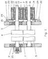
- the electric motors 1; 2 are each with their rotor 13; 14 on the pin 15; 16 of the forme cylinder 4; 4 'or transfer cylinder 5; 5 'attached and with their stator 17; 18 via a torque arm 19; 20 a radial and axial adjustment and changeable inclination of the respective printing cylinder as its printing on and off, side register and diagonal register adjustment enabling connected to the wall 21 (Fig. 1).
- the stator 17 in the form of an attachment 22 attached to it is equipped with a radially extending guide 23 into which a bolt 24 attached to the wall 21 engages in the direction of the axial adjustment of the pressure cylinder (FIG. 1).
- Fig. 1 there is the possibility of synchronously laterally shifting the transfer cylinder 5 with the forme cylinder 4 by a mechanical or electromotive adjustment of the two printing cylinders (not shown) for constant congruent ink transfer.
- this is not necessary for conventional offset printing, so that, according to the dash-dotted representation, the stator 18 can be fastened to the wall 21 via a flange 29 while saving the torque support 20.
- Fig. 5 shows a variant of a torque support, in which the stator 17 'via a in two ball joints 30; 31 mounted coupling 32 is connected to the wall.
Abstract
Description
- Die Erfindung betrifft eine Anordnung eines Elektromotors zum Antrieb eines Drehkörpers nach dem Oberbegriff von Anspruch 1.
- Aus der DE 41 38 479 C2 ist eine derartige Anordnung bekannt, bei der der Drehkörper innerhalb der Wandung mit exzentrisch ausgelenkt geführter Drehachse drehgelagert ist und eine Nachführeinrichtung auf den an der Wandung steif und ortsfest abgestützten Stator dergestalt einwirkend angeordnet ist, daß er die Drehkörper/Rotorverstellbewegung entsprechend nachvollzieht. Schließlich ist der mit dem Drehkörper fest verbundene Rotor gegenüber dem ortfesten Stator axial verschiebbar gestaltet.
- Der Nachteil der genannten Anordnung ist, daß insbesondere die Nachführeinrichtung für den Stator einen relativ großen technischen Aufwand erfordert und der Elektromotor dem Anwendungsfall angepaßt speziell gestaltet werden muß.
- Der Erfindung liegt die Aufgabe zugrunde, eine Anordnung eines Elektromotors zum Antrieb eines Drehkörpers gemäß dem Oberbegriff von Anspruch 1 zu schaffen, die in einfacher Weise mit geringem Aufwand die Verstellbarkeit des Drehkörpers, insbesondere die Druckan- und -abstellung und die Seiten- und Diagonalregisterverstellungen eines Druckzylinders ermöglicht. Die Aufgabe wird durch die kennzeichnenden Merkmale von Anspruch 1 erfüllt.
- Die Erfindung ermöglicht in einfacher Weise ein radiales Verschwenken des Drehkörpers, insbesondere die Druckan- und -abstellung eines Druckzylinders, sowie die axiale Verschiebung des Drehkörpers und Schiefstellung dessen Drehachse, insbesondere zur Verstellung des Seiten- und Diagonalregisters des Druckzylinders.
- Weitere vorteilhafte Ausgestaltungen der Erfindung sind in den Unteransprüchen enthalten.
- Die Erfindung wird nachfolgend an einem Ausführungsbeispiel näher erläutert. In den zugehörigen Zeichnungen zeigen in schematischer Darstellung:
- Fig. 1:
- zwei einzeln durch jeweils einen Elektromotor angetriebene Druckzyzylinder eines Druckwerkes
- Fig. 2:
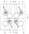
- ein aus 8 Druckzylindern bestehendes Druckwerk für einen indirekten, maximal zweiseitigen doppelten Druck
- Fig. 3:
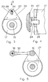
- eine den Stator des Elektromotors mit der Wandung verbindende Drehmomentenstütze
- Fig. 4:
- Ansicht X von Fig. 3, 90° gedreht
- Fig. 5:
- eine Variante gemäß Fig. 3
- Die nachfolgenden Erläuterungen sind auf die gleich gestaltete untere rechte Zylindergruppe 8 und die zwei linken, abweichend jeweils mit einem druckan- und -abstellbaren Übertragungszylinder 9; 9' und einem ortsfest gelagerten Formzylinder 10; 10' ausgestatteten Zylindergruppen 11; 12 übertragbar (Fig. 2).
- Die Elektromotoren 1; 2 sind jeweils mit ihrem Rotor 13; 14 auf dem Zapfen 15; 16 des Formzylinders 4; 4' bzw. Übertragungszylinders 5; 5' befestigt und mit ihrem Stator 17; 18 über eine Drehmomentenstütze 19; 20 eine radiale und axiale Verstellung sowie veränderbare Schiefstellung des jeweiligen Druckzylinders als dessen Druckan- und -abstellung, Seitenregister- sowie Diagonalregisterverstellung ermöglichend mit der Wandung 21 verbunden (Fig. 1).
- Gemäß Fig. 3 ist der Stator 17 in Gestalt eines an ihm befestigten Ansatzstückes 22 mit einer radial verlaufenden Führung 23 ausgestattet, in die ein an der Wandung 21 befestigter Bolzen 24 in Richtung der axialen Verstellung des Druckzylinders eingreift (Fig. 1). Damit wird in einfacher Weise sowohl die Verstellung des Seitenregisters des Formzylinders 4 mit Hilfe eines in Fig. 1 dargestellten Stelltriebes 25 als auch die Druckan- und -abstellung durch eine beiderseitige Verdrehung der Exzenterbuchsen 3; 3' mit Hilfe eines druckmittelbetriebenen Arbeitszylinders 26 (Fig. 2) ermöglicht, wobei stellmittelbedingt die Radialbewegung des Stators 17 von einer Schwenkbewegung überlagert ist.
- Auch kann durch eine geregelte unterschiedliche Verdrehung der Exzenterbuchsen 3; 3' auf beiden Seiten des Formzylinders 4 eine Verstellung des Diagonalregisters vorgenommen werden (Fig. 1). Um die damit verbundene Schiefstellung α des Stators 17 zu ermöglichen, sind die beiden Führungsflächen 27; 28 für den Bolzen 24 gekrümmt (Fig. 4).
- In Fig. 1 besteht die Möglichkeit, den Übertragungszylinder 5 mit dem Formzylinder 4 durch eine nicht darstellte mechanische oder elektromotorische Verstellung beider Druckzylinder für eine ständige deckungsgleiche Farbübertragung synchron seitlich zu verschieben. Dies ist jedoch für den gängigen Offsetdruck nicht erforderlich, so daß gemäß strichpunktierter Darstellung der Stator 18 unter Einsparung der Drehmomentenstütze 20 über einen Flansch 29 an der Wandung 21 befestigt werden kann.
- Fig. 5 zeigt als Variante eine Drehmomentenstütze, bei der der Stator 17' über eine in zwei Kugelgelenken 30; 31 gelagerte Koppel 32 mit der Wandung verbunden ist.
Claims (5)
- Anordnung eines Elektromotors zum Antrieb eines Drehkörpers, insbesondere als Druckzylinder einer Rotationsdruckmaschine, der bezüglich seiner Drehachse radial, axial und schräg oder in wahlweiser Kombination dieser Bewegungsrichtungen verstellbar in einer Wandung drehgelagert ist, wobei der Rotor des Elektromotors mit dem Drehkörper zu dessen Direktantrieb starr verbunden ist, gekennzeichnet dadurch, daß der Stator (17; 17'; 18) des Elektromotors (1; 2) über eine die Verstellbewegungen des Drehkörpers ermöglichende Drehmomentenstütze (19; 20) mit der Wandung (21) verbunden ist.
- Anordnung nach Anspruch 1, gekennzeichnet dadurch, daß der Stator (17; 18) mit einer radialen Führung (23) ausgestattet ist, in die ein mit der Wandung (21) fest verbundener Bolzen (24) in Richtung der axialen Verstellbewegung des Drehkörpers eingreift.
- Anordnung nach Anspruch 2, gekennzeichnet dadurch, daß die Führungsflächen (27; 28) für den Bolzen (24) eine schräge Verstellung des Drehkörpers ermöglichend gekrümmt sind.
- Anordnung nach Anspruch 1, gekennzeichnet dadurch, daß der Stator (17') über eine Koppel (32) an die Wandung angelenkt ist.
- Anordnung nach Anspruch 4, gekennzeichnet dadurch, daß die Gelenke der Koppel (32) deren räumliches Verschwenken ermöglichend, insbesondere als Kugelgelenke (30; 31) ausgebildet sind.
Applications Claiming Priority (2)
| Application Number | Priority Date | Filing Date | Title |
|---|---|---|---|
| DE4422097 | 1994-06-24 | ||
| DE4422097A DE4422097A1 (de) | 1994-06-24 | 1994-06-24 | Anordnung eines Elektromotors zum Antrieb eines Drehkörpers |
Publications (3)
| Publication Number | Publication Date |
|---|---|
| EP0689277A2 true EP0689277A2 (de) | 1995-12-27 |
| EP0689277A3 EP0689277A3 (de) | 1996-03-20 |
| EP0689277B1 EP0689277B1 (de) | 1998-02-11 |
Family
ID=6521387
Family Applications (1)
| Application Number | Title | Priority Date | Filing Date |
|---|---|---|---|
| EP95109296A Expired - Lifetime EP0689277B1 (de) | 1994-06-24 | 1995-06-16 | Anordnung eines Elektromotors zum Antrieb eines Drehkörpers |
Country Status (2)
| Country | Link |
|---|---|
| EP (1) | EP0689277B1 (de) |
| DE (2) | DE4422097A1 (de) |
Cited By (10)
| Publication number | Priority date | Publication date | Assignee | Title |
|---|---|---|---|---|
| EP0788879A1 (de) * | 1996-02-09 | 1997-08-13 | Bobst S.A. | Rotationsdruckmachine |
| EP0813959A1 (de) * | 1996-06-19 | 1997-12-29 | MAN Roland Druckmaschinen AG | Angetriebener Zylinder |
| WO2001086781A1 (en) * | 2000-05-05 | 2001-11-15 | Abb Research Ltd | Roll drive for moving rolls |
| WO2001086780A1 (en) * | 2000-05-05 | 2001-11-15 | Abb Research Ltd | Roll drive |
| EP1431034A3 (de) * | 2002-12-21 | 2004-09-15 | Koenig & Bauer Aktiengesellschaft | Vorrichtung zur Lageverstellung eines Drehkörpers mit Direktantrieb |
| DE102005050651A1 (de) * | 2005-10-20 | 2007-04-26 | Schaeffler Kg | Direktantrieb einer Druckmaschine |
| WO2007051660A1 (de) * | 2005-10-31 | 2007-05-10 | Koenig & Bauer Aktiengesellschaft | Antriebe eines rotierenden bauteils einer druckmaschine |
| EP1920925A2 (de) * | 2006-11-09 | 2008-05-14 | Robert Bosch Gmbh | Direktantrieb |
| WO2010115676A1 (de) | 2009-04-06 | 2010-10-14 | As Antriebstechnik & Service Gmbh | Drehmomentstütze |
| CN110254034A (zh) * | 2019-05-28 | 2019-09-20 | 温州立胜印刷包装机械有限公司 | 一种柔版印刷机用版辊装置 |
Families Citing this family (8)
| Publication number | Priority date | Publication date | Assignee | Title |
|---|---|---|---|---|
| JP3357074B2 (ja) * | 1996-08-09 | 2002-12-16 | ケーニツヒ ウント バウエル アクチエンゲゼルシヤフト | 胴駆動装置 |
| DE102004022774B4 (de) * | 2004-05-05 | 2015-09-17 | Koenig & Bauer Aktiengesellschaft | Anordnung eines Elektromotors zum Antrieb eines Zylinders einer Rotationsdruckmaschine |
| DE102004022775B4 (de) * | 2004-05-05 | 2014-09-18 | Koenig & Bauer Aktiengesellschaft | Anordnung eines Elektromotors zum Antrieb eines Drehkörpers |
| EP1882590A4 (de) * | 2005-05-20 | 2011-03-02 | Komori Printing Mach | Registereinstellvorrichtung eines drehkörpers |
| DE102007058282B4 (de) * | 2007-12-04 | 2015-01-22 | manroland sheetfed GmbH | Verfahren und Antrieb zum Antreiben einer Verarbeitungsmaschine für Bogenmaterial |
| DE102008044154A1 (de) * | 2008-11-28 | 2010-06-24 | Koenig & Bauer Aktiengesellschaft | Verfahren zur Einstellung des Diagonalregisters und/oder des Diagonalpassers einer Rotationsdruckmaschine |
| DE102009028204A1 (de) | 2009-08-04 | 2011-02-17 | Kba-Metronic Aktiengesellschaft | Diagonalregistereinstellvorrichtung |
| CN104300718A (zh) * | 2014-10-08 | 2015-01-21 | 中国化学工程第十三建设有限公司 | 电机支架 |
Citations (1)
| Publication number | Priority date | Publication date | Assignee | Title |
|---|---|---|---|---|
| DE4138479C2 (de) | 1991-11-22 | 1994-02-24 | Baumueller Nuernberg Gmbh | Verfahren und Anordnung für einen Elektromotor zum Antrieb eines Drehkörpers, insbesondere des druckgebenden Zylinders einer Druckmaschine |
Family Cites Families (10)
| Publication number | Priority date | Publication date | Assignee | Title |
|---|---|---|---|---|
| DE1240888B (de) * | 1958-11-28 | 1967-05-24 | Carl Allers Etablissement As | Vorrichtung zum axialen Hin- und Herbewegen einer Farbwalze |
| US3817174A (en) * | 1970-09-02 | 1974-06-18 | H Paulson | Printing press cylinder release system |
| US3945266A (en) * | 1974-11-06 | 1976-03-23 | Harris Corporation | Circumferential register assembly |
| DE3424349C2 (de) * | 1984-07-03 | 1995-05-04 | Heidelberger Druckmasch Ag | Vorrichtung zur Erfassung der Stellung eines Stellelements einer Druckmaschine |
| DE8513219U1 (de) * | 1985-05-04 | 1986-05-22 | Heidelberger Druckmaschinen Ag, 6900 Heidelberg | Elektromotor mit damit gekoppeltem mechanischem Getriebe |
| US5067403A (en) * | 1989-06-30 | 1991-11-26 | Man Roland Druckmaschinen Ag | Circumferential register adjustment system for a printing machine cylinder |
| NL9101165A (nl) * | 1991-07-04 | 1993-02-01 | Stork Brabant Bv | Sjabloonaandrijving voor een zeefdrukmachine. |
| DE9115598U1 (de) * | 1991-09-09 | 1992-04-23 | Koenig & Bauer Ag, 8700 Wuerzburg, De | |
| JP2585995Y2 (ja) * | 1992-10-01 | 1998-11-25 | 株式会社小森コーポレーション | 胴着脱装置 |
| DE4241567A1 (de) * | 1992-12-10 | 1994-06-16 | Roland Man Druckmasch | Vorrichtung zur Druckeinstellung eines mit einer aufschiebbaren Hülse ausgestatteten Druckzylinders |
-
1994
- 1994-06-24 DE DE4422097A patent/DE4422097A1/de not_active Withdrawn
-
1995
- 1995-06-16 EP EP95109296A patent/EP0689277B1/de not_active Expired - Lifetime
- 1995-06-16 DE DE59501429T patent/DE59501429D1/de not_active Expired - Lifetime
Patent Citations (1)
| Publication number | Priority date | Publication date | Assignee | Title |
|---|---|---|---|---|
| DE4138479C2 (de) | 1991-11-22 | 1994-02-24 | Baumueller Nuernberg Gmbh | Verfahren und Anordnung für einen Elektromotor zum Antrieb eines Drehkörpers, insbesondere des druckgebenden Zylinders einer Druckmaschine |
Cited By (18)
| Publication number | Priority date | Publication date | Assignee | Title |
|---|---|---|---|---|
| EP0788879A1 (de) * | 1996-02-09 | 1997-08-13 | Bobst S.A. | Rotationsdruckmachine |
| US5771805A (en) * | 1996-02-09 | 1998-06-30 | Bobat Sa | Rotating printing machine |
| EP0813959A1 (de) * | 1996-06-19 | 1997-12-29 | MAN Roland Druckmaschinen AG | Angetriebener Zylinder |
| US5832821A (en) * | 1996-06-19 | 1998-11-10 | Man Roland Druckmaschinen Ag | Driven cylinder |
| WO2001086781A1 (en) * | 2000-05-05 | 2001-11-15 | Abb Research Ltd | Roll drive for moving rolls |
| WO2001086780A1 (en) * | 2000-05-05 | 2001-11-15 | Abb Research Ltd | Roll drive |
| EP1431034A3 (de) * | 2002-12-21 | 2004-09-15 | Koenig & Bauer Aktiengesellschaft | Vorrichtung zur Lageverstellung eines Drehkörpers mit Direktantrieb |
| US7576464B2 (en) | 2005-10-20 | 2009-08-18 | Schaeffler Kg | Direct drive for a printing machine |
| EP1777068A3 (de) * | 2005-10-20 | 2008-01-23 | Schaeffler KG | Direktantrieb einer Druckmaschine |
| DE102005050651A1 (de) * | 2005-10-20 | 2007-04-26 | Schaeffler Kg | Direktantrieb einer Druckmaschine |
| WO2007051660A1 (de) * | 2005-10-31 | 2007-05-10 | Koenig & Bauer Aktiengesellschaft | Antriebe eines rotierenden bauteils einer druckmaschine |
| EP1920925A2 (de) * | 2006-11-09 | 2008-05-14 | Robert Bosch Gmbh | Direktantrieb |
| DE102006052763A1 (de) * | 2006-11-09 | 2008-05-15 | Robert Bosch Gmbh | Direktantrieb |
| US7854198B2 (en) | 2006-11-09 | 2010-12-21 | Robert Bosch Gmbh | Direct drive |
| EP1920925A3 (de) * | 2006-11-09 | 2010-12-22 | Robert Bosch Gmbh | Direktantrieb |
| WO2010115676A1 (de) | 2009-04-06 | 2010-10-14 | As Antriebstechnik & Service Gmbh | Drehmomentstütze |
| CN110254034A (zh) * | 2019-05-28 | 2019-09-20 | 温州立胜印刷包装机械有限公司 | 一种柔版印刷机用版辊装置 |
| CN110254034B (zh) * | 2019-05-28 | 2021-04-20 | 温州立胜印刷包装机械有限公司 | 一种柔版印刷机用版辊装置 |
Also Published As
| Publication number | Publication date |
|---|---|
| EP0689277A3 (de) | 1996-03-20 |
| EP0689277B1 (de) | 1998-02-11 |
| DE4422097A1 (de) | 1996-01-04 |
| DE59501429D1 (de) | 1998-03-19 |
Similar Documents
| Publication | Publication Date | Title |
|---|---|---|
| EP0689277A2 (de) | Anordnung eines Elektromotors zum Antrieb eines Drehkörpers | |
| DE4138479C2 (de) | Verfahren und Anordnung für einen Elektromotor zum Antrieb eines Drehkörpers, insbesondere des druckgebenden Zylinders einer Druckmaschine | |
| EP1336479B1 (de) | Antrieb eines rotierenden Bauteils einer Druckmaschine | |
| DE19521827A1 (de) | Druckmaschinen-Direktantrieb | |
| DE60221326T2 (de) | Druckvorrichtung, insbesondere flexographische Druckmaschine | |
| DE4143597C2 (de) | Druckmaschine mit wenigstens einem elektromotorisch angetriebenen, axial verstellbaren Zylinder oder sonstigen Drehkörper | |
| DE10219903B4 (de) | Zylinder einer Rotationsdruckmaschine | |
| EP1431034B1 (de) | Vorrichtung zur Lageverstellung eines Drehkörpers mit Direktantrieb | |
| DE10102734B4 (de) | Vorrichtung zum Antreiben einer Reibwalze in einer Druckmaschine | |
| EP0663291B1 (de) | Vorrichtung zur Druckeinstellung eines mit einer aufschiebbaren Hülse ausgestatteten Druckzylinders | |
| EP0722831B1 (de) | Verfahren und Anordnung für einen Elektromotor zum Antrieb eines Drehkörpers, insbesondere des druckgebenden Zylinders einer Druckmaschine | |
| DE10132156B4 (de) | Bahnstabilisierung zur berührungslosen Bahnführung bei fliegend wechselbaren Druckeinheiten | |
| EP0267504B1 (de) | Lagerung für changierende Auftragwalzen von Druckmaschinen | |
| EP0352625B1 (de) | Bogenfalzeinrichtung fuer eine Druckmaschine | |
| EP1000737B1 (de) | Druckmaschine | |
| EP0480879B1 (de) | Vorrichtung zur stufenlosen Verstellung der axialen Verreibungsbewegung von Reibwalzen | |
| DE19635796C2 (de) | Befestigung für einen Drehgeber | |
| EP1336481B1 (de) | Vorrichtung zur Umstellung der Greifersteuerung einer Wendetrommel | |
| DE102006053473B4 (de) | Anordnung eines Lagegebers auf einer Welle eines antreibbaren Zylinders in einer Verarbeitungsmaschine | |
| DE102008001003B3 (de) | Bedruckstoff verarbeitende Rotationsdruckmaschine | |
| DE102004019019A1 (de) | Bogen-Rotationsdruckmaschine für den Trockenoffsetdruck mit Kurzfarbwerk in Satellitenbauform (Satellitenbauart) | |
| DE102007011045A1 (de) | Druckmaschine | |
| DD253009A1 (de) | Bogengreifereinrichtung | |
| WO2001003929A1 (de) | Antriebslagerung von rotierenden werkzeugen in druckmaschinen | |
| DE102022102028A1 (de) | Verarbeitungswerk und Verfahren zum Betreiben eines Verarbeitungswerkes einer Verarbeitungsmaschine |
Legal Events
| Date | Code | Title | Description |
|---|---|---|---|
| PUAI | Public reference made under article 153(3) epc to a published international application that has entered the european phase |
Free format text: ORIGINAL CODE: 0009012 |
|
| AK | Designated contracting states |
Kind code of ref document: A2 Designated state(s): CH DE FR GB LI SE |
|
| PUAL | Search report despatched |
Free format text: ORIGINAL CODE: 0009013 |
|
| AK | Designated contracting states |
Kind code of ref document: A3 Designated state(s): CH DE FR GB LI SE |
|
| 17P | Request for examination filed |
Effective date: 19960719 |
|
| GRAG | Despatch of communication of intention to grant |
Free format text: ORIGINAL CODE: EPIDOS AGRA |
|
| 17Q | First examination report despatched |
Effective date: 19970401 |
|
| GRAG | Despatch of communication of intention to grant |
Free format text: ORIGINAL CODE: EPIDOS AGRA |
|
| GRAH | Despatch of communication of intention to grant a patent |
Free format text: ORIGINAL CODE: EPIDOS IGRA |
|
| GRAH | Despatch of communication of intention to grant a patent |
Free format text: ORIGINAL CODE: EPIDOS IGRA |
|
| GRAA | (expected) grant |
Free format text: ORIGINAL CODE: 0009210 |
|
| RAP1 | Party data changed (applicant data changed or rights of an application transferred) |
Owner name: MAN ROLAND DRUCKMASCHINEN AG |
|
| AK | Designated contracting states |
Kind code of ref document: B1 Designated state(s): CH DE FR GB LI SE |
|
| REG | Reference to a national code |
Ref country code: CH Ref legal event code: NV Representative=s name: E. BLUM & CO. PATENTANWAELTE Ref country code: CH Ref legal event code: EP |
|
| REF | Corresponds to: |
Ref document number: 59501429 Country of ref document: DE Date of ref document: 19980319 |
|
| ET | Fr: translation filed | ||
| GBT | Gb: translation of ep patent filed (gb section 77(6)(a)/1977) |
Effective date: 19980508 |
|
| PLBE | No opposition filed within time limit |
Free format text: ORIGINAL CODE: 0009261 |
|
| STAA | Information on the status of an ep patent application or granted ep patent |
Free format text: STATUS: NO OPPOSITION FILED WITHIN TIME LIMIT |
|
| 26N | No opposition filed | ||
| REG | Reference to a national code |
Ref country code: GB Ref legal event code: IF02 |
|
| REG | Reference to a national code |
Ref country code: CH Ref legal event code: PFA Owner name: MAN ROLAND DRUCKMASCHINEN AG Free format text: MAN ROLAND DRUCKMASCHINEN AG#POSTFACH 10 12 64#63012 OFFENBACH (DE) -TRANSFER TO- MAN ROLAND DRUCKMASCHINEN AG#POSTFACH 10 12 64#63012 OFFENBACH (DE) |
|
| REG | Reference to a national code |
Ref country code: CH Ref legal event code: PFA Owner name: MANROLAND AG Free format text: MAN ROLAND DRUCKMASCHINEN AG#POSTFACH 10 12 64#63012 OFFENBACH (DE) -TRANSFER TO- MANROLAND AG#MUEHLHEIMER STRA?E 341#63075 OFFENBACH (DE) |
|
| REG | Reference to a national code |
Ref country code: FR Ref legal event code: CD |
|
| PGFP | Annual fee paid to national office [announced via postgrant information from national office to epo] |
Ref country code: CH Payment date: 20110623 Year of fee payment: 17 Ref country code: SE Payment date: 20110613 Year of fee payment: 17 Ref country code: FR Payment date: 20110630 Year of fee payment: 17 |
|
| PGFP | Annual fee paid to national office [announced via postgrant information from national office to epo] |
Ref country code: GB Payment date: 20110620 Year of fee payment: 17 |
|
| PGFP | Annual fee paid to national office [announced via postgrant information from national office to epo] |
Ref country code: DE Payment date: 20120622 Year of fee payment: 18 |
|
| REG | Reference to a national code |
Ref country code: DE Ref legal event code: R081 Ref document number: 59501429 Country of ref document: DE Owner name: MANROLAND WEB SYSTEMS GMBH, DE Free format text: FORMER OWNER: MANROLAND AG, 63075 OFFENBACH, DE Effective date: 20120626 |
|
| REG | Reference to a national code |
Ref country code: SE Ref legal event code: EUG |
|
| REG | Reference to a national code |
Ref country code: CH Ref legal event code: PL |
|
| REG | Reference to a national code |
Ref country code: CH Ref legal event code: PL |
|
| GBPC | Gb: european patent ceased through non-payment of renewal fee |
Effective date: 20120616 |
|
| PG25 | Lapsed in a contracting state [announced via postgrant information from national office to epo] |
Ref country code: SE Free format text: LAPSE BECAUSE OF NON-PAYMENT OF DUE FEES Effective date: 20120617 |
|
| REG | Reference to a national code |
Ref country code: FR Ref legal event code: ST Effective date: 20130228 |
|
| PG25 | Lapsed in a contracting state [announced via postgrant information from national office to epo] |
Ref country code: GB Free format text: LAPSE BECAUSE OF NON-PAYMENT OF DUE FEES Effective date: 20120616 Ref country code: CH Free format text: LAPSE BECAUSE OF NON-PAYMENT OF DUE FEES Effective date: 20120630 Ref country code: LI Free format text: LAPSE BECAUSE OF NON-PAYMENT OF DUE FEES Effective date: 20120630 Ref country code: FR Free format text: LAPSE BECAUSE OF NON-PAYMENT OF DUE FEES Effective date: 20120702 |
|
| REG | Reference to a national code |
Ref country code: DE Ref legal event code: R119 Ref document number: 59501429 Country of ref document: DE Effective date: 20140101 |
|
| PG25 | Lapsed in a contracting state [announced via postgrant information from national office to epo] |
Ref country code: DE Free format text: LAPSE BECAUSE OF NON-PAYMENT OF DUE FEES Effective date: 20140101 |