EP0684585A2 - Bilderzeugungsverfahren und -gerät - Google Patents
Bilderzeugungsverfahren und -gerät Download PDFInfo
- Publication number
- EP0684585A2 EP0684585A2 EP95302680A EP95302680A EP0684585A2 EP 0684585 A2 EP0684585 A2 EP 0684585A2 EP 95302680 A EP95302680 A EP 95302680A EP 95302680 A EP95302680 A EP 95302680A EP 0684585 A2 EP0684585 A2 EP 0684585A2
- Authority
- EP
- European Patent Office
- Prior art keywords
- image
- viewpoint
- pixel
- pixels
- images
- Prior art date
- Legal status (The legal status is an assumption and is not a legal conclusion. Google has not performed a legal analysis and makes no representation as to the accuracy of the status listed.)
- Granted
Links
Images


Classifications
-
- G—PHYSICS
- G06—COMPUTING; CALCULATING OR COUNTING
- G06T—IMAGE DATA PROCESSING OR GENERATION, IN GENERAL
- G06T15/00—3D [Three Dimensional] image rendering
- G06T15/10—Geometric effects
-
- G—PHYSICS
- G06—COMPUTING; CALCULATING OR COUNTING
- G06T—IMAGE DATA PROCESSING OR GENERATION, IN GENERAL
- G06T15/00—3D [Three Dimensional] image rendering
- G06T15/10—Geometric effects
- G06T15/20—Perspective computation
-
- G—PHYSICS
- G06—COMPUTING; CALCULATING OR COUNTING
- G06T—IMAGE DATA PROCESSING OR GENERATION, IN GENERAL
- G06T15/00—3D [Three Dimensional] image rendering
- G06T15/10—Geometric effects
- G06T15/20—Perspective computation
- G06T15/205—Image-based rendering
-
- G—PHYSICS
- G06—COMPUTING; CALCULATING OR COUNTING
- G06T—IMAGE DATA PROCESSING OR GENERATION, IN GENERAL
- G06T7/00—Image analysis
- G06T7/97—Determining parameters from multiple pictures
-
- G—PHYSICS
- G06—COMPUTING; CALCULATING OR COUNTING
- G06V—IMAGE OR VIDEO RECOGNITION OR UNDERSTANDING
- G06V10/00—Arrangements for image or video recognition or understanding
- G06V10/10—Image acquisition
- G06V10/12—Details of acquisition arrangements; Constructional details thereof
- G06V10/14—Optical characteristics of the device performing the acquisition or on the illumination arrangements
- G06V10/147—Details of sensors, e.g. sensor lenses
Definitions
- the present invention relates to an image processing method and apparatus for generating an image from the viewpoint of an observer on the basis of images obtained from a plurality of viewpoints.
- a stereoscopic display As an apparatus for stereoscopically displaying images viewed from a plurality of viewpoints, a stereoscopic display, a lenticular display, and the like are known.
- the stereoscopic display displays images which are obtained from two cameras, and are alternately switched at a high speed. An observer can stereoscopically observe the displayed image using shutter glasses which is synchronized with the switching operation of the images or polarization glasses.
- images from, e.g., four cameras are re-arranged in units of pixels, and by adhering a lenticular sheet to the front surface, an image at four viewpoints can be stereoscopically expressed.
- the above-mentioned conventional stereoscopic display only a stereoscopic image in the photographing directions of the cameras upon photographing of an image can be observed. More specifically, since the two cameras are fixed in position to photograph an object, an observer observes only an identical image even when he or she moves his or her viewpoint (the positions of the eyes), and viewpoint movement on the observer side is not reflected in a displayed image, resulting in an unnatural image.
- the lenticular display can cope with movement of the viewpoint of the observer in the right-and-left direction, but cannot cope with continuous viewpoint movement since it allows only sequential observation of discrete images from the cameras.
- the viewpoint cannot be moved in the back-and-forth direction, i.e., a direction along the line of sight.
- a viewpoint movement in the back-and-forth direction is realized only when a stereoscopic view is achieved based on images generated by computer graphics.
- images generated by computer graphics are special ones since they are simple and the coordinate values, in a corresponding three-dimensional space, of all the points in images are known. For this reason, the possibility of a viewpoint movement in the back-and-forth direction has not been examined so far when images photographed by the cameras are to be stereoscopically observed.
- the present invention has been made in consideration of the above-mentioned prior arts, and has as one object to provide an image display apparatus and method, which can display an image from a desired viewpoint such as an image from a viewpoint which continuously moves upon movement of an observer.
- the present invention aims to provide an image display apparatus which generates and displays an image having sharpness of an original image when an image is displayed from a desired viewpoint on the basis of multi-viewpoint images.
- the invention aims to provide an image display apparatus and method, which can display an image in correspondence with the position of a viewpoint even when the viewpoint moves in a direction along a line of sight which is used for generating the displayed image.
- an image processing method of the present invention comprises the following arrangement.
- An image processing method comprises: the detection step of detecting correspondences among pixels between each two adjacent images of multi-viewpoint images; the first generation step of generating pixels constituting an interpolated images on the basis of the detected correspondences; and the construction step of constructing the interpolated image on the basis of the pixels generated in the first generation step.
- an image processing method for processing multi-viewpoint images comprises: the viewpoint detection step of detecting a position of a viewpoint; the generation step of generating, on the basis of the multi-viewpoint images, an image which has, as a virtual viewpoint, an intersecting point between a line of sight from the viewpoint detected in the viewpoint detection step and a viewpoint array corresponding to the multi-viewpoint images; and the correction step of correcting a distortion of an image caused by a deviation between the viewpoint detected in the viewpoint detection step and the virtual viewpoint on the basis of an amount of the deviation.
- an image processing method comprises: the detection step of detecting correspondences among pixels between each two adjacent images of multi-viewpoint images; the first generation step of generating pixels constituting an interpolated image on the basis of the detected correspondences; the estimation step of estimating correspondences among non-processed pixels, from which correspondences cannot be detected in the detection step, between each two adjacent images of the multi-viewpoint images; the second generation step of further generating pixels constituting the interpolated image on the basis of the correspondences estimated in the estimation step; and the construction step of constructing the interpolated image on the basis of the pixels generated in the first generation step.
- an image processing method comprises: the detection step of detecting correspondences among pixels between each two adjacent images of multi-viewpoint images; the generation step of generating pixels constituting an interpolated image on the basis of the detected correspondences; and the construction step of constructing the interpolated image on the basis of the pixels generated in the generation step, wherein the detection step includes the step of ignoring a correspondence between a pixel of interest and a corresponding pixel when the corresponding pixel which has the correspondence with the pixel of interest also has a correspondence with another pixel, and the number of correspondences for the pixel of interest is larger than the number of correspondences for the corresponding pixel.
- An image processing apparatus of the present invention comprises the following arrangement.
- An image processing apparatus comprises: detection means for detecting correspondences among pixels between each two adjacent images of multi-viewpoint images; first generation means for generating pixels constituting an interpolated images on the basis of the detected correspondences; and construction means for constructing the interpolated image on the basis of the pixels generated by the first generation means.
- an image processing apparatus for processing multi-viewpoint images comprises: viewpoint detection means for detecting a position of a viewpoint; generation means for generating, on the basis of the multi-viewpoint images, an image which has, as a virtual viewpoint, an intersecting point between a line of sight from the viewpoint detected by the viewpoint detection means and a viewpoint array corresponding to the multi-viewpoint images; and correction means for correcting a distortion of an image caused by a deviation between the viewpoint detected by the viewpoint detection means and the virtual viewpoint on the basis of an amount of the deviation.
- an image processing apparatus comprises: detection means for detecting correspondences among pixels between each two adjacent images of multi-viewpoint images; first generation means for generating pixels constituting an interpolated image on the basis of the detected correspondences; estimation means for estimating correspondences among non-processed pixels, from which correspondences cannot be detected by the detection means, between each two adjacent images of the multi-viewpoint images; second generation means for further generating pixels constituting the interpolated image on the basis of the correspondences estimated by the estimation means; and construction means for constructing the interpolated image on the basis of the pixels generated by the first generation means.
- an image processing apparatus comprises: detection means for detecting correspondences among pixels between each two adjacent images of multi-viewpoint images; generation means for generating pixels constituting an interpolated image on the basis of the detected correspondences; and construction means for constructing the interpolated image on the basis of the pixels generated by the generation means, wherein the detection means ignores a correspondence between a pixel of interest and a corresponding pixel when the corresponding pixel which has the correspondence with the pixel of interest also has a correspondence with another pixel, and the number of correspondences for the pixel of interest is larger than the number of correspondences for the corresponding pixel.
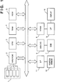
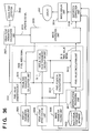
- Fig. 1 exemplifies an image processing apparatus which uses four cameras in an image input unit.
- an image input unit 1 includes four cameras, and inputs photographed images to the apparatus via an input port 2 as digital image signals.
- a CPU 3 is a processor for controlling the entire image processing apparatus, and executes predetermined control sequences by executing programs stored in a ROM 5 or a RAM 4.
- the RAM 4 and the ROM 5 also store data in addition to the programs.
- the RAM 4 stores digital image data input from the image input unit 1.
- a hard disk 7 exchanges data with the CPU 3, the RAM 4, and the like via a disk I/O port 6. Image data are also stored in the disk 7.
- Photographed image data or processed image data are developed on a VRAM 8, and are displayed on a stereoscopic display 10 via a video signal output I/F 9.
- a position sensor 12 detects the position of the viewpoint of an observer, and inputs detected information to the CPU 3 via a position sensor connection I/F 9.
- the four cameras are used.
- the present invention is not limited to the four cameras.
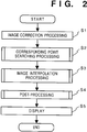
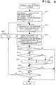
- Fig. 2 is a flow chart showing the control flow of processing for generating an interpolated image by the CPU 3 of this embodiment.
- Original images input from the image input unit 1 such as cameras are stored in the RAM 4 as digital image data.
- step S1 geometric correction processing of, e.g., the chromatic aberration and distortion of lenses, the deviation of the optical axis, the postures and positions of the cameras, and the like, and correction processing of any sensitivity nonuniformity of CCD sensors, and the like are executed.
- These correction processing operations can be performed at high speed by a table look-up operation if correction data are recorded in advance in the ROM 5 or the RAM 4 as calibration data. On the other hand, if correction data are obtained each time before images are input, correction can be more accurately achieved.
- step S2 Upon completion of these correction processing operations, the flow advances to step S2 to perform corresponding point searching (motion vector detection) processing among images.
- step S3 Upon completion of the corresponding point searching processing, the flow advances to step S3 to perform interpolation processing of images.
- step S4 The flow then advances to step S4 to estimate pixel values which could not be obtained in the interpolation processing.
- step S5 an image viewed from the viewpoint position is selected from the input images or interpolated images on the basis of information from the viewpoint position sensor, and the selected image is displayed on the stereoscopic display.
- An observer observes the image with glasses and the like, which match the system of the stereoscopic display.
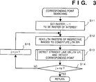
- Fig. 3 is a flow chart of the corresponding point searching processing in step S2.
- the first raster of each image is initially set to be the raster of interest.
- the raster of interest is represented by a raster j of interest (where j is the ordinal number of the raster of interest).
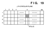
- step S12 rasters j of interest of the respective images are read out onto a work memory to virtually constitute a j-th epipolar plane image (EPI).
- an image constituted by juxtaposing identical lines extracted from multi-viewpoint images in turn is called an epipolar plane image.
- step S13 straight lines on which corresponding points are present are extracted, and the corresponding points are calculated from the extracted straight lines. The calculated points are stored.
- the detailed straight line detection algorithm will be described below with reference to the flow chart in Fig. 5.
- Formula (1) means to calculate pixels which are present on a straight line having the pixel of interest as an end point and an inclination m, and in each of which the square of an error from the pixel of interest is smaller than TH2.
- TH2 is a threshold value for finding the corresponding points, and is set to be 1200 in this embodiment.
- the difference value is set to be 20 to provide a given margin. For this reason, as the accuracy of the input system increases, the difference value becomes small. Conversely, if the input system has lower accuracy, a larger difference value must be set.
- nx is the number of pixels, in the main scanning direction, of an image, and N is the number of cameras.
- step S23 a corresponding point of the priority level n is calculated from the straight line of the inclination m calculated in step S22, and is stored in the memory. If a plurality of corresponding points are obtained, all the points are stored as corresponding points of the priority level n for the sake of simplicity. Pixels calculated as the corresponding points are set to be processed pixels. If the corresponding point calculated based on the straight line of the inclination m in step S23 has already been processed, this point is excluded from the corresponding points. Furthermore, the number of non-processed pixels is set in w.
- n representing the priority level is equal to P.
- P represents the complexity of a phenomenon in which objects conceal each other (occlusion). More specifically, if P is large, it represents a state wherein a large number of objects overlap each other; if P is small, the overlapping state of objects is small.
- step S14 it is checked if processing is performed for all the rasters of input images. If NO in step S14, the value j is incremented by one in step S15, and the flow returns to step S12; otherwise, the flow advances to step S3. Note that ny is the total number of rasters of input images.
- step S3 image interpolation processing is performed.
- the image interpolation processing is performed using the corresponding points calculated in step S2.
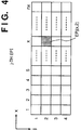
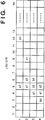
- Fig. 6 shows an example of the j-th epipolar plane image.
- a1 and b1 represent the corresponding points of priority level 1
- c2 represents corresponding points of priority level 2.
- n images are interpolated at equal intervals between input images.
- the number of interpolated images is assumed to be 2.
- two rasters are interpolated between each two adjacent lines of the epipolar plane image, and the pixel values of the interpolated rasters, which are present on straight lines connecting the corresponding points on the original epipolar plane image, can be set to be an average value of the corresponding points.
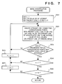
- This processing will be described below with reference to the flow chart in Fig. 7.
- step S52 a straight line connecting the corresponding points of the priority level n on the j-th EPI is assumed, and the pixel values of interpolated rasters, which are present on this straight line, are set to be an average value of pixel values on the original images present on the straight line. If there are a plurality of corresponding points with the same priority level, processing is performed in the order from a straight line connecting the corresponding points and having a smaller inclination (a straight line perpendicular to a raster is assumed to be one with an inclination "0").
- ny is the same as ny used in step S14 in Fig. 3, and represents the total number of rasters of input images.
- a , b, and c represent pixels interpolated based on the corresponding points a1, b1, and c2, respectively.
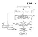
- step S4 post-processing is performed for the images which have been subjected to the interpolation processing in step S3. Pixels for which no corresponding points can be obtained even after the processing in step S3 are left without being interpolated. The values of pixels which are left without being interpolated are estimated by the post-processing. The flow of this processing will be explained below with reference to the flow chart in Fig. 9.
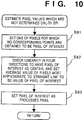
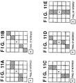
- step S72 to estimate the values of pixels whose values are not determined on the j-th EPI for interpolation in which rasters are interpolated. The estimation method will be explained below with reference to the flow chart in Fig. 10 while taking Figs. 11A to 11E as an example.
- one of pixels whose values are not determined on the j-th EPI for interpolation in which rasters are interpolated is set to be the pixel * of interest (step S81).
- 5 x 5 pixels having the pixel * of interest as the center are assumed, and a sum of differences between the pixel of interest and pixels located at hatched positions is calculated for each of pixels shown in Figs. 11A to 11E.
- the sums of the differences in Figs. 11A to 11E are compared, and an average value of the hatched pixels corresponding to the minimum sum is set to be an estimated value (step S82).
- the path of corresponding points on the EPI becomes a straight line with an inclination falling within a certain range. More specifically, when the EPI is constituted by juxtaposing input images in turn from one obtained by the left-end camera, the straight line extends obliquely upward from the left to the right, and its inclination becomes smaller (closer to a horizontal state) as the distance between the camera to an object is smaller. For this reason, by examining the straight line pattern which extends obliquely upward from the left to the right while changing its inclination, an unknown pixel can be estimated with higher accuracy than that estimated by simply calculating an average value of surrounding pixels. When images are juxtaposed in turn from the one obtained by the right-end camera, estimation is performed using mirror images of the patterns shown in Figs. 11A to 11E.
- step S73 the flow advances to step S73 to check if all the pixel values on the j-th EPI for interpolation in which rasters are interpolated are estimated.
- step S73 If YES in step S73, the flow advances to step S74; otherwise, the flow returns to step S72.
- step S74 it is checked if the processing is performed for all the EPIs. If NO in step S74, the next EPI is set as the EPI of interest (the value j is incremented by one), and the flow returns to step S72; otherwise, the post-processing ends, and the flow advances to step S5.
- an image corresponding to the viewpoint position is selected from the interpolated images and input images on the basis of the output from the viewpoint sensor 12, and the selected image is displayed in step S5.
- the observer can observe a stereoscopic image.
- the viewpoint position can be determined based on the camera interval.
- interpolated images can be generated by relating continuity between neighboring pixels as lines, high-quality interpolated images which are free from deterioration of edges, and the like can be generated, and an image from a viewpoint from which no images are photographed in practice can be displayed.
- the image input unit is not limited to one for inputting photographed images in real time, but may input images which are photographed in advance or may input images from a database which stores images created by, e.g., a computer. If a change in object over time can be ignored, such an object may be photographed by moving a single camera.
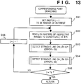
- Fig. 13 is a flow chart showing the corresponding point searching processing in which some steps in Fig. 3 are changed. Steps S91, S92, S93, S95, and S96 execute the same processing operations as in steps S11, S12, S13, S14, and S15, respectively.
- the above-mentioned variations in input images can be absorbed. Processing except for this corresponding point searching processing is as described above.
- step S94 a straight line constituted by points with larger errors than in step S93 can be detected. For this reason, even when images are blurred, corresponding points can be detected.
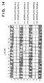
- 5 x 5 pixel blocks are defined to have the pixel * of interest in, e.g., Fig. 14 as the center.
- a raster used for estimating an unknown pixel value is selected from only original images. More specifically, in order to estimate the value of the pixel * of interest, a plane is constituted by juxtaposing rasters 1, 4, 5, 7, and 10 in turn to have a raster (the fifth raster in Fig. 14) where the pixel * of interest is present as the center. In this state, the same processing as in the estimation processing described above with reference to Figs. 10 to 11E is performed, thus preventing estimation errors from being accumulated.
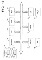
- Fig. 15 exemplifies an image processing apparatus which uses four cameras in an image input unit.
- an image input unit 33 includes four cameras 20 to 23, and inputs photographed images to the apparatus via an input port 24 as digital image signals.
- a CPU 25 is a processor for controlling the entire image processing apparatus, and executes predetermined control sequences by executing programs stored in a ROM 27 or a RAM 26.
- the RAM 26 and the ROM 27 also store data in addition to the programs.
- the RAM 26 stores digital image data input from the image input unit 33.
- a hard disk 29 exchanges data with the CPU 25, the RAM 26, and the like via a disk I/O port 28. Image data are also stored in the disk 29. Photographed image data or processed image data are developed on a VRAM 30, and are displayed on a stereoscopic display 32 via a video signal output I/F 31.
- the four cameras are used.
- the present invention is not limited to the four cameras.
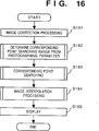
- Fig. 16 is a flow chart showing the flow of interpolated image generation processing by the image processing apparatus of this embodiment.
- step S161 original images input from the cameras 20 to 23 are subjected to geometric correction processing of, e.g., the chromatic aberration and distortion of lenses, the deviation of the optical axis, the postures and positions of the cameras, and the like, and correction processing of sensitivity nonuniformity of CCD sensors, and the like.
- These correction processing operations can be performed at high speed by a table look-up operation if correction data are recorded in advance in the ROM or RAM as calibration data. On the other hand, if correction data are obtained each time before images are input, correction can be more accurately achieved.
- the flow advances to step S162, and a range for corresponding point searching processing is determined based on photographing parameters.
- step S163 The flow then advances to step S163, and the corresponding point searching processing among images is performed using the determination result in step S162. Upon completion of the corresponding point searching processing, the flow advances to step S164, and image interpolation processing is performed. Thereafter, in step S165, corrected input images and interpolated images are displayed on a lenticular display.
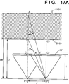
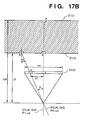
- Figs. 17A and 17B are views showing the calculation principle of the corresponding point searching range.
- S101 is the rearmost surface of a space to be photographed
- S103 is the frontmost surface of the space to be photographed
- the space between these surfaces is a photographing space ⁇ .
- Le is the distance to the rearmost surface of the space to be photographed
- Lf is the distance to the frontmost surface of the space to be photographed.
- the angle, ⁇ is an angle defined by a perpendicular from a photographing position pl to an imaging plane FP, and a straight line connecting between a photographing position p2 separated from the photographing position p1 by a distance d, and a photographing object a located on the frontmost surface S102 of the photographing space ⁇ .
- the angle, ⁇ is similarly an angle defined by a straight line connecting between a photographing object b located on the rearmost surface S101 of the photographing space ⁇ and the point p2, and a perpendicular from the viewpoint (photographing) position p1 to the imaging plane FP.
- the focal length, f is the distance between the photographing position and the imaging plane FP.
- Images a' and b' are images of the objects a and b on the imaging plane FP, which are photographed from the point p2. According to Fig. 17A, the distance between images a' and b' in the imaging plane as the corresponding point searching range is calculated.
- the moving distance, dl, on the imaging plane, of the frontmost object a in the photographing space ⁇ , which object is photographed from the photographing positions p1 and p2, is calculated.
- the moving distance dl is calculated using the following formula from Figs. 17A and 17B. Note that the number of pixels, in the main scanning direction (the lateral direction in Fig. 17A), of the imaging plane is represented by nx.
- Positions c1 and c2 are intersecting points of perpendiculars from the positions p1 and p2 to the imaging plane FP and the imaging plane FP, respectively.
- a position c3 is a intersecting position of a perpendicular from the position p2 to the rearmost surface S103 and rearmost surface S103.
- the positions c1 and c2 are centers of the imaging plane FP in the main scanning direction.
- the images are projected on the position cl of the imaging plane FP.
- the images of object a is projected on the position a' and the image of the object b is projected on the position b' of the imaging plane.
- an image viewed from the position p1 and an image viewed from the position p2 may deviate from each other by a minimum of d2 and a maximum of d1.
- the range of the inclination of a straight line for searching for corresponding points between images at the viewpoints p1 and p2 on an epipolar plane image can be changed between d1 and d2.
- the range for searching for corresponding points can be prevented from being inadvertently widened, and high-speed searching processing can be realized.
- the searching pitch is calculated based on the number of cameras, the searching processing time can be prevented from being prolonged by inadvertently setting a small searching pitch.
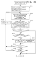
- Fig. 18 is a flow chart showing the corresponding point searching processing in step S162 in Fig. 16.
- step S181 the first raster of each image is initially set to be the raster of interest.
- step S182 the rasters of interest of the respective images are read out onto a work memory to virtually constitute a j-th epipolar plane image (EPI).
- EPI epipolar plane image
- step S183 When input devices (cameras) are set parallel to each other at equal intervals, all the corresponding points on the epipolar plane image align on straight lines. Therefore, corresponding points can be detected by detecting straight lines, and images can be interpolated on the detected straight lines. Thus, straight lines are detected in step S183, and corresponding points are calculated and stored based on the detected straight lines in step S184.
- the flow advances to step S202.
- the total number of detected straight lines is stored as L.
- TH2 is a threshold value for finding the corresponding points, and is set to be 1200 in this embodiment.
- the value "1200" has the following meaning.
- the above-mentioned technique is performed for each of R, G, and B pixel values.
- the above-mentioned technique can be applied when images are converted to various other colorimetric systems such as YIQ, HSI, and the like, and threshold values suitable therefor can be set and used.
- step S203 a corresponding point of the priority level n is calculated from the straight line of the inclination m calculated in step S202, and is stored in the memory as (n, f(L)) together with the value of a score f(L).
- L is the number of detected straight lines
- f() is a function indicating a small value when the number of straight lines is large, and indicating a large value when the number of straight lines is small.
- step S203 the number of non-processed pixels is set in w.
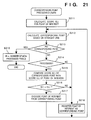
- Fig. 21 is a flow chart showing in more detail the processing in step S203.
- the score f(L) is calculated based on the straight line detected in-step S202 (S211). One corresponding point is obtained based on the straight line (S212). If no corresponding point is obtained, the number of non-processed pixels is set in w, and the processing in step S203 ends (S219). If a corresponding point is found, it is checked if the point has already been processed (S214). If the corresponding point is not processed yet, it is stored as a corresponding point (S218). If the corresponding point has already been processed, the score f(L') of the corresponding point is compared with the score f(L) of the point of interest (S215).
- step S203 ends.
- step S208 The flow then advances to step S208 to check if n representing the priority level is equal to P.
- P represents the complexity of a phenomenon in which objects conceal each other (occlusion). More specifically, if P is large, it represents a state wherein a large number of objects overlap each other; if P is small, the overlapping state of objects is small.
- step S209 the flow advances to step S209 to check if the number of non-processed pixels is smaller than that in the previous processing. If the number of non-processed pixels is smaller than that in the previous processing, the flow advances to step S210; otherwise, the straight line detection processing on the j-th EPI, i.e., step S184 in Fig. 18 ends.
- step S186 it is checked if processing is performed for all the rasters of input images. If NO in step S186, the value j is incremented by one, and the flow returns to step S182; otherwise, i.e., if step S163 in Fig. 16 ends, the flow advances to step S164.
- corresponding points which cannot be obtained from two images, can be obtained, and occlusion can also be dealt with. For this reason, the positional relationship between objects in the direction of the line of sight can be normally processed, and the accuracy of corresponding point searching processing can be improved.
- the number of straight lines detected based on a certain pixel of interest is expressed as a score indicating the probability of the pixel of interest being a corresponding point, and a more probable corresponding point is obtained by comparing scores. For this reason, the corresponding point searching processing can be performed without reversing the positional relationship between an object in a uniform color and a small object present in front of the former object in the direction of the line of sight.
- step S164 The flow advances to step S164 to perform image interpolation processing.
- the image interpolation processing is performed using the corresponding points obtained in step S163.
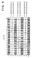
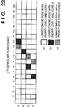
- the detailed algorithm will be explained below while taking Fig. 22 as an example.
- n images are interpolated at equal intervals between input images.
- the number n of interpolated lines is assumed to be 2.
- two lines are interpolated between each two adjacent lines of the EPI, and the pixel values of the interpolated lines, which are present on straight lines connecting the corresponding points on the original epipolar plane image, can be set to be an average value of the corresponding points.
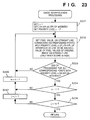
- Fig. 23 is a flow chart showing in detail the processing in step S164 in Fig. 16.
- step S232 a straight line connecting the corresponding points of the priority level n on the j-th EPI is assumed, and the pixel values of interpolated lines, which are present on this straight line, are set to be an average value of pixel values on the original images present on the straight line.
- the pixel value of the interpolated line can be overwritten.
- the score is lower, overwriting is inhibited.
- the pixel values of points a and b on straight lines connecting the corresponding points are set to be an average value of pixel values indicated by a1 and b1, respectively.
- a point at coordinates (11, 3) corresponds to both al and bl, but is set with an average value b of pixel values on the straight line as a corresponding point of bl with a higher score.
- step S233 to check if the processing in step S232 is completed for all the corresponding points with the priority level n on the EPI of interest. If NO in step S233, the flow returns to step S232; otherwise, the flow advances to step S234 to check if the priority level which is being processed currently is 1.
- a , b, and c represent pixels interpolated based on the corresponding points a1, b1, and c2, respectively.
- the parallax in the up-and-down direction is omitted.
- multi-viewpoint images photographed from photographing positions in a matrix pattern on a plane, which are separated by a relatively large viewpoint interval are held, these multi-viewpoint images are interpolated between viewpoints in the right-and-left direction, and are then interpolated between viewpoints in the up-and-down direction, thus generating images which take the parallax in the up-and-down direction into account.
- the straight line searching can be realized not only from the first line to the last line of the epipolar plane image but also from the last line to the first line.
- the searching range, the searching pitch, and the inclination of the straight line as the searching parameters for the latter searching process can be obtained by attaching opposite signs to those for the former searching process to achieve straight line searching in two directions. In this manner, when corresponding points are searched for upward and downward for one EPI, the corresponding point searching processing can be performed at higher speed.
- the viewpoint position of an observer can be detected and an image viewed from the observer can be re-constructed so as to cope with smooth up-and-down, back-and-forth, and right-and-left movements of the viewpoint of the observer.
- the parallax in the up-and-down direction is omitted in the following description.
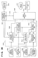
- Fig. 26 is a block diagram showing the arrangement of an image display apparatus according to the third embodiment of the present invention.
- reference numeral 2601 denotes a display screen which is fixed in position, and displays images;
- 2602 a viewpoint detector for detecting the position of the eye of a user who watches the display screen 2601;
- 2603 a multi-viewpoint image database which stores multi-viewpoint images obtained by photographing an object from viewpoints set on a plane at coarse intervals.
- Reference numeral 2604 denotes a display parameter holding unit which holds parameters associated with the display screen 2601; 2605, a viewpoint plane holding unit which holds the plane (viewpoint plane) where the viewpoints are set upon photographing of images to be stored in the image database 2603; and 2606, an image parameter holding unit which holds image parameters of the images stored in the image database 2603 and images interpolated using the stored images.
- Reference numeral 2607 denotes a viewpoint parameter calculation unit for calculating viewpoint parameters on the basis of a signal from the viewpoint detector 2602; 2608, an image generation unit for generating images corresponding to the movement of the viewpoint; 2609, an index signal indicating a pixel of interest; 2610, a line of sight parameter calculation unit for calculating the direction of the line of sight corresponding to the pixel indicated by the index signal 2609; 2611, a virtual viewpoint parameter calculation unit for calculating the intersecting point (virtual viewpoint) between the line of sight represented by the line of sight parameters and the viewpoint plane; 2612, a pixel position calculation unit for calculating a pixel position corresponding to the direction of the line of sight of an image at the virtual viewpoint on the basis of the line of sight parameters, the viewpoint plane, the virtual viewpoint parameters, and the image parameters; 2613, a pixel value calculation unit for calculating a corresponding pixel value on the basis of images held in the image database and images interpolated using the held images; and 2614, an image display unit for displaying images
- Reference numeral 2615 denotes an updating signal indicating that the viewpoint parameters are updated; and 2616, a pixel value signal indicating a pixel value.
- Reference numeral 2617 is an interpolation processing unit which is used in the second embodiment, and generates images at sufficiently fine viewpoint intervals using multi-viewpoint images photographed from viewpoints at coarse intervals.
- the line of sight parameter calculation unit 2610, the virtual viewpoint parameter calculation unit 2611, the pixel position calculation unit 2612, the pixel value calculation unit 2613, and the interpolation processing unit 2617 together constitute a pixel value generation unit 2618.
- the operation of the image display apparatus with the arrangement shown in Fig. 26 will be briefly described below.
- a signal from the viewpoint detector 2602 changes, and the viewpoint parameter calculation unit 2607 supplies an updating signal 2615 to the image generation unit 2608 in response to the change in signal.
- the image generation unit 2608 Upon reception of the updating signal 2615, the image generation unit 2608 begins to generate a new image corresponding to the viewpoint movement.
- the image generation unit 2608 acquires pixel value signals 2616 corresponding to index signals 2609 for all the pixels from the pixel value generation unit 2618.
- the pixel value generation unit 2618 acquires display parameters from the display parameter holding unit 2604, and calculates line of sight parameters corresponding to the index signals 2609.
- the virtual viewpoint parameter calculation unit 2611 acquires a viewpoint plane from the viewpoint plane holding unit 2605, and calculates virtual viewpoint parameters representing the intersecting point (virtual viewpoint) between the line of sight represented by the line of sight parameters, and the viewpoint plane.
- the pixel position calculation unit 2612 acquires image parameters from the image parameter holding unit 2606, and calculates a pixel position corresponding to the direction of the line of sight of an image at the virtual viewpoint position on the basis of the line of sight parameters, the viewpoint plane, and the virtual viewpoint parameters in addition to the acquired image parameters.
- the pixel value calculation unit 2613 calculates a corresponding pixel value signal 2616 from images from the image database 2603 and interpolated images generated by the interpolation processing unit 2617 based on the images from the database 2603 on the basis of the pixel position and the virtual viewpoint parameters.
- the image generation unit 2608 acquires pixel value signals 2616 for all the pixels from the pixel value calculation unit 2613, it sends the signals to the image display unit 2614.
- the image display unit 2614 displays the generated image corresponding to the new viewpoint on the display screen 2601.
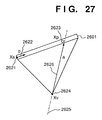
- Fig. 27 shows the calculation principle of the line of sight parameter calculation unit 2610.
- Reference numeral 2601 denotes a display screen; 2621, an end point (indicated by a position vector Xs) of the display screen 2601; 2622, a vector (indicated by a display screen vector p) which has a length matching the pixel pitch of the display screen 2601, and an inclination matching that of the display screen 2601; 2623, the position (indicated by a position vector Xp) of a pixel of interest on the display screen 2601; 2624, the viewpoint position (indicated by a position vector Xv) of a user; 2625, a line of sight corresponding to the position 2623 of the pixel of interest; and 2626, a line of sight vector (indicated by a vector a) representing the inclination of the line of sight 2625.
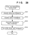
- Fig. 28 is a flow chart showing the processing of the line of sight parameter calculation unit 2610.
- viewpoint parameters are acquired from the viewpoint parameter calculation unit 2607.
- the viewpoint parameters include the viewpoint position 2624 of the user shown in Fig. 27.
- display parameters are acquired from the display parameter holding unit 2604.
- the display parameters include the end point 2621 (vector Xs) of the display screen 2601, and the display screen vector 2622 (vector p).
- the display screen vector 2622 is determined by the inclination, actual size, and pixel size of the display screen.
- step S284 line of sight parameters corresponding to the direction of the pixel position 2623 viewed from the viewpoint position 2624 are calculated.
- the line of sight parameters include a set (Xv, a) of the viewpoint position 2624 and the line of sight vector 2626.
- the line of sight parameter calculation unit 2610 calculates the line of sight parameters.
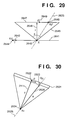
- Fig. 29 shows the calculation principle of the virtual viewpoint parameter calculation unit 2611 and the pixel position calculation unit 2612.
- Reference numeral 2625 denotes the line of sight; 2641, a straight line representing a viewpoint array included in the viewpoint plane upon photographing of multi-viewpoint images stored in the image database 2603; 2642, the intersecting point (virtual viewpoint; indicated by a position vector X) between the line of sight 2625 and the straight line 2641; 2643, a vector (indicated by a viewpoint array vector T) representing the inclination of the straight line 2641; and 2644, an end point (indicated by a position vector X1) of the straight line 2641.
- Reference numeral 2645 denotes a view field with a field angle ⁇ at the virtual viewpoint 2642; 2646, a vector (indicated by a focal point vector f) which has a length matching the focal length of the camera which photographs the multi-viewpoint images, and an inclination matching that of the camera; 2647, a virtual imaging plane at the virtual viewpoint 2642; 2648, a pixel position (indicated by a position vector Xp') as the intersecting point between the virtual imaging plane 2647 and the line of sight 2625; and 2649, a vector (indicated by an imaging plane vector p') which has a length matching the pixel pitch of the virtual imaging plane 2647 and has an inclination matching that of the virtual imaging plane 2647.
- viewpoint array vector 2643 and the end point 2644 of the straight line 2641 are held in the viewpoint plane holding unit 2605 as values representing a photographing viewpoint array.
- the focal point vector 2646 and the imaging plane vector 2649 are held in the image parameter holding-unit 2606 as image parameters.
- the focal point vector 2646 is determined by the focal length and the inclination of the camera which photographs multi-viewpoint images.
- the imaging plane vector 2649 is a vector which intersects the focal point vector 2646, and has a size equal to the cell size (the size of one pixel) of the imaging plane.
- the parameter t is calculated by solving formulas (6) and (7) to calculate the virtual viewpoint X.
- i' a pixel position parameter which uniquely represents the pixel position 2648
- ⁇ a coefficient of the direction of the line of sight.
- the parameter i' is calculated by solving formulas (8) and (9), and is used as the output from the pixel position calculation unit 2612.
- the image database 2603 holds a plurality of images obtained by photographing a single object from viewpoints at coarse intervals, and the interpolation processing unit 2617 obtains interpolated images which are interpolated at sufficiently fine intervals using the held images.
- the interpolation processing is performed in a manner described in the second embodiment.
- the interpolation processing unit 2617 generates an interpolated image based on the acquired image. Of this image, the value of a pixel at a position closest to the pixel position 2648 calculated by the pixel position calculation unit 2612 is acquired, and is output as the pixel value signal 2616.
- the parallax in the up-and-down direction is omitted for the sake of simplicity.
- a binocular stereoscopic display apparatus which can move the viewpoint in the up-and-down and right-and-left directions while taking the parallax in the up-and-down direction into account, can be realized by the above-mentioned method.
- the viewpoint parameter calculation unit 2607 calculates viewpoint parameters corresponding to the positions of the right and left eyes
- the image generation unit 2608 generates images presented for the right and left eyes
- a binocular stereoscopic display apparatus which can move the viewpoint in the back-and-forth, up-and-down, and right-and-left directions can be realized.
- the display screen 2601 in the third embodiment comprises a so-called a head-mounted display (HMD) which is fixed to the head portion of a user.
- HMD head-mounted display
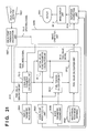
- Fig. 30 shows the calculation principle of the line of sight parameter calculation unit 2610 of this embodiment.
- Reference numeral 2601 denotes a display screen; 2622, a vector (display screen vector p) which has a length matching the pixel pitch of the display screen 2601, and an inclination matching that of the display screen 2601; 2623, the position (position vector Xp) of a pixel of interest on the display screen 2601; 2624, the viewpoint position (position vector Xv) of a user; 2111, a vector (front side vector F) from the viewpoint position 2624 to the central point on the display screen 2601; 2625, a line of sight corresponding to the position 2623 of the pixel of interest; and 2626, a line of sight vector (vector a ) representing the inclination of the line of sight 2625.
- the viewpoint detector 2602 detects the inclination in the direction of the front side, i.e., the inclination of the front side vector 2111 in addition to the position of the viewpoint 2624 of the user.
- the inclination of the display screen 2601 is determined by the inclination of the front side vector 2111 (normally, a right angle).
- the distance from the viewpoint position 2624 to the display screen 2601, i.e., the length of the front side vector 2111, and the pixel pitch, i.e., the length of the display screen vector 2622 have fixed values determined by the shape of the HMD, and these values are held in the display parameter holding unit 2604.
- an HMD type image display apparatus which can move and display multi-viewpoint image at an arbitrary viewpoint can be realized.
- an image display apparatus which can display an image moved to an arbitrary viewpoint can be realized by the same processing of the visual parameter calculation unit 2601 as in this embodiment.
- a viewpoint position input device for moving the viewpoint position 2624 on a reference coordinate system using, e.g., a steering wheel is used.
- multi-viewpoint images which are photographed in advance and images interpolated using the stored images are held in the image database 2603.
- the image database is replaced by a multi-eye television camera which can fetch multi-viewpoint images in real time, an arbitrary viewpoint image real-time photographing/display system can be realized.
- the apparatus of each of the above embodiment can generate interpolated images with high accuracy. Since corresponding point searching parameters are automatically determined, high-speed interpolation processing can be realized. By reconstructing images corresponding to the viewpoint movement in the back-and-forth direction using a large number of images generated by the interpolation processing or multi-viewpoint images photographed by moving a viewpoint at sufficiently fine intervals, a viewpoint movement in the back-and-forth direction, which cannot be realized by the conventional system, can be realized.
- the present invention may be applied to a stand-alone type image processing apparatus, a system such as a multi-viewpoint television system, a multi-viewpoint video telephone terminal, a multi-viewpoint video meeting system, and the like, or a composite apparatus as a combination of a computer and another image processing apparatus.
- Fig. 31 is a block diagram showing the arrangement of an image processing apparatus according to the fifth embodiment of the present invention.
- reference numeral 2601 denotes a display screen which is fixed in position, and displays images;
- 2602 a viewpoint detector for detecting the position of the eye of a user who watches the display screen 2601;
- 2603 a multi-viewpoint image database which stores multi-viewpoint images obtained by photographing an object from viewpoints set on a straight line at sufficiently fine intervals.
- Reference numeral 2604 denotes a display parameter holding unit which holds parameters associated with the display screen 2601; 2605, a viewpoint array holding unit which holds a straight line (to be referred to as a viewpoint array hereinafter) including the viewpoint array upon photographing of images to be stored in the image database 2603; and 2606, an image parameter holding unit which holds image parameters of multi-viewpoint images stored in the image database 2603.
- Reference numeral 2607 denotes a viewpoint parameter calculation unit for calculating viewpoint parameters on the basis of a signal from the viewpoint detector 2602; 2608, an image generation unit for generating images corresponding to the movement of the viewpoint; 2609, an index signal indicating a pixel of interest; 2610, a line of sight parameter calculation unit for calculating the direction of the line of sight corresponding to the pixel indicated by the index signal 2609; 2611, a virtual viewpoint parameter calculation unit for calculating the intersecting point (virtual viewpoint) between the line of sight represented by the line of sight parameters and the viewpoint array; 2612, a pixel position calculation unit for calculating a pixel position corresponding to the direction of the line of sight of an image at the virtual viewpoint on the basis of the line of sight parameters, the viewpoint array, the virtual viewpoint parameters, and the image parameters; 2613, a pixel value calculation unit for calculating a corresponding pixel value from the multi-viewpoint images held in the image database 2603 on the basis of the pixel position and the virtual viewpoint parameter; and 2614,
- Reference numeral 2615 denotes an updating signal indicating that the viewpoint parameters are updated; and 2616, a pixel value signal.
- the line of sight parameter calculation unit 2610, the virtual viewpoint parameter calculation unit 2611, the pixel position calculation unit 2612, and the pixel value calculation unit 2613 constitute a pixel value generation unit 3101.
- Reference numeral 3102 denotes a distortion correction unit for correcting any distortion in the up-and-down direction.
- the image database 2603 holds images obtained by photographing an object to be displayed from a large number of viewpoints set on a straight line at sufficiently fine intervals.
- data held in the viewpoint array holding unit 2605 are those representing the straight line including the viewpoint array upon photographing of these images.
- the image generation unit 2608 generates an image upon reception of the updating signal 2615.
- the image generation unit 2608 outputs the index signal 2609 indicating the coordinates of a pixel of interest on a re-constructed image, i.e., an image on the display screen 2601.
- the index signal 2609 is sequentially output to circulate all pixels of the re-constructed image upon reconstruction of an image.
- the viewpoint parameter calculation unit 2607 supplies an updating signal 2615 to the image generation unit 2608 in response to the change in signal.
- the image generation unit 2608 Upon reception of the updating signal 2615, the image generation unit 2608 begins to generate a new image corresponding to the viewpoint movement.
- the new image is generated as follows. That is, the image generation unit 2608 sequentially outputs index signals 2609 for all the pixels, and the pixel value generation unit 3101 sequentially acquires pixel value signals 2616 in units of pixels. The operation of the pixel value generation unit 3101 will be described below.
- the line of sight parameter calculation unit 2610 acquires viewpoint parameters from the viewpoint parameter calculation unit 2607, and display parameters from the display parameter holding unit 2604, and calculates line of sight parameters corresponding to the input index signal 2609.
- the virtual viewpoint parameter calculation unit 2611 acquires a viewpoint array from the viewpoint array holding unit 2605, and calculates virtual viewpoint parameters representing the intersecting point (virtual viewpoint) between the line of sight represented by the line of sight parameters, and the viewpoint array.
- the pixel value calculation unit 2613 acquires image parameters from the image parameter holding unit 2606, and calculates a pixel position, corresponding to the direction of the line of sight, of an image at the virtual viewpoint on the basis of the line of sight parameter, the viewpoint array, and the virtual viewpoint parameters in addition to the acquired image parameters.
- the pixel value calculation unit 2613 calculates a corresponding pixel value signal 2616 from images in the image database 2603 on the basis of the pixel position and the virtual viewpoint parameters.
- the pixel value generation unit 3101 calculates the pixel value signal 2616 for each input index signal 2609, and outputs the calculated signal to the image generation unit 2608.
- the image generation unit 2608 When the image generation unit 2608 obtains the pixel value signals 2616 for all the pixels from the pixel value calculation unit 2613, it sends these signals to the distortion correction unit 3102.
- the distortion correction unit 3102 enlarges or reduces the image in the up-and-down direction to correct any distortion, in the up-and-down direction of the generated image, and outputs the corrected image to the image display unit 2614.
- the image display unit 2614 displays the generated image corresponding to the new viewpoint on the display screen 2601. In this manner, a series of image generation operations upon viewpoint movement of a user are completed.
- Fig. 32 shows the calculation principle of the line of sight parameter calculation unit 2610 in the image processing apparatus of the fifth embodiment.
- reference numeral 2621 denotes an end point of the display screen 2601; 2622, a display screen vector which has a length matching the pixel pitch of the display screen 2601, and an inclination matching that of the display screen 2601; 2623, the position of a pixel of interest on the display screen 2601; 2624, the viewpoint position of a user; 2625, a line of sight corresponding to the position 2623 of the pixel of interest; and 2626, a line of sight vector representing the inclination of the line of sight 2625.
- the end point 2621, the position 2623 of the pixel of interest, the viewpoint position 2624 of the user, the display screen vector 2622, and the line of sight vector 2626 are respectively represented by vectors Xs, Xp, Xv, p, and a .
- Vector components in the up-and-down direction are ignored, and processing is performed in a plane defined by the right-and-left and back-and-forth directions.
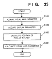
- Fig. 33 is a flow chart showing the processing of the line of sight parameter calculation unit 2610 in the image processing apparatus of the fifth embodiment.
- viewpoint parameters are acquired from the viewpoint parameter calculation unit 2607.
- the viewpoint parameters include the viewpoint position 2624 of the user shown in Fig. 32.
- display parameters are acquired from the display parameter holding unit 2604.
- the display parameters are expressed by the end point 2621 of the display screen 2601, and the display screen vector 2622.
- the display screen vector 2622 is determined by the inclination, actual size, and pixel size of the display screen 2601.
- step S334 line of sight parameters corresponding to the direction of the pixel position 2623 viewed from the viewpoint position 2624 of the user are calculated.
- Fig. 34 shows the calculation principle of the virtual viewpoint parameter calculation unit 2611 and the pixel position calculation unit 2612 in the image processing apparatus of the fifth embodiment.
- reference numeral 2641 denotes a straight line including the viewpoint array upon photographing of multi-viewpoint images stored in the image database 2603; 2642, a virtual viewpoint as the intersecting point between the line of sight 2625 and the straight line 2641; 2643, a viewpoint array vector representing the inclination of the straight line 2641; and 2644, an end point of the straight line 2641.
- Reference numeral 2645 denotes a view field with a field angle ⁇ at the virtual viewpoint 2642; 2646, a focal point vector having a length matching the focal length of the camera which photographs the multi-viewpoint images, and an inclination matching that of the camera; 2647, a virtual imaging plane at the virtual viewpoint 2642; 2648, a pixel position as the intersecting point between the virtual imaging plane 2647 and the line of sight 2625; and 2649, an imaging plane vector which has a length matching the pixel pitch of the virtual imaging plane 2647 and an inclination matching that of the virtual imaging plane 2647 (normally, perpendicular to the focal point vector 2646).
- the virtual viewpoint 2642, the virtual point array vector 2643, the end point 2644, the focal point vector 2646, the pixel position 2648, and the imaging plane vector 2649 are respectively expressed by vectors X, T, X1, f, Xp', and p'.
- vector components in the up-and-down direction are ignored, and processing is performed in a plane defined by the right-and-left and back-and-forth directions.
- viewpoint array vector 2643 and the end point 2644 are held in the viewpoint array holding unit 2605 as values representing the straight line 2641.
- the focal point vector 2646 and the imaging plane vector 2649 are held in the image parameter holding unit 2606 as image parameters.
- the size of the imaging plane vector 2649 is equal to the cell size (the size of one pixel) of an actual imaging plane.
- the straight line 2641 is set to be parallel to the display screen vector 2622.
- the virtual viewpoint parameter calculation unit 2611 calculates the virtual viewpoint parameter t by solving formulas (14) and (15) to calculate the virtual viewpoint position vector X.
- the pixel position calculation unit 2612 calculates the pixel position parameter i' by solving formulas (16) and (17), and outputs the calculated parameter.
- the image database 2603 holds multi-viewpoint images photographed from viewpoints set at sufficiently fine intervals.
- an image photographed from a viewpoint closest to the virtual viewpoint 2642 is found from the image database 2603.
- the value of a pixel at a position closest to the position 2648 of the pixel of interest calculated by the pixel position calculation unit 2612 is acquired, and is output as the pixel value signal 2616.
- the processing of the distortion correction unit 3102 will be described in detail below. Since images stored in the image database 2603 are photographed by changing the viewpoint in the right-and-left direction, they have no parallax information in the up-and-down direction. For this reason, the image generation unit 2608 cannot optically perfectly re-construct an image corresponding to viewpoint movement in the back-and-forth direction, and the re-constructed image is distorted in the up-and-down direction.
- the distortion correction unit 3102 enlarges or reduced the image in the up-and-down direction in correspondence with the viewpoint position 2624 of the user, thereby correcting the distortion of an image of an object separated from the straight line 2641 by a specific distance.
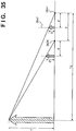
- Fig. 35 shows the principle of the distortion correction unit 3102.
- reference symbol T denotes the height of a given object
- Td the distance to the object
- F the focal length of the camera
- S the height of a photographed image of the object
- z the viewpoint moving distance in the back-and-forth direction
- S' the viewpoint moving distance in the back-and-forth direction
- the distortion correction unit 3102 sets, as the viewpoint moving distance z, a difference between the coordinate value, in the back-and-forth direction, of the viewpoint position 2624 of the user obtained from the viewpoint parameter calculation unit 2607, and the coordinate value, in the back-and-forth direction, of the straight line 2641 obtained from the viewpoint array holding unit 2605.
- the image parameter holding unit 2606 holds the value of a rough distance to the point of interest (or the in-focus point) of the photographed object as the distance Td.
- the distortion correction unit 3102 acquires this value from the image parameter holding unit 2606.
- the distortion correction unit 3102 calculates the degree of distortion by solving formula (20), and enlarges or reduces the image received from the image generation unit 2608 by a factor of the degree of distortion.
- the distortion correction unit 3102 outputs the corrected image to the image display unit 2614.
- the image processing apparatus of this embodiment can display an image corresponding to the viewpoint position even when the viewpoint position of an observer moves not only in a direction parallel to the straight line including the viewpoint array but also in the back-and-forth direction.
- the viewpoint parameter calculation unit 2607 calculates viewpoint parameters corresponding to the positions of the right and left eyes
- the image generation unit 2608 generates images presented for the right and left eyes
- a binocular stereoscopic display apparatus which can move the viewpoint in the back-and-forth and right-and-left directions can be realized.
- An image display apparatus which can freely display images corresponding to line of sight movement even when the viewpoint interval of images held in the image database 2603 is not sufficiently fine will be explained below.
- Fig. 36 is a block diagram showing the arrangement of an image processing apparatus of this embodiment.
- the same reference numerals in Fig. 36 denote the same parts as in the fifth embodiment, and a detailed description thereof will be omitted.
- an interpolation processing unit 2617 is arranged between the image database 2603 and the pixel value calculation unit 2613.
- the interpolation processing unit 2617 generates a group of images with sufficiently fine viewpoint intervals by executing interpolation processing using images which are photographed from viewpoints set at coarse intervals and stored in the image data base 2603. Using the interpolated images with sufficiently fine viewpoint intervals, an image corresponding to a change in viewpoint of a user can be generated as in the fifth embodiment.
- the image database 2603 holds images from photographing viewpoints aligned on a straight line in the right-and-left direction.
- the interpolation processing unit 2617 will be described in detail below with reference to Figs. 37 to 42.
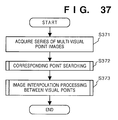
- Fig. 37 is a flow chart showing the flow of the processing of the interpolation processing unit 2617 of this embodiment.
- step S371 a group of images photographed at coarse viewpoint intervals are acquired from the image database 2603.
- step S372 corresponding point searching (motion vector detection) processing among images is performed.
- the flow advances to step S373 to perform interpolation processing of images between viewpoints, thus obtaining multi-viewpoint images with sufficiently fine viewpoint intervals.
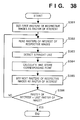
- Fig. 38 is a flow chart showing the corresponding point searching processing in step S372.
- step S381 the first raster of each image is initially set to be the raster of interest.
- step S382 the rasters of interest of the respective images are read out onto a work memory to virtually constitute a j-th epipolar plane.
- step S383 straight lines on which corresponding points are present are extracted.
- step S384 the corresponding points are calculated from the extracted straight lines, and the calculated points are stored. The above-mentioned processing is repeated for all the rasters in steps S385 and S386.
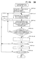
- Fig. 39 shows the detailed algorithm of the corresponding point detection on the j-th EPI.
- TH2 is a threshold value for finding the corresponding points, and is set in correspondence with an allowable error amount between corresponding pixels.
- k1 is a value determined by the camera interval and the distance to an object, and is set to be 20 (i.e., assume that a movement exceeding 20 pixels is not made) in this embodiment.
- nx is the number of pixels, in the main scanning direction, of an image. If EPj(x + m x (i-r),i) is not present, it is determined that no corresponding point for this m is present, and the processing is continued.
- a corresponding point with priority level 1 is obtained from the straight line with the inclination m obtained in steps A1 and A2, and is stored in the memory. If a plurality of corresponding points are obtained, all the points are stored as corresponding points of priority level 1 for the sake of simplicity. Pixels obtained as the corresponding points are set to be processed pixels.
- step A1 The value j is incremented by one, and the flow returns to step A1. More specifically, processing starting from step A1 is repeated for the next raster line.
- step S373 Upon completion of the processing in step S372, the flow advances to step S373 to perform image interpolation processing.
- the image interpolation processing is performed using the corresponding points calculated in step S372.
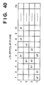
- the detailed algorithm will be described below while taking Fig. 40 as an example.
- Fig. 40 shows the j-th epipolar plane.
- a1 and b1 represent the corresponding points of priority level 1
- c2 represents corresponding points of priority level 2.
- n images are interpolated at equal intervals between input images.
- n 2.
- two lines are interpolated between each two adjacent lines of the epipolar plane, and the pixel values of the interpolated lines, which are present on straight lines connecting the corresponding points on the original epipolar plane, can be set to be an average value of the corresponding points.
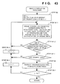
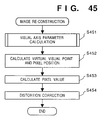
- the algorithm is as shown in Fig. 43.
- a straight line connecting the corresponding points of the priority level 1 on the j-th EPI is assumed, and the pixel values of interpolated lines, which are present on this straight line, are set to be an average value of pixel values on the original images present on the straight line.
- the pixel value of point a on the straight line connecting the corresponding point is set to be an average value of the pixel value of the point a1.
- the point is interpolated based on a line having the most moderate slope.
- processing for corresponding points with priority level 2 is performed.
- This processing is basically the same as that in step B1.
- pixels which have already been interpolated in step B1 are not processed.
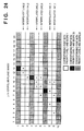
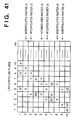
- This processing will be described below with reference to Fig. 41.
- Pixels (3, 8) and (2, 9) are normally interpolated by the corresponding points c2.
- no processing is performed for pixels (3, 8) and (2, 9). Therefore, pixels interpolated by the corresponding points b2 are four pixels (5, 2), (4, 3), (4, 5), and (3, 6). In the example shown in Fig. 41, occlusion occurs on this portion.
- the above processing can solve the problem of occlusion.
- processing for corresponding points with priority level 3 is performed. As in step B2, already interpolated pixels are not processed. Similarly, processing is performed up to corresponding points with the last priority level.
- Pixels which are not interpolated after the processing in steps B1 to B3 are interpolated based on surrounding pixels.
- a method to be used in this case a method using an average value of surrounding pixels, a method of directly using the value of a pixel closest to the pixel of interest, and the like are available.
- interpolated images are obtained using j2, j3, j5, j6, j8, and j9.
- the lines interpolated by the above processing in steps B1 to B4 are represented by j2, j3, j5, j6, j8, and j9, as shown in Fig. 41.
- interpolated images are generated based on images in the image database 2603, as described above, an image from a viewpoint other than the photographing viewpoints on the straight line including the viewpoint array can be obtained. Thus, an image from an arbitrary viewpoint can be generated. Therefore, the image database 2603 need not store multi-viewpoint images with sufficiently fine viewpoint intervals, and the storage capacity of the image database 2603 can be greatly reduced.
- the image parameter holding unit 2606 in order to calculate the degree of distortion in the distortion correction unit 3102, the image parameter holding unit 2606 must hold the value of a rough distance to the point of interest (or the in-focus point) on the photographed object as the distance Td.
- This embodiment develops the image processing apparatus of the sixth embodiment, and an image processing apparatus which can automatically discriminate the value of the degree of distortion in the distortion correction unit 3102 will be explained.
- the arrangement of the image processing apparatus of this embodiment is substantially the same as that shown in Fig. 36.
- the distortion correction unit 3102 automatically discriminates the degree of distortion in cooperation with the interpolation processing unit 2617.
- the interpolation correction unit 2617 supplies, to the distortion correction unit 3102, the inclination m of the straight line extracted in the straight line detection processing (step S783 in Fig. 38) in the corresponding point searching processing (step S372 in Fig. 37).
- W the width (in units of pixels) of an image
- ⁇ the field angle of the camera, which are held in the image parameter holding unit 2606.
- A is the viewpoint interval of images stored in the image database 2603, which interval is held in the viewpoint array holding unit 2605.
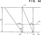
- Formula (21) is apparent from Fig. 44.
- a case will be examined below wherein a single object 131 is viewed from two viewpoints 133 and 134 on a viewpoint array straight line 132, which are separated by the distance A.
- the distance between the camera and object need not be detected in advance, thus providing an effect unique to this embodiment.
- a method of performing the above-mentioned calculation after an average value of inclinations m is calculated, a method of performing the calculation after an image is weighted in units of regions to estimate an object as the center, and the like are available in addition to the above-mentioned method.
- multi-viewpoint images which are photographed in advance are held in the image database 2603.
- the image database is replaced by a multi-eye television camera which can fetch multi-viewpoint images in real time, a arbitrary viewpoint image real-time photographing/display system can be realized.
- the present invention may be applied to a stand-alone type image processing apparatus, a system such as a multi-viewpoint television system, a multi-viewpoint video telephone terminal, a multi-viewpoint video meeting system, and the like, or a composite apparatus as a combination of a computer and another image processing apparatus.
- the image processing apparatus of each of the above embodiments detects the position of the eye of an observer and re-constructs an image viewed from the observer on the basis of a plurality of images, it can smoothly output an image corresponding to not only right-and-left movement but also back-and-forth movement of the viewpoint of the observer.
- multi-viewpoint image data including a plurality of images with different viewpoint positions
- a large number of images obtained from at least one camera, and a large number of images stored in a database can be used.
- the multi-viewpoint image data preferably include images whose photographing positions are changed at sufficiently fine intervals.
- an image having a desired position between two adjacent photographing positions as a viewpoint position can be generated by interpolating photographed images, and an image can be re-constructed using the photographed images and generated images as multi-viewpoint image data.
- an image is re-constructed in such a manner that parameters required for re-constructing an image are calculated on the basis of the eye position of an observer and the type of an image output apparatus, corresponding pixels between an image to be reconstructed and multi-viewpoint images are calculated on the basis of the calculated parameters, and the corresponding pixels are extracted from the multi-viewpoint images.
- corresponding pixels can be calculated, and hence, an image can be reconstructed satisfactorily.
- a stereoscopic display, a lenticular display, and the like can be used in addition to a normal display.
- the image processing method and apparatus can provide an effect of displaying an image in correspondence with movement of the eye position of an observer in directions including the back-and-forth direction.
Applications Claiming Priority (9)
| Application Number | Priority Date | Filing Date | Title |
|---|---|---|---|
| JP107855/94 | 1994-04-22 | ||
| JP10785594 | 1994-04-22 | ||
| JP10785394 | 1994-04-22 | ||
| JP10785494A JPH07296194A (ja) | 1994-04-22 | 1994-04-22 | 画像処理方法およびその装置 |
| JP6107855A JP3054312B2 (ja) | 1994-04-22 | 1994-04-22 | 画像処理装置及び方法 |
| JP6107853A JPH07296193A (ja) | 1994-04-22 | 1994-04-22 | 画像処理方法およびその装置 |
| JP10785494 | 1994-04-22 | ||
| JP107853/94 | 1994-04-22 | ||
| JP107854/94 | 1994-04-22 |
Publications (3)
| Publication Number | Publication Date |
|---|---|
| EP0684585A2 true EP0684585A2 (de) | 1995-11-29 |
| EP0684585A3 EP0684585A3 (de) | 1996-04-17 |
| EP0684585B1 EP0684585B1 (de) | 2003-02-05 |
Family
ID=27311091
Family Applications (1)
| Application Number | Title | Priority Date | Filing Date |
|---|---|---|---|
| EP95302680A Expired - Lifetime EP0684585B1 (de) | 1994-04-22 | 1995-04-21 | Bilderzeugungsverfahren und -gerät |
Country Status (3)
| Country | Link |
|---|---|
| US (2) | US6263100B1 (de) |
| EP (1) | EP0684585B1 (de) |
| DE (1) | DE69529548T2 (de) |
Cited By (3)
| Publication number | Priority date | Publication date | Assignee | Title |
|---|---|---|---|---|
| EP0631250A2 (de) * | 1993-06-21 | 1994-12-28 | Nippon Telegraph And Telephone Corporation | Verfahren und Vorrichtung zur dreidimenzionalen Bilderzeugung eines Objektes |
| DE19549306A1 (de) * | 1995-12-22 | 1997-07-03 | Art & Com Medientechnologie Un | Verfahren und Vorrichtung zur bildlichen Darstellung raumbezogener Daten |
| EP1860612A2 (de) * | 2006-05-22 | 2007-11-28 | Canon Kabushiki Kaisha | Korrektur von Bildverzerrungen |
Families Citing this family (35)
| Publication number | Priority date | Publication date | Assignee | Title |
|---|---|---|---|---|
| JP4374625B2 (ja) * | 1998-05-08 | 2009-12-02 | ソニー株式会社 | 画像生成装置及び方法 |
| JP4310850B2 (ja) * | 1999-05-28 | 2009-08-12 | コニカミノルタホールディングス株式会社 | 3次元形状の対応付け方法 |
| JP3614324B2 (ja) * | 1999-08-31 | 2005-01-26 | シャープ株式会社 | 画像の補間システムおよび画像の補間方法 |
| US6583808B2 (en) | 2001-10-04 | 2003-06-24 | National Research Council Of Canada | Method and system for stereo videoconferencing |
| JP4148671B2 (ja) * | 2001-11-06 | 2008-09-10 | ソニー株式会社 | 表示画像制御処理装置、動画像情報送受信システム、および表示画像制御処理方法、動画像情報送受信方法、並びにコンピュータ・プログラム |
| JP3739693B2 (ja) * | 2001-11-09 | 2006-01-25 | 本田技研工業株式会社 | 画像認識装置 |
| JP3951695B2 (ja) * | 2001-12-11 | 2007-08-01 | ソニー株式会社 | 画像配信システムおよび方法、画像配信装置および方法、画像受信装置および方法、記録媒体、並びにプログラム |
| US7411594B2 (en) | 2002-01-15 | 2008-08-12 | Canon Kabushiki Kaisha | Information processing apparatus and method |
| JP4211292B2 (ja) * | 2002-06-03 | 2009-01-21 | ソニー株式会社 | 画像処理装置および画像処理方法、プログラム並びにプログラム記録媒体 |
| JP2005050037A (ja) * | 2003-07-31 | 2005-02-24 | Canon Inc | 画像処理方法および装置 |
| EP1792282B1 (de) * | 2004-08-30 | 2010-07-21 | Commonwealth Scientific And Industrial Research Organisation | Verfahren zur automatischen 3D-Bildgebung |
| US7660432B2 (en) * | 2004-10-21 | 2010-02-09 | Kazunari Era | Method for controlling creation of stereoscopic image |
| JP4508049B2 (ja) * | 2005-09-05 | 2010-07-21 | 株式会社日立製作所 | 360°画像撮影装置 |
| US8014588B2 (en) * | 2005-11-04 | 2011-09-06 | Cognitech, Inc. | System and method for three-dimensional estimation based on image data |
| US7865031B2 (en) * | 2006-04-18 | 2011-01-04 | Tandent Vision Science, Inc. | Method and system for automatic correction of chromatic aberration |
| JP5020573B2 (ja) * | 2006-09-01 | 2012-09-05 | キヤノン株式会社 | 画像処理装置およびその方法 |
| WO2008087632A2 (en) * | 2007-01-15 | 2008-07-24 | Humaneyes Technologies Ltd. | A method and a system for lenticular printing |
| US8520060B2 (en) | 2007-02-25 | 2013-08-27 | Humaneyes Technologies Ltd. | Method and a system for calibrating and/or visualizing a multi image display and for reducing ghosting artifacts |
| KR101397124B1 (ko) * | 2007-02-28 | 2014-05-19 | 주성엔지니어링(주) | 기판지지프레임 및 이를 포함하는 기판처리장치, 이를이용한 기판의 로딩 및 언로딩 방법 |
| JP4720785B2 (ja) * | 2007-05-21 | 2011-07-13 | 富士フイルム株式会社 | 撮像装置、画像再生装置、撮像方法及びプログラム |
| US9035968B2 (en) * | 2007-07-23 | 2015-05-19 | Humaneyes Technologies Ltd. | Multi view displays and methods for producing the same |
| US8086026B2 (en) * | 2008-06-27 | 2011-12-27 | Waldean Schulz | Method and system for the determination of object positions in a volume |
| EP2261827B1 (de) * | 2009-06-10 | 2015-04-08 | Dassault Systèmes | Verfahren, Programm und Vorrichtung zur Anzeige einer Anordnung von Objekten auf einer PLM-Datenbank |
| US8947448B2 (en) * | 2009-12-24 | 2015-02-03 | Sony Corporation | Image processing device, image data generation device, image processing method, image data generation method, and data structure of image file |
| JP5409481B2 (ja) * | 2010-03-29 | 2014-02-05 | 富士フイルム株式会社 | 複眼撮影装置及びプログラム |
| SG176327A1 (en) | 2010-05-20 | 2011-12-29 | Sony Corp | A system and method of image processing |
| KR101841750B1 (ko) * | 2011-10-11 | 2018-03-26 | 한국전자통신연구원 | 매칭 정보에 의한 입체 영상 보정 장치 및 그 방법 |
| JP6282145B2 (ja) | 2014-03-13 | 2018-02-21 | キヤノン株式会社 | 装置、画像処理装置、方法及びプログラム |
| JP6395423B2 (ja) * | 2014-04-04 | 2018-09-26 | キヤノン株式会社 | 画像処理装置、制御方法及びプログラム |
| DE102016203392B3 (de) | 2016-03-02 | 2017-06-22 | Heidelberger Druckmaschinen Ag | Bildinspektionsverfahren mit mehreren Kameras |
| KR102534875B1 (ko) * | 2016-12-08 | 2023-05-22 | 한국전자통신연구원 | 카메라 어레이와 다중 초점 영상을 이용하여 임의 시점의 영상을 생성하는 방법 및 장치 |
| JP6824579B2 (ja) * | 2017-02-17 | 2021-02-03 | 株式会社ソニー・インタラクティブエンタテインメント | 画像生成装置および画像生成方法 |
| JP6982978B2 (ja) | 2017-04-26 | 2021-12-17 | キヤノン株式会社 | 情報処理装置、情報処理方法、およびプログラム |
| JP2019036821A (ja) | 2017-08-14 | 2019-03-07 | キヤノン株式会社 | 画像処理装置、画像処理方法、及びプログラム |
| JP7123736B2 (ja) * | 2018-10-23 | 2022-08-23 | キヤノン株式会社 | 画像処理装置、画像処理方法、およびプログラム |
Citations (1)
| Publication number | Priority date | Publication date | Assignee | Title |
|---|---|---|---|---|
| GB2244621A (en) * | 1990-05-29 | 1991-12-04 | Europ Vision Systems Centre Lt | Machine vision stereo matching |
Family Cites Families (11)
| Publication number | Priority date | Publication date | Assignee | Title |
|---|---|---|---|---|
| US4825393A (en) * | 1986-04-23 | 1989-04-25 | Hitachi, Ltd. | Position measuring method |
| JP2917155B2 (ja) * | 1989-12-18 | 1999-07-12 | 株式会社日立製作所 | 画像結合装置及び方法 |
| AU652051B2 (en) * | 1991-06-27 | 1994-08-11 | Eastman Kodak Company | Electronically interpolated integral photography system |
| US5473441A (en) * | 1992-06-12 | 1995-12-05 | Fuji Photo Film Co., Ltd. | Video signal reproduction processing method and apparatus for reproduction of a recorded video signal as either a sharp still image or a clear moving image |
| JP3058774B2 (ja) * | 1993-01-29 | 2000-07-04 | 株式会社河合楽器製作所 | 映像合成装置及び映像合成方法 |
| JPH0719832A (ja) * | 1993-06-21 | 1995-01-20 | Canon Inc | 複数画像の対応点抽出方法 |
| DE69434685T2 (de) * | 1993-08-04 | 2006-09-14 | Canon K.K. | Bildverarbeitungsverfahren und -gerät |
| US5764871A (en) * | 1993-10-21 | 1998-06-09 | Eastman Kodak Company | Method and apparatus for constructing intermediate images for a depth image from stereo images using velocity vector fields |
| US5768404A (en) * | 1994-04-13 | 1998-06-16 | Matsushita Electric Industrial Co., Ltd. | Motion and disparity estimation method, image synthesis method, and apparatus for implementing same methods |
| JPH08115439A (ja) * | 1994-10-13 | 1996-05-07 | Canon Inc | 画像データ処理装置及び画像再生装置 |
| US5703961A (en) * | 1994-12-29 | 1997-12-30 | Worldscape L.L.C. | Image transformation and synthesis methods |
-
1995
- 1995-04-21 DE DE69529548T patent/DE69529548T2/de not_active Expired - Lifetime
- 1995-04-21 EP EP95302680A patent/EP0684585B1/de not_active Expired - Lifetime
-
1997
- 1997-04-16 US US08/838,177 patent/US6263100B1/en not_active Expired - Lifetime
-
2001
- 2001-05-30 US US09/866,669 patent/US6628820B2/en not_active Expired - Lifetime
Patent Citations (1)
| Publication number | Priority date | Publication date | Assignee | Title |
|---|---|---|---|---|
| GB2244621A (en) * | 1990-05-29 | 1991-12-04 | Europ Vision Systems Centre Lt | Machine vision stereo matching |
Non-Patent Citations (1)
| Title |
|---|
| SYSTEMS & COMPUTERS IN JAPAN, vol. 17, no. 2, February 1986 NEW YORK US, pages 89-96, AGUI E.A. 'AN IN-BETWEENING METHOD OF GRAY-VALUED IMAGES USING DENSITY CONTOUR LINES' * |
Cited By (9)
| Publication number | Priority date | Publication date | Assignee | Title |
|---|---|---|---|---|
| EP0631250A2 (de) * | 1993-06-21 | 1994-12-28 | Nippon Telegraph And Telephone Corporation | Verfahren und Vorrichtung zur dreidimenzionalen Bilderzeugung eines Objektes |
| EP0631250B1 (de) * | 1993-06-21 | 2002-03-20 | Nippon Telegraph And Telephone Corporation | Verfahren und Vorrichtung zur dreidimensionalen Bilderzeugung von Objekten |
| DE19549306A1 (de) * | 1995-12-22 | 1997-07-03 | Art & Com Medientechnologie Un | Verfahren und Vorrichtung zur bildlichen Darstellung raumbezogener Daten |
| US6100897A (en) * | 1995-12-22 | 2000-08-08 | Art +Com Medientechnologie Und Gestaltung Gmbh | Method and device for pictorial representation of space-related data |
| USRE41428E1 (en) * | 1995-12-22 | 2010-07-13 | Art + Com Ag | Method and device for pictorial representation of space-related data |
| USRE44550E1 (en) * | 1995-12-22 | 2013-10-22 | ART + COM Innovationpool GmbH | Method and device for pictorial representation of space-related data |
| EP1860612A2 (de) * | 2006-05-22 | 2007-11-28 | Canon Kabushiki Kaisha | Korrektur von Bildverzerrungen |
| EP1860612A3 (de) * | 2006-05-22 | 2011-08-31 | Canon Kabushiki Kaisha | Korrektur von Bildverzerrungen |
| US8953057B2 (en) | 2006-05-22 | 2015-02-10 | Canon Kabushiki Kaisha | Display apparatus with image-capturing function, image processing apparatus, image processing method, and image display system |
Also Published As
| Publication number | Publication date |
|---|---|
| US6263100B1 (en) | 2001-07-17 |
| DE69529548D1 (de) | 2003-03-13 |
| DE69529548T2 (de) | 2003-11-27 |
| EP0684585B1 (de) | 2003-02-05 |
| US6628820B2 (en) | 2003-09-30 |
| US20010043739A1 (en) | 2001-11-22 |
| EP0684585A3 (de) | 1996-04-17 |
Similar Documents
| Publication | Publication Date | Title |
|---|---|---|
| EP0684585B1 (de) | Bilderzeugungsverfahren und -gerät | |
| US6608622B1 (en) | Multi-viewpoint image processing method and apparatus | |
| EP0680019B1 (de) | Bildverarbeitungsverfahren und -gerät | |
| JP4065488B2 (ja) | 3次元画像生成装置、3次元画像生成方法及び記憶媒体 | |
| US6191808B1 (en) | Image processing method with viewpoint compensation and apparatus therefor | |
| EP0680014B1 (de) | Verfahren und Vorrichtung zur Bildverarbeitung | |
| JP3728160B2 (ja) | 奥行き画像計測装置及び方法、並びに複合現実感提示システム | |
| EP1303839B1 (de) | System und verfahren zur median-fusion von tiefenplänen | |
| US20070248260A1 (en) | Supporting a 3D presentation | |
| JP3524147B2 (ja) | 3次元画像表示装置 | |
| KR100897542B1 (ko) | 임의 시점 영상 합성 시 영상 보정 방법 및 장치 | |
| JP2006115198A (ja) | 立体画像生成プログラム、立体画像生成システムおよび立体画像生成方法 | |
| JP2008217243A (ja) | 画像生成装置 | |
| JP3032414B2 (ja) | 画像処理方法および画像処理装置 | |
| US10148931B2 (en) | Three-dimensional video image display processing device, video information recording medium, video information providing server, and recording medium storing a program | |
| JPH08147497A (ja) | 画像処理方法及びその装置 | |
| JPH07296195A (ja) | 画像処理装置及び方法 | |
| KR20130039173A (ko) | 매칭 정보에 의한 입체 영상 보정 장치 및 그 방법 | |
| CN109963143A (zh) | 一种ar眼镜的图像获取方法及系统 | |
| KR100927234B1 (ko) | 깊이 정보 생성 방법, 그 장치 및 그 방법을 실행하는프로그램이 기록된 기록매체 | |
| JPH0749944A (ja) | 画像処理方法およびその装置 | |
| JPH09288735A (ja) | 画像処理装置 | |
| JP2795784B2 (ja) | 複数視点3次元画像入力装置 | |
| JP2002159021A (ja) | 目盛表示装置及びその方法 | |
| JPH07296194A (ja) | 画像処理方法およびその装置 |
Legal Events
| Date | Code | Title | Description |
|---|---|---|---|
| PUAI | Public reference made under article 153(3) epc to a published international application that has entered the european phase |
Free format text: ORIGINAL CODE: 0009012 |
|
| AK | Designated contracting states |
Kind code of ref document: A2 Designated state(s): DE FR GB IT NL |
|
| PUAL | Search report despatched |
Free format text: ORIGINAL CODE: 0009013 |
|
| AK | Designated contracting states |
Kind code of ref document: A3 Designated state(s): DE FR GB IT NL |
|
| 17P | Request for examination filed |
Effective date: 19960829 |
|
| 17Q | First examination report despatched |
Effective date: 19980930 |
|
| GRAG | Despatch of communication of intention to grant |
Free format text: ORIGINAL CODE: EPIDOS AGRA |
|
| GRAG | Despatch of communication of intention to grant |
Free format text: ORIGINAL CODE: EPIDOS AGRA |
|
| GRAG | Despatch of communication of intention to grant |
Free format text: ORIGINAL CODE: EPIDOS AGRA |
|
| GRAH | Despatch of communication of intention to grant a patent |
Free format text: ORIGINAL CODE: EPIDOS IGRA |
|
| GRAH | Despatch of communication of intention to grant a patent |
Free format text: ORIGINAL CODE: EPIDOS IGRA |
|
| GRAA | (expected) grant |
Free format text: ORIGINAL CODE: 0009210 |
|
| AK | Designated contracting states |
Designated state(s): DE FR GB IT NL |
|
| PG25 | Lapsed in a contracting state [announced via postgrant information from national office to epo] |
Ref country code: NL Free format text: LAPSE BECAUSE OF FAILURE TO SUBMIT A TRANSLATION OF THE DESCRIPTION OR TO PAY THE FEE WITHIN THE PRESCRIBED TIME-LIMIT Effective date: 20030205 Ref country code: IT Free format text: LAPSE BECAUSE OF FAILURE TO SUBMIT A TRANSLATION OF THE DESCRIPTION OR TO PAY THE FEE WITHIN THE PRE;WARNING: LAPSES OF ITALIAN PATENTS WITH EFFECTIVE DATE BEFORE 2007 MAY HAVE OCCURRED AT ANY TIME BEFORE 2007. THE CORRECT EFFECTIVE DATE MAY BE DIFFERENT FROM THE ONE RECORDED.SCRIBED TIME-LIMIT Effective date: 20030205 |
|
| REG | Reference to a national code |
Ref country code: GB Ref legal event code: FG4D |
|
| REF | Corresponds to: |
Ref document number: 69529548 Country of ref document: DE Date of ref document: 20030313 Kind code of ref document: P |
|
| NLV1 | Nl: lapsed or annulled due to failure to fulfill the requirements of art. 29p and 29m of the patents act | ||
| ET | Fr: translation filed | ||
| PLBE | No opposition filed within time limit |
Free format text: ORIGINAL CODE: 0009261 |
|
| STAA | Information on the status of an ep patent application or granted ep patent |
Free format text: STATUS: NO OPPOSITION FILED WITHIN TIME LIMIT |
|
| 26N | No opposition filed |
Effective date: 20031106 |
|
| PGFP | Annual fee paid to national office [announced via postgrant information from national office to epo] |
Ref country code: DE Payment date: 20130430 Year of fee payment: 19 Ref country code: GB Payment date: 20130418 Year of fee payment: 19 |
|
| PGFP | Annual fee paid to national office [announced via postgrant information from national office to epo] |
Ref country code: FR Payment date: 20130517 Year of fee payment: 19 |
|
| REG | Reference to a national code |
Ref country code: DE Ref legal event code: R119 Ref document number: 69529548 Country of ref document: DE |
|
| GBPC | Gb: european patent ceased through non-payment of renewal fee |
Effective date: 20140421 |
|
| REG | Reference to a national code |
Ref country code: FR Ref legal event code: ST Effective date: 20141231 |
|
| REG | Reference to a national code |
Ref country code: DE Ref legal event code: R119 Ref document number: 69529548 Country of ref document: DE Effective date: 20141101 |
|
| PG25 | Lapsed in a contracting state [announced via postgrant information from national office to epo] |
Ref country code: DE Free format text: LAPSE BECAUSE OF NON-PAYMENT OF DUE FEES Effective date: 20141101 Ref country code: GB Free format text: LAPSE BECAUSE OF NON-PAYMENT OF DUE FEES Effective date: 20140421 |
|
| PG25 | Lapsed in a contracting state [announced via postgrant information from national office to epo] |
Ref country code: FR Free format text: LAPSE BECAUSE OF NON-PAYMENT OF DUE FEES Effective date: 20140430 |