EP0683093A1 - Détecteur de force de pédalage pour bicyclette assistée à moteur - Google Patents
Détecteur de force de pédalage pour bicyclette assistée à moteur Download PDFInfo
- Publication number
- EP0683093A1 EP0683093A1 EP95106200A EP95106200A EP0683093A1 EP 0683093 A1 EP0683093 A1 EP 0683093A1 EP 95106200 A EP95106200 A EP 95106200A EP 95106200 A EP95106200 A EP 95106200A EP 0683093 A1 EP0683093 A1 EP 0683093A1
- Authority
- EP
- European Patent Office
- Prior art keywords
- crank axle
- pedaling force
- crank
- torsion bar
- motor
- Prior art date
- Legal status (The legal status is an assumption and is not a legal conclusion. Google has not performed a legal analysis and makes no representation as to the accuracy of the status listed.)
- Granted
Links
Images


Classifications
-
- B—PERFORMING OPERATIONS; TRANSPORTING
- B62—LAND VEHICLES FOR TRAVELLING OTHERWISE THAN ON RAILS
- B62M—RIDER PROPULSION OF WHEELED VEHICLES OR SLEDGES; POWERED PROPULSION OF SLEDGES OR SINGLE-TRACK CYCLES; TRANSMISSIONS SPECIALLY ADAPTED FOR SUCH VEHICLES
- B62M3/00—Construction of cranks operated by hand or foot
- B62M3/003—Combination of crank axles and bearings housed in the bottom bracket
-
- B—PERFORMING OPERATIONS; TRANSPORTING
- B62—LAND VEHICLES FOR TRAVELLING OTHERWISE THAN ON RAILS
- B62M—RIDER PROPULSION OF WHEELED VEHICLES OR SLEDGES; POWERED PROPULSION OF SLEDGES OR SINGLE-TRACK CYCLES; TRANSMISSIONS SPECIALLY ADAPTED FOR SUCH VEHICLES
- B62M6/00—Rider propulsion of wheeled vehicles with additional source of power, e.g. combustion engine or electric motor
- B62M6/40—Rider propelled cycles with auxiliary electric motor
- B62M6/45—Control or actuating devices therefor
- B62M6/50—Control or actuating devices therefor characterised by detectors or sensors, or arrangement thereof
-
- B—PERFORMING OPERATIONS; TRANSPORTING
- B62—LAND VEHICLES FOR TRAVELLING OTHERWISE THAN ON RAILS
- B62M—RIDER PROPULSION OF WHEELED VEHICLES OR SLEDGES; POWERED PROPULSION OF SLEDGES OR SINGLE-TRACK CYCLES; TRANSMISSIONS SPECIALLY ADAPTED FOR SUCH VEHICLES
- B62M6/00—Rider propulsion of wheeled vehicles with additional source of power, e.g. combustion engine or electric motor
- B62M6/40—Rider propelled cycles with auxiliary electric motor
- B62M6/55—Rider propelled cycles with auxiliary electric motor power-driven at crank shafts parts
Definitions
- the present invention relates to a pedaling force detector for a motor-assisted bicycle having a power transmission system for transmitting a pedaling force applied to crank pedals to a wheel, incorporating an assistive motor, and the output of the assistive motor is controlled on the basis of the pedaling force detected by a pedaling force detecting means.
- Pedaling force detectors for such a motor-assisted bicycle are disclosed in Japanese Patent Laid-open (Kokai) Nos. 5-38379, 4-100790 and 4-244496.
- the pedaling force detector disclosed in Japanese Patent Laid-open (Kokai) No. 5-58379 detects a pedaling force applied to the crank pedals on the basis of the reaction of the sun of a planetary gear train. Since this known pedaling force detector has a complex, heavyweight construction and the planetary gear train must be driven by rider's power when the assistive motor is not used, the pedaling force detector causes a large loss of mechanical energy.
- the pedaling force detector disclosed in Japanese Patent Laid-open (Kokai) No. 4-100790 detects the pedaling force on the basis of the angle of torsion of a drive shaft connecting the crank axle to the rear wheel, and this pedaling force detector cannot be applied to general chain-drive bicycles.
- the pedaling force detector disclosed in Japanese Patent Laid-open (Kokai) No. 4-244496 detects the pedaling force on the basis of the tension of the chain connecting the crank axle and the rear wheel.
- This a pedaling force detected by this pedaling force detector includes errors attributable to the elongation of the chain due to stress induced in the chain during extended period of use and to an inappropriate initial tension of the chain.
- the present invention has been made in view of the foregoing problems and it is therefore an object of the present invention to provide a pedaling force detector for a motor-assisted bicycle, having a compact, lightweight construction, and capable of reducing loss of mechanical energy and of accurately detecting the pedaling force.
- a pedaling force detector for a motor-assisted bicycle comprises the pedaling force detecting means comprising: a torsion bar disposed within and coaxially with a crank axle driven for rotation by operating the crank pedals, having a first end connected to the crank axle and a second end connected to the assistive motor and the wheel; a converting means for converting the angle of torsion of the torsion bar into a corresponding axial displacement of the crank axle; and a displacement sensor for detecting the axial displacement.
- the converting means stated in claim 1 comprises: a driving member fitly put on the crank axle so as to be rotatable relative to the crank axle and to be restrained from axial sliding, and connected to the second end of the torsion bar; and a driven member fitly put on the crank axle so as to be axially slidable and to be restrained from rotation relative to the crank axle, and interlocked with the driving member by a cam mechanism; and the driven member moves axially on the crank axle according to the torsion of the torsion bar.
- the converting means stated in claim 1 comprises: a driving means fitly put on the crank axle so as to be rotatable relative to the crank axle and to be restrained from axial sliding, and connected to the second end of the torsion bar; an arm holder fitly put on the crank axle so as to be restrained from rotation and axial sliding relative to the crank axle; and arm members having driving arms pivotally supported at their middle parts on the arm holder, extended axially of the crank axle and in engagement with the driving member, and driven arms extended radially of the crank axle; and the driven arms are displaced axially of the crank axle according to the torsion of the torsion bar.
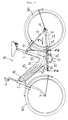
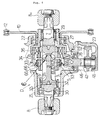
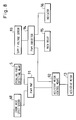
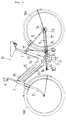
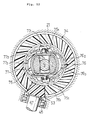
- Figs. 1 to 8 illustrates a first embodiment of the present invention, in which Fig. 1 is a general side view of a bicycle, Fig. 2 is an enlarged sectional view taken on line 2-2 in Fig. 1, Fig. 3 is a sectional view taken on line 3-3 in Fig. 2, Fig. 4 is a sectional view taken on line 4-4 in Fig. 3, Fig. 5 is an enlarged sectional view taken on line 5-5 in Fig. 2, Fig. 6 is an enlarged view of a portion indicated at 6 in Fig. 4, Fig. 7 is a diagrammatic view taken along the direction of the arrow 7 in Fig. 1, and Fig. 8 is a block diagram of a control system.
- a bicycle B has a main frame 1 having a V-shape in a side view, a front fork 3 is supported for turning on a head pipe 2 attached to the front end of the main frame 1, a handlebar 4 is attached to the upper end of the front fork 3, and a front wheel Wf is supported on the lower end of the front fork 3.
- a rear fork 6 extended backward from a part of the main frame 1 near the lower end of the main frame 1 is held rigidly in position by stays 5, and a rear wheel Wr is supported on the rear fork 6.
- a crank axle 7 is supported for rotation on the lower end of the main frame 1, a pair of crank arms 8 R and 8 L are mounted on the crank axle 7, and crank pedals 9 R and 9 L are attached to the free ends of the crank arms 8 R and 8 L respectively.
- a chain 12 is extended between a driving sprocket 10 driven for rotation by the crank axle 7 and a driven sprocket 11 mounted on the axle of the rear wheel Wr.
- An assistive motor 13 connected to the driving sprocket 10 disposed in the lower part of the main frame 1 generates an assistive driving force for assisting a pedaling force applied to the crank pedals 9 R and 9 L .
- a battery 15 comprising a plurality of Ni-Cd cells, i.e., a power supply for supplying power to drive the assistive motor 13, is contained in a battery box 14 disposed in the front part of the main frame 1.
- a main switch 16 is attached to the front wall of the battery box 14.
- a controller 17 comprising an electronic control unit for controlling the assistive motor 13, and a motor driver is disposed in the rear part of the main frame 1.
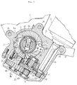
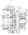
- a driving mechanism D included in the bicycle B will be described in detail hereinafter with reference to Figs. 2 to 7.
- a gear housing containing the driving mechanism D comprises a left housing member 21, i.e., a main housing member, a right housing member 22 attached to the right open end of the left housing member 21, and a lower housing member 23 joined to the lower surface of the left housing member 21.
- the left housing member 21 is fastened at its front upper part to the lower end of the main frame 1 with two bolts 24, and both the respective rear parts of the left housing member 21 and the right housing member 22 are fastened to the front end of the rear fork 6 with a single bolt 25.
- the lower housing member 23 is fastened to the lower surface of the left housing member 21 with a plurality of bolts 26 (only one of the bolts 26 is shown in Fig. 3).
- crank axle 7 The right end of the crank axle 7 is supported in a roller bearing 29 fitted in a sleeve 28 supported in a ball bearing 27 on the right housing member 22, and the left end of the crank axle 7 is supported in a ball bearing 30 on the left housing member 21.
- the crank axle 7 is provided in its middle part with an axially elongate through hole 71 diametrically extending through the crank axle 7.
- a torsion bar 31 is placed in the through hole 71 coaxially with the crank axle 7.
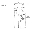
- An expanded head 311 formed at the left end (input end) of the torsion bar 31 is connected to the crank axle 7 with a collar 32, and an expanded head 312 formed at the right end (output end) of the torsion bar 31 is press-fitted in a groove formed in the inner circumference of an annular driving member 33 as shown in Fig. 4. As best shown in Fig.
- the opposite side surfaces of the through hole 71 of the crank axle 7 are curved substantially in the shape of a circular arc to enable the head 312 on the free end of the torsion bar 31 to turn through a predetermined angle relative to the head 311 on the fixed end, and to prevent the breakage of the torsion bar 31 by limiting a maximum angle of torsion of the torsion bar 31 when an excessively large load acts on the torsion bar 31.
- a first overrunning clutch 35 is disposed between a bevel gear 34 fixed to the inner circumference of the sleeve 28 and the driving member 33.
- the first overrunning clutch 35 comprises four pawls 36 pivotally supported on the periphery of the driving member 33 and biased radially outward with springs, not shown, and a plurality of ratchet teeth 341 formed in the inner circumference of the bevel gear 34.
- the assistive motor 13 is held on the left housing member 21 so that the output shaft 131 thereof extends obliquely forward and downward, and the free end of the output shaft 131 is supported in a ball bearing 41 on the lower end of the left housing member 21.
- a first intermediate shaft 44 is supported in a pair of ball bearings 42 and 43 on the left housing member 21 and the lower housing member 23, and a second intermediate shaft 47 is supported in a pair of ball bearings 45 and 46 on the left housing member 21 and the lower housing member 23.
- a spur gear 48 fixed to the output shaft 131 of the assistive motor 13 is in engagement with a spur gear 50 mounted on a second overrunning clutch 49 coupled with the first intermediate shaft 44, a spur gear 51 fixed to the first intermediate shaft 44 is in engagement with a spur gear 52 fixed to the second intermediate shaft 47, and a bevel gear 53 fixed to the second intermediate shaft 47 is in engagement with the bevel gear 34 fixed to the sleeve 28.
- the torque of the output shaft 131 is transmitted through the four spur gears 48, 50, 51 and 52, the two bevel gears 53 and 34 and the sleeve 28 to the driving sprocket 10.
- the second overrunning clutch 49 allows the driving sprocket 10 to be rotated freely by working the crank pedals 9 R and 9 L relative to the output shaft 131 when the assistive motor 13 stops due to the exhaustion of the battery 15.
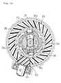
- a pedaling force detecting means S for detecting a pedaling force applied to the crank pedals 9 R and 9 L has an inner slider 61 fitly put on the crank axle 7 so as to be axially slidable and rotatable together with the crank axle 7.
- An outer slider 63 is supported on a plurality of balls 62 seated on the flange of the inner slider 61 for rotation relative to the inner slider 61.
- a pair of concave cam surfaces 331 are formed on a diameter in the end surface of the driving member 33 facing the inner slider 61, and a pair of convex cam surfaces 611 are formed in the end surface of the inner slider 61 so as to be in engagement with the concave cam surfaces 331.
- the driving member 33 and the inner slider 61 are the components of a converting means C in accordance with the present invention.
- a pivot bolt 64 and a stroke sensor 65 are disposed on the opposite sides, respectively, of the crank axle 7 on the left housing member 1.
- a sensor arm 66 has one end pivotally connected to the pivot bolt 64 and the other end in contact with the detecting rod 651 of the stroke sensor 65.
- the sensor arm 66 is provided in its middle part with an opening 661 (Fig. 2) through which the crank axle 7, the inner slider 61 and the outer slider 63 extend.
- a pair of projections 662 (Fig. 4) project radially inward from the edge of the opening 661.
- a spring 67 is compressed between the pair of projections 662 and the left housing member 21 to bias the sensor arm 66 to the right as viewed in Fig. 4.
- a crank axle speed sensor 68 is held on the left housing member 21 opposite to a toothed part 321 formed on the outer surface of the collar 32 coupling together the crank axle 7 and the head 311 of the torsion bar 31 to detect the rotating speed of the crank axle 7.
- crank arms 8 R and 8 L rotates the crank axle 7.
- the torque of the crank axle 7 is transmitted through the torsion bar 31, the driving member 33, the first overrunning clutch 35, the bevel gear 34, the sleeve 28, the driving sprocket 10, the chain 12 and the driven sprocket 11 to the rear wheel Wr.
- the pedaling force detecting means S detects a pedaling force applied to the crank pedals 9 R and 9 L .
- a torque corresponding to the pedaling force applied to the crank pedals 9 R and 9 L acts on the torsion bar 31 to twist the torsion bar 31 through a predetermined angle relative to the crank axle 7.
- the inner slider 61 mounted on the crank axle 7 so as to be axially slidable and restrained from turning relative to the crank axle 7 turns in the direction of the arrow a relative to the driving member 33 joined to the output end of the torsion bar 31 as shown in Fig. 6.
- the cam surfaces 611 of the inner slider 61 are pressed against the cam surfaces 331 of the driving member 33, the inner slider 61 is caused to slide in the direction of the arrow b on the crank axle 7 against the resilience of the spring 67, the outer slider 63 combined with the inner slider 61 pushes the sensor arm 66 at the projections 662 to turn the sensor arm 66 on the pivot bolt 64, and then the sensor arm 66 pushes the detecting rod 651 of the stroke sensor 65. Since the stroke of the detecting rod 651 of the stroke sensor 65 is proportional to the torsional angle of the torsion bar 31 corresponding to the pedaling force applied to the crank pedals 9 R and 9 L , the pedaling force is determined on the basis of the output of the stroke sensor 65.
- the pedaling force detecting means S detects the pedaling force applied to the crank pedals 9 R and 9 L on the basis of the torsional angle of the torsion bar 31 included in the power transmission system for transmitting the pedaling force applied to the crank pedals 9 R and 9 L to the rear wheel Wr, any members other than those of the power transmission system need not be driven for pedaling force detection, so that the loss of energy can be limited to the least extent. Furthermore, since the torsion bar 31 is extended within and coaxially with the crank axle 7, the pedaling force detecting means S can be formed in a compact, lightweight construction.
- a PWM (power with modulation) map 91 is searched to retrieve a map value corresponding to the rotating speed of the crank axle, which represents a traveling speed, detected by a crank axle speed sensor 68 and the pedaling force detected by the pedaling force detecting means S. Then, an assistive motor control means 92 controls the output torque of the assistive motor 13 on the basis of the map value retrieved from the PWM map 91.
- a reference pedaling force to overcome a running resistance corresponding to the traveling speed detected by the crank axle speed sensor 68 is calculated, the difference of the actual pedaling force detected by the pedaling force detecting means S from the reference pedaling force is calculated, and then the assistive motor 13 is controlled so as to provide an output torque corresponding to the difference. Therefore, when an increased pedaling force is applied to the crank pedals 9 R and 9 L when starting the bicycle, when accelerating the bicycle or when going uphill, the output torque of the assistive motor 13 is increased to reduce the pedaling force so that load on the rider can be reduced. When the pedaling force applied to the crank pedals 9 R and 9 L is decreased when decelerating the bicycle or when going downhill, the output torque of the assistive motor 13 is reduced to save the energy of the battery 15.
- the residual capacity of the battery 15 is monitored continuously on the basis of the output of a supply voltage sensor 93 that detects the supply voltage of the battery 15. If the residual capacity decreases below a predetermined value, a PWM inhibitor 94 limits the current supplied to the assistive motor 13. If the residual capacity decreases further, a main relay 95 opens to stop driving the assistive motor 13. If the residual capacity of the battery 15 decreases to a level not high enough to supply power sufficient to enable the assistive motor 13 to assist the rider effectively for pedaling, an indicator 96 gives an alarm.
- Figs. 9 to 13 illustrate a second embodiment of the present invention, in which Fig. 9 is a general side view of a bicycle, Fig. 10 is an enlarged sectional view taken on line 10-10 in Fig. 9, Fig. 11 is a sectional view taken on line 11-11 in Fig. 10, Fig. 12 is a sectional view taken on line 12-12 in Fig. 10 and Fig. 13 is a sectional view taken on line 13-13 in Fig. 10.
- a bicycle B incorporating the second embodiment is the same in construction as the bicycle B incorporating the first embodiment, except that the bicycle B incorporating the second embodiment is of a shaft-drive system that drives a rear wheel Wr with a shaft, and a pedaling force detecting means S in the second embodiment is different from the pedaling force detecting means S in the first embodiment.
- a bevel gear 70 mounted on a sleeve 28 put on a crank axle 7 so as to be rotatable relative to the crank axle 7 is in engagement with a bevel gear 72 mounted on the front end of a drive shaft 71 longitudinally extended along a rear fork 6, and a bevel gear 73 mounted on the rear end of the drive shaft 71 is in engagement with a bevel gear 74 mounted on the axle of a rear wheel Wr.
- the sleeve 28 is rotated by a pedaling force applied to crank pedals 9 R and 9 L or by the driving force of an assistive motor 13, the torque of the sleeve 28 is transmitted through the drive shaft 71 to the rear wheel Wr.
- a driving member 33 provided with a pair of recesses 332 and 333 at diametrically opposite positions is put on the crank axle 7 so as to be rotatable relative to the crank axle 7 and to be restrained from axial sliding.
- An arm holder 75 is fixedly mounted on the crank axle 7 and a pair of pivot pins 751 are attached to the arm holder 75 so as to extend radially outward.
- a pair of arm members 76 and 77 are supported pivotally at their middle parts on the pivot pins 751.
- a driving arm 761 extending along the axis of the crank axle 7 from the arm member 76 is in engagement with the recess 332 of the driving member 33
- a driving arm 771 extending along the axis of the crank axle 7 from the arm member 77 is in engagement with the recess 333 of the driving member 33.
- Driven arms 762 and 772 having the shape of a circular arc extend from the arm members 76 and 77 radially of the crank axle 7 respectively and pressing parts 763 and 773 are formed at the outer ends of the driven arms 762 and 772 respectively.
- the arm holder 75 and the arm members 76 and 77 are the components of a converting means C in accordance with the present invention.
- a slider 78 and a sensor arm 79 are put fitly on the crank axle 7 so as to be axially slidable, and balls 80 are held between the slider 78 and the sensor arm 79 to enable the slider 78 and the sensor arm 79 to turn relative to each other.
- the slider 78 is in engagement with the pressing parts 763 and 773 of the arm members 76 and 77, so that the slider 78 is caused to slide along the axis of the crank axle 7 when the arm members 76 and 77 turn.
- a guide bolt 81 is in engagement with one end of the sensor arm 79 to restrain the sensor arm 79 from turning together with the crank axle 7.
- the other end of the sensor arm 79 is in contact with the detecting rod 651 of a stroke sensor 65 held on a left housing 21, and the sensor arm 79 is biased toward the slider 78 by a spring 67.
- the pedaling force detecting means for detecting the pedaling force applied to the crank pedals comprises the torsion bar disposed within and coaxially with the crank axle to be rotated by working the crank pedals and having one end joined to the crank axle and the other end connected to the assistive motor and the wheel, the converting means for converting the torsional angle of the torsion bar into a corresponding axial displacement of the crank axle, and the sensor for detecting the axial displacement.
- the pedaling force can be detected by the pedaling force detecting means comprising a comparatively small number of parts and having a compact, lightweight construction.
- the torsion bar stores the energy used for twisting the torsion bar, no mechanical energy is lost and the limited human power can be effectively utilized.
- the converting means comprises the driving member fitly put on the crank axle so as to be rotatable relative to the crank axle and to be restrained from axial sliding and connected to the other end of the torsion bar, and the driven member put on the crank axle so as to the axially slidable and to be restrained from rotation relative to the crank axle and engaged with the driving member by a cam mechanism. Therefore, the torsional angle of the torsion bar can be accurately converted into a corresponding axial displacement of the driven member and hence the pedaling force applied to the crank pedals can be accurately detected.
- the converting means comprises the driving member fitly put on the crank axle so as to be rotatable relative to the crank axle and to be restrained from axial sliding and connected to the other end of the torsion bar, an arm holder fitly put on the crank axle so as to be restrained from rotation and sliding relative to the crank axle, and the arm members respectively having driving arms extending along the axis of the crank axle and in engagement with the driving member, and driven arms extending radially of the crank axle. Therefore, the torsional angle of the torsion bar can be accurately converted into the axial displacement of the driven arms and hence the pedaling force applied to the crank pedals can be accurately detected.
- Fig. 1 is a general side view of a bicycle incorporating a first embodiment of the present invention.
- Fig. 2 is an enlarged sectional view taken on line 2-2 in Fig. 1.
- Fig. 3 is a sectional view taken on line 3-3 in Fig. 2.
- Fig. 4 is a sectional view taken on line 4-4 in Fig. 3.
- Fig. 5 is an enlarged sectional view taken on line 5-5 in Fig. 2.
- Fig. 6 is an enlarged view of a portion indicated at 6 in Fig. 4.
- Fig. 7 is a diagrammatic view taken along the direction of the arrow 7 in Fig. 1.
- Fig. 8 is a block diagram of a control system.
- Fig. 9 is a general side view of a bicycle incorporating a second embodiment of the present invention.
- Fig. 10 is an enlarged sectional view taken on line 10-10 in Fig. 9.
- Fig. 11 is a sectional view taken on line 11-11 in Fig. 10.
- Fig. 12 is a sectional view taken on line 12-12 in Fig. 10.
- Fig. 13 is a sectional view taken on line 13-13 in Fig. 10.
Applications Claiming Priority (3)
| Application Number | Priority Date | Filing Date | Title |
|---|---|---|---|
| JP10415294 | 1994-05-18 | ||
| JP6104152A JP2967391B2 (ja) | 1994-05-18 | 1994-05-18 | アシストモータ付き自転車における踏力検出装置 |
| JP104152/94 | 1994-05-18 |
Publications (2)
| Publication Number | Publication Date |
|---|---|
| EP0683093A1 true EP0683093A1 (fr) | 1995-11-22 |
| EP0683093B1 EP0683093B1 (fr) | 1999-10-27 |
Family
ID=14373102
Family Applications (1)
| Application Number | Title | Priority Date | Filing Date |
|---|---|---|---|
| EP95106200A Expired - Lifetime EP0683093B1 (fr) | 1994-05-18 | 1995-04-25 | Détecteur de force de pédalage pour bicyclette assistée à moteur |
Country Status (5)
| Country | Link |
|---|---|
| EP (1) | EP0683093B1 (fr) |
| JP (1) | JP2967391B2 (fr) |
| CN (1) | CN1088513C (fr) |
| DE (1) | DE69512958T2 (fr) |
| ES (1) | ES2139772T3 (fr) |
Cited By (15)
| Publication number | Priority date | Publication date | Assignee | Title |
|---|---|---|---|---|
| EP0798203A1 (fr) * | 1996-03-22 | 1997-10-01 | Merida Industry Co., Ltd. | Bicyclette assistée par un moteur électrique |
| DE19711798A1 (de) * | 1996-03-25 | 1997-11-06 | Matsushita Electric Ind Co Ltd | Fahrrad mit elektrischem Antriebssystem |
| EP0820925A1 (fr) * | 1996-07-22 | 1998-01-28 | Merida Industry Co., Ltd. | Entraínement électrique pour une bicyclette |
| EP0908379A1 (fr) * | 1997-09-18 | 1999-04-14 | Merida Industry Co., Ltd. | Bicyclette assistée électriquement |
| WO1999030960A2 (fr) | 1997-12-12 | 1999-06-24 | Bktech Ag | Systeme d'entrainement et detecteur de couple, et procede permettant de produire ledit detecteur |
| US5941333A (en) * | 1998-01-07 | 1999-08-24 | Giant Manufacturing Co., Ltd. | Bicycle with a planetary-gear-train type transmission and an auxilliary electrical transmission |
| DE19955863A1 (de) * | 1999-11-20 | 2001-05-23 | Heinzmann Gmbh Co Kg Fritz | Fahrzeug mit Elektrohilfsantrieb |
| EP1193171A1 (fr) * | 1999-06-04 | 2002-04-03 | Sunstar Giken Kabushiki Kaisha | Bicyclette a commande assistee |
| EP1325241A1 (fr) * | 2000-10-13 | 2003-07-09 | Sunstar Giken Kabushiki Kaisha | Roue libre et appareil de detection de couple utilisant cette derniere |
| DE19855585B4 (de) * | 1998-12-02 | 2007-12-27 | Carbike Gmbh | Leichtfahrzeug mit einem Hybridantrieb aus Elektro-Muskelkraftantrieb |
| US9438092B2 (en) | 2010-11-10 | 2016-09-06 | Binova Gmbh | Electric disk rotor motor and electric bicycle or pedelec comprising a disk rotor motor |
| WO2017033008A1 (fr) * | 2015-08-25 | 2017-03-02 | Freeflow Technologies Limited | Systèmes de transmission et améliorations s se rapportant à des bicyclettes et véhicules |
| DE102019115401B3 (de) | 2019-06-06 | 2020-06-25 | Innotorq Gmbh | Radnabe, hilfsangetriebenes Fahrzeug mit der Radnabe und Klammeranordnung |
| EP3483051B1 (fr) * | 2012-02-24 | 2022-12-14 | Freeflow Technologies Limited | Vélo électrique avec un système d'engrenage |
| DE102022126539A1 (de) | 2022-10-12 | 2024-04-18 | Porsche Ebike Performance Gmbh | Antriebssystem für ein Elektrofahrrad |
Families Citing this family (18)
| Publication number | Priority date | Publication date | Assignee | Title |
|---|---|---|---|---|
| JP3645964B2 (ja) * | 1996-05-13 | 2005-05-11 | 本田技研工業株式会社 | 電動アシスト車両のトルク伝達装置 |
| JP3163046B2 (ja) | 1996-10-25 | 2001-05-08 | 三洋電機株式会社 | 補助動力付人力走行車 |
| CN100406343C (zh) * | 2004-09-27 | 2008-07-30 | 捷安特(中国)有限公司 | 电动自行车中置驱动同轴式动力组 |
| US9027681B2 (en) * | 2009-12-04 | 2015-05-12 | Massachusetts Institute Of Technology | Hybrid sensor-enabled electric wheel and associated systems, multi-hub wheel spoking systems, and methods of manufacturing and installing wheel spokes |
| CN102514678B (zh) * | 2011-12-29 | 2013-06-19 | 苏州博菲利电动科技有限公司 | 一种电动自行车的信号采集装置 |
| JP5100920B1 (ja) * | 2012-03-08 | 2012-12-19 | パナソニック株式会社 | 電動自転車 |
| US9640460B2 (en) | 2013-02-05 | 2017-05-02 | Panasonic Intellectual Property Management Co., Ltd. | Semiconductor device with a heat-dissipating plate |
| CN103257011B (zh) * | 2013-05-03 | 2014-12-31 | 尚林山 | 一种曲柄扭矩测量装置及电动自行车和智能自行车 |
| JP6741639B2 (ja) | 2017-10-13 | 2020-08-19 | 株式会社シマノ | 自転車用ドライブユニットの取付方法および自転車用フレーム |
| JP7127976B2 (ja) | 2017-10-13 | 2022-08-30 | 株式会社シマノ | 自転車用ドライブユニット |
| JP6787865B2 (ja) | 2017-10-13 | 2020-11-18 | 株式会社シマノ | 自転車用ドライブユニット |
| JP6787866B2 (ja) | 2017-10-13 | 2020-11-18 | 株式会社シマノ | 自転車用コンポーネント |
| JP7255966B2 (ja) | 2017-10-13 | 2023-04-11 | 株式会社シマノ | 自転車用ドライブユニット |
| DE102018101911A1 (de) | 2018-01-29 | 2019-08-01 | Pinion Gmbh | Drehmomenterfassungsanordnung und Getriebeeinheit für ein mit Muskelkraft angetriebenes Fahrzeug |
| DE102018123608A1 (de) * | 2018-09-25 | 2020-03-26 | Marquardt Gmbh | Kurbelgetriebe mit einer Kurbelwelle zur Verbindung mit wenigstens einer Fuß- oder Handkurbel |
| CN111469965B (zh) * | 2020-05-06 | 2020-12-25 | 徐州坤达电动车有限公司 | 一种带有动力回收功能的电动车辅助设备 |
| CN115158524B (zh) * | 2022-06-07 | 2024-01-05 | 深圳市大鱼智行科技有限公司 | 一种力矩助力电动车驱动装置 |
| DE102022116834B3 (de) * | 2022-07-06 | 2023-09-07 | Porsche Ebike Performance Gmbh | Antriebsvorrichtung für ein Elektrofahrrad, Elektrofahrrad, Verfahren für den Zusammenbau einer Antriebsvorrichtung und Verfahren zum Einstellen einer Antriebsvorrichtung |
Citations (2)
| Publication number | Priority date | Publication date | Assignee | Title |
|---|---|---|---|---|
| DE3708103A1 (de) * | 1986-04-05 | 1987-10-08 | Ringspann Maurer Kg A | Verfahren und vorrichtung zur messung des drehmomentes |
| EP0569954A1 (fr) * | 1992-05-11 | 1993-11-18 | Yamaha Hatsudoki Kabushiki Kaisha | Bicyclette avec moteur électrique |
-
1994
- 1994-05-18 JP JP6104152A patent/JP2967391B2/ja not_active Expired - Fee Related
-
1995
- 1995-04-25 ES ES95106200T patent/ES2139772T3/es not_active Expired - Lifetime
- 1995-04-25 DE DE69512958T patent/DE69512958T2/de not_active Expired - Fee Related
- 1995-04-25 EP EP95106200A patent/EP0683093B1/fr not_active Expired - Lifetime
- 1995-05-17 CN CN95106316A patent/CN1088513C/zh not_active Expired - Fee Related
Patent Citations (2)
| Publication number | Priority date | Publication date | Assignee | Title |
|---|---|---|---|---|
| DE3708103A1 (de) * | 1986-04-05 | 1987-10-08 | Ringspann Maurer Kg A | Verfahren und vorrichtung zur messung des drehmomentes |
| EP0569954A1 (fr) * | 1992-05-11 | 1993-11-18 | Yamaha Hatsudoki Kabushiki Kaisha | Bicyclette avec moteur électrique |
Cited By (24)
| Publication number | Priority date | Publication date | Assignee | Title |
|---|---|---|---|---|
| EP0798203A1 (fr) * | 1996-03-22 | 1997-10-01 | Merida Industry Co., Ltd. | Bicyclette assistée par un moteur électrique |
| DE19711798C2 (de) * | 1996-03-25 | 2000-11-30 | Matsushita Electric Ind Co Ltd | Fahrrad mit elektrischem Antriebssystem |
| DE19711798A1 (de) * | 1996-03-25 | 1997-11-06 | Matsushita Electric Ind Co Ltd | Fahrrad mit elektrischem Antriebssystem |
| US5829546A (en) * | 1996-07-22 | 1998-11-03 | Merida Industry Co., Ltd. | Electrical drive for a bicycle |
| EP0820925A1 (fr) * | 1996-07-22 | 1998-01-28 | Merida Industry Co., Ltd. | Entraínement électrique pour une bicyclette |
| EP0908379A1 (fr) * | 1997-09-18 | 1999-04-14 | Merida Industry Co., Ltd. | Bicyclette assistée électriquement |
| US5901807A (en) * | 1997-09-18 | 1999-05-11 | Merida Industry Co., Ltd. | Electrical drive for a bicycle |
| WO1999030960A2 (fr) | 1997-12-12 | 1999-06-24 | Bktech Ag | Systeme d'entrainement et detecteur de couple, et procede permettant de produire ledit detecteur |
| WO1999030960A3 (fr) * | 1997-12-12 | 1999-08-19 | Bktech Ag | Systeme d'entrainement et detecteur de couple, et procede permettant de produire ledit detecteur |
| US5941333A (en) * | 1998-01-07 | 1999-08-24 | Giant Manufacturing Co., Ltd. | Bicycle with a planetary-gear-train type transmission and an auxilliary electrical transmission |
| DE19855585B4 (de) * | 1998-12-02 | 2007-12-27 | Carbike Gmbh | Leichtfahrzeug mit einem Hybridantrieb aus Elektro-Muskelkraftantrieb |
| EP1193171A4 (fr) * | 1999-06-04 | 2006-05-31 | Sunstar Engineering Inc | Bicyclette a commande assistee |
| EP1193171A1 (fr) * | 1999-06-04 | 2002-04-03 | Sunstar Giken Kabushiki Kaisha | Bicyclette a commande assistee |
| DE19955863A1 (de) * | 1999-11-20 | 2001-05-23 | Heinzmann Gmbh Co Kg Fritz | Fahrzeug mit Elektrohilfsantrieb |
| EP1325241A1 (fr) * | 2000-10-13 | 2003-07-09 | Sunstar Giken Kabushiki Kaisha | Roue libre et appareil de detection de couple utilisant cette derniere |
| EP1325241A4 (fr) * | 2000-10-13 | 2007-04-11 | Sunstar Engineering Inc | Roue libre et appareil de detection de couple utilisant cette derniere |
| US7258216B2 (en) | 2000-10-13 | 2007-08-21 | Sunstar Giken Kabushiki Kaisha | One-way clutch and torque detection apparatus using same |
| US6889809B2 (en) | 2000-10-13 | 2005-05-10 | Sunstar Suisse Sa | One-way clutch and torque detection apparatus using same |
| US9438092B2 (en) | 2010-11-10 | 2016-09-06 | Binova Gmbh | Electric disk rotor motor and electric bicycle or pedelec comprising a disk rotor motor |
| EP3483051B1 (fr) * | 2012-02-24 | 2022-12-14 | Freeflow Technologies Limited | Vélo électrique avec un système d'engrenage |
| WO2017033008A1 (fr) * | 2015-08-25 | 2017-03-02 | Freeflow Technologies Limited | Systèmes de transmission et améliorations s se rapportant à des bicyclettes et véhicules |
| TWI737627B (zh) * | 2015-08-25 | 2021-09-01 | 英商飛夫羅科技有限公司 | 腳踏車和載具相關之傳動系統和改進 |
| DE102019115401B3 (de) | 2019-06-06 | 2020-06-25 | Innotorq Gmbh | Radnabe, hilfsangetriebenes Fahrzeug mit der Radnabe und Klammeranordnung |
| DE102022126539A1 (de) | 2022-10-12 | 2024-04-18 | Porsche Ebike Performance Gmbh | Antriebssystem für ein Elektrofahrrad |
Also Published As
| Publication number | Publication date |
|---|---|
| JP2967391B2 (ja) | 1999-10-25 |
| DE69512958D1 (de) | 1999-12-02 |
| CN1118434A (zh) | 1996-03-13 |
| EP0683093B1 (fr) | 1999-10-27 |
| ES2139772T3 (es) | 2000-02-16 |
| CN1088513C (zh) | 2002-07-31 |
| DE69512958T2 (de) | 2000-02-03 |
| JPH07309284A (ja) | 1995-11-28 |
Similar Documents
| Publication | Publication Date | Title |
|---|---|---|
| EP0683093B1 (fr) | Détecteur de force de pédalage pour bicyclette assistée à moteur | |
| EP0700825B1 (fr) | Détecteur pour la force de pédale de bicyclettes avec moteur auxiliaire | |
| EP0700826B1 (fr) | Méthode pour commander le moteur auxiliaire de bicyclettes | |
| EP0765804B1 (fr) | Bicyclette à assistance motorisée | |
| EP0743238B1 (fr) | Détecteur de force de pédalage pour bicyclette assistée à moteur | |
| EP0807570B1 (fr) | Dispositif de transmission de couple pour un véhicule à assistance motorisée | |
| CN110316310A (zh) | 人力驱动车用控制装置 | |
| EP0818386B1 (fr) | Bicyclette assistée par moteur | |
| CN114408084A (zh) | 中置电机及电动自行车 | |
| JP3222120B2 (ja) | 電動モータ付き自転車 | |
| JP3645962B2 (ja) | アシストモータ付き自転車 | |
| JPH05310177A (ja) | 電動モータ付き自転車 | |
| JP2906020B2 (ja) | アシストモータ付き自転車におけるアシスト力制御方法 | |
| JP3067098B2 (ja) | 電動モータ付き自転車 | |
| JPH10119872A (ja) | 自転車の補助動力供給装置 | |
| JP2696731B2 (ja) | 電動モータ付き自転車 | |
| JP2002308177A (ja) | チェーン挟まり防止装置、自転車及び動力アシスト自転車 | |
| CN216546553U (zh) | 中置电机及电动自行车 | |
| JP2715291B2 (ja) | 電動モータ付き自転車 | |
| JP3123934B2 (ja) | 電動モータ付き自転車 | |
| JPH08175471A (ja) | 補助動力式車両の動力伝達装置 | |
| JPH09277976A (ja) | アシストモータ付き自転車 | |
| JPH092367A (ja) | 補助動力式車両の動力伝達装置 | |
| JPH1024887A (ja) | 電動補助自転車におけるモータ制御装置 | |
| JPH0939874A (ja) | 補助動力アシスト式自転車 |
Legal Events
| Date | Code | Title | Description |
|---|---|---|---|
| PUAI | Public reference made under article 153(3) epc to a published international application that has entered the european phase |
Free format text: ORIGINAL CODE: 0009012 |
|
| AK | Designated contracting states |
Kind code of ref document: A1 Designated state(s): DE ES FR IT |
|
| 17P | Request for examination filed |
Effective date: 19960415 |
|
| 17Q | First examination report despatched |
Effective date: 19980306 |
|
| GRAG | Despatch of communication of intention to grant |
Free format text: ORIGINAL CODE: EPIDOS AGRA |
|
| GRAG | Despatch of communication of intention to grant |
Free format text: ORIGINAL CODE: EPIDOS AGRA |
|
| GRAH | Despatch of communication of intention to grant a patent |
Free format text: ORIGINAL CODE: EPIDOS IGRA |
|
| GRAH | Despatch of communication of intention to grant a patent |
Free format text: ORIGINAL CODE: EPIDOS IGRA |
|
| GRAA | (expected) grant |
Free format text: ORIGINAL CODE: 0009210 |
|
| AK | Designated contracting states |
Kind code of ref document: B1 Designated state(s): DE ES FR IT |
|
| ITF | It: translation for a ep patent filed |
Owner name: JACOBACCI & PERANI S.P.A. |
|
| REF | Corresponds to: |
Ref document number: 69512958 Country of ref document: DE Date of ref document: 19991202 |
|
| ET | Fr: translation filed | ||
| REG | Reference to a national code |
Ref country code: ES Ref legal event code: FG2A Ref document number: 2139772 Country of ref document: ES Kind code of ref document: T3 |
|
| PLBE | No opposition filed within time limit |
Free format text: ORIGINAL CODE: 0009261 |
|
| STAA | Information on the status of an ep patent application or granted ep patent |
Free format text: STATUS: NO OPPOSITION FILED WITHIN TIME LIMIT |
|
| 26N | No opposition filed | ||
| PGFP | Annual fee paid to national office [announced via postgrant information from national office to epo] |
Ref country code: FR Payment date: 20030408 Year of fee payment: 9 |
|
| PGFP | Annual fee paid to national office [announced via postgrant information from national office to epo] |
Ref country code: ES Payment date: 20030429 Year of fee payment: 9 |
|
| PG25 | Lapsed in a contracting state [announced via postgrant information from national office to epo] |
Ref country code: ES Free format text: LAPSE BECAUSE OF NON-PAYMENT OF DUE FEES Effective date: 20040426 |
|
| PGFP | Annual fee paid to national office [announced via postgrant information from national office to epo] |
Ref country code: DE Payment date: 20040506 Year of fee payment: 10 |
|
| PG25 | Lapsed in a contracting state [announced via postgrant information from national office to epo] |
Ref country code: FR Free format text: LAPSE BECAUSE OF NON-PAYMENT OF DUE FEES Effective date: 20041231 |
|
| REG | Reference to a national code |
Ref country code: FR Ref legal event code: ST |
|
| PG25 | Lapsed in a contracting state [announced via postgrant information from national office to epo] |
Ref country code: IT Free format text: LAPSE BECAUSE OF NON-PAYMENT OF DUE FEES;WARNING: LAPSES OF ITALIAN PATENTS WITH EFFECTIVE DATE BEFORE 2007 MAY HAVE OCCURRED AT ANY TIME BEFORE 2007. THE CORRECT EFFECTIVE DATE MAY BE DIFFERENT FROM THE ONE RECORDED. Effective date: 20050425 |
|
| REG | Reference to a national code |
Ref country code: ES Ref legal event code: FD2A Effective date: 20040426 |
|
| PG25 | Lapsed in a contracting state [announced via postgrant information from national office to epo] |
Ref country code: DE Free format text: LAPSE BECAUSE OF NON-PAYMENT OF DUE FEES Effective date: 20051101 |