EP0680455B1 - Verfahren ZUR KLASSIFIZIERUNG FEINER TEILCHEN - Google Patents
Verfahren ZUR KLASSIFIZIERUNG FEINER TEILCHEN Download PDFInfo
- Publication number
- EP0680455B1 EP0680455B1 EP94906071A EP94906071A EP0680455B1 EP 0680455 B1 EP0680455 B1 EP 0680455B1 EP 94906071 A EP94906071 A EP 94906071A EP 94906071 A EP94906071 A EP 94906071A EP 0680455 B1 EP0680455 B1 EP 0680455B1
- Authority
- EP
- European Patent Office
- Prior art keywords
- vessel
- fumed silica
- anyone
- gas stream
- contaminant particles
- Prior art date
- Legal status (The legal status is an assumption and is not a legal conclusion. Google has not performed a legal analysis and makes no representation as to the accuracy of the status listed.)
- Expired - Lifetime
Links
- 238000000034 method Methods 0.000 title claims abstract description 43
- 239000010419 fine particle Substances 0.000 title abstract description 34
- 239000002245 particle Substances 0.000 claims abstract description 112
- VYPSYNLAJGMNEJ-UHFFFAOYSA-N Silicium dioxide Chemical compound O=[Si]=O VYPSYNLAJGMNEJ-UHFFFAOYSA-N 0.000 claims abstract description 52
- 239000000356 contaminant Substances 0.000 claims abstract description 50
- 229910021485 fumed silica Inorganic materials 0.000 claims abstract description 36
- 238000007599 discharging Methods 0.000 claims 1
- 238000004064 recycling Methods 0.000 claims 1
- 239000000725 suspension Substances 0.000 abstract description 31
- 238000009827 uniform distribution Methods 0.000 abstract 1
- 239000007789 gas Substances 0.000 description 14
- 239000000463 material Substances 0.000 description 8
- 239000000203 mixture Substances 0.000 description 8
- 239000000377 silicon dioxide Substances 0.000 description 7
- 239000007787 solid Substances 0.000 description 4
- 239000006229 carbon black Substances 0.000 description 3
- 239000012159 carrier gas Substances 0.000 description 3
- 230000005484 gravity Effects 0.000 description 3
- 239000011236 particulate material Substances 0.000 description 3
- 239000000047 product Substances 0.000 description 3
- IJGRMHOSHXDMSA-UHFFFAOYSA-N Atomic nitrogen Chemical compound N#N IJGRMHOSHXDMSA-UHFFFAOYSA-N 0.000 description 2
- XLOMVQKBTHCTTD-UHFFFAOYSA-N Zinc monoxide Chemical compound [Zn]=O XLOMVQKBTHCTTD-UHFFFAOYSA-N 0.000 description 2
- PNEYBMLMFCGWSK-UHFFFAOYSA-N aluminium oxide Inorganic materials [O-2].[O-2].[O-2].[Al+3].[Al+3] PNEYBMLMFCGWSK-UHFFFAOYSA-N 0.000 description 2
- 238000001354 calcination Methods 0.000 description 2
- 238000007796 conventional method Methods 0.000 description 2
- 238000010586 diagram Methods 0.000 description 2
- 238000009826 distribution Methods 0.000 description 2
- 238000004519 manufacturing process Methods 0.000 description 2
- 238000004806 packaging method and process Methods 0.000 description 2
- 230000000704 physical effect Effects 0.000 description 2
- 238000012545 processing Methods 0.000 description 2
- 238000000926 separation method Methods 0.000 description 2
- 239000000126 substance Substances 0.000 description 2
- VXEGSRKPIUDPQT-UHFFFAOYSA-N 4-[4-(4-methoxyphenyl)piperazin-1-yl]aniline Chemical compound C1=CC(OC)=CC=C1N1CCN(C=2C=CC(N)=CC=2)CC1 VXEGSRKPIUDPQT-UHFFFAOYSA-N 0.000 description 1
- 238000012935 Averaging Methods 0.000 description 1
- VEXZGXHMUGYJMC-UHFFFAOYSA-N Hydrochloric acid Chemical compound Cl VEXZGXHMUGYJMC-UHFFFAOYSA-N 0.000 description 1
- UFHFLCQGNIYNRP-UHFFFAOYSA-N Hydrogen Chemical compound [H][H] UFHFLCQGNIYNRP-UHFFFAOYSA-N 0.000 description 1
- 239000000654 additive Substances 0.000 description 1
- 230000000996 additive effect Effects 0.000 description 1
- 239000000853 adhesive Substances 0.000 description 1
- 230000001070 adhesive effect Effects 0.000 description 1
- 238000005054 agglomeration Methods 0.000 description 1
- 230000002776 aggregation Effects 0.000 description 1
- QVGXLLKOCUKJST-UHFFFAOYSA-N atomic oxygen Chemical compound [O] QVGXLLKOCUKJST-UHFFFAOYSA-N 0.000 description 1
- 238000005422 blasting Methods 0.000 description 1
- 239000006227 byproduct Substances 0.000 description 1
- 238000006243 chemical reaction Methods 0.000 description 1
- 239000011362 coarse particle Substances 0.000 description 1
- 238000000576 coating method Methods 0.000 description 1
- -1 coatings Substances 0.000 description 1
- 238000002485 combustion reaction Methods 0.000 description 1
- 238000011109 contamination Methods 0.000 description 1
- 229920001971 elastomer Polymers 0.000 description 1
- 239000000835 fiber Substances 0.000 description 1
- 239000000945 filler Substances 0.000 description 1
- 239000012530 fluid Substances 0.000 description 1
- 238000005243 fluidization Methods 0.000 description 1
- 239000005350 fused silica glass Substances 0.000 description 1
- 230000004927 fusion Effects 0.000 description 1
- 239000011521 glass Substances 0.000 description 1
- 239000001257 hydrogen Substances 0.000 description 1
- 229910052739 hydrogen Inorganic materials 0.000 description 1
- 229910000041 hydrogen chloride Inorganic materials 0.000 description 1
- IXCSERBJSXMMFS-UHFFFAOYSA-N hydrogen chloride Substances Cl.Cl IXCSERBJSXMMFS-UHFFFAOYSA-N 0.000 description 1
- 230000007062 hydrolysis Effects 0.000 description 1
- 238000006460 hydrolysis reaction Methods 0.000 description 1
- 238000009434 installation Methods 0.000 description 1
- 238000012423 maintenance Methods 0.000 description 1
- 239000002184 metal Substances 0.000 description 1
- 229910052751 metal Inorganic materials 0.000 description 1
- 229910044991 metal oxide Inorganic materials 0.000 description 1
- 150000004706 metal oxides Chemical class 0.000 description 1
- 238000002156 mixing Methods 0.000 description 1
- 229910052757 nitrogen Inorganic materials 0.000 description 1
- 230000003287 optical effect Effects 0.000 description 1
- 239000001301 oxygen Substances 0.000 description 1
- 229910052760 oxygen Inorganic materials 0.000 description 1
- 239000003973 paint Substances 0.000 description 1
- 239000013618 particulate matter Substances 0.000 description 1
- 239000011164 primary particle Substances 0.000 description 1
- 239000002994 raw material Substances 0.000 description 1
- 238000011946 reduction process Methods 0.000 description 1
- 239000012744 reinforcing agent Substances 0.000 description 1
- 230000002441 reversible effect Effects 0.000 description 1
- 239000005060 rubber Substances 0.000 description 1
- 239000000565 sealant Substances 0.000 description 1
- 238000005204 segregation Methods 0.000 description 1
- 235000012239 silicon dioxide Nutrition 0.000 description 1
- 239000005049 silicon tetrachloride Substances 0.000 description 1
- 238000003860 storage Methods 0.000 description 1
- 238000012546 transfer Methods 0.000 description 1
- 239000002699 waste material Substances 0.000 description 1
- 238000003466 welding Methods 0.000 description 1
Images

Classifications
-
- C—CHEMISTRY; METALLURGY
- C01—INORGANIC CHEMISTRY
- C01B—NON-METALLIC ELEMENTS; COMPOUNDS THEREOF; METALLOIDS OR COMPOUNDS THEREOF NOT COVERED BY SUBCLASS C01C
- C01B33/00—Silicon; Compounds thereof
- C01B33/113—Silicon oxides; Hydrates thereof
- C01B33/12—Silica; Hydrates thereof, e.g. lepidoic silicic acid
- C01B33/18—Preparation of finely divided silica neither in sol nor in gel form; After-treatment thereof
-
- B—PERFORMING OPERATIONS; TRANSPORTING
- B08—CLEANING
- B08B—CLEANING IN GENERAL; PREVENTION OF FOULING IN GENERAL
- B08B7/00—Cleaning by methods not provided for in a single other subclass or a single group in this subclass
- B08B7/04—Cleaning by methods not provided for in a single other subclass or a single group in this subclass by a combination of operations
-
- B—PERFORMING OPERATIONS; TRANSPORTING
- B07—SEPARATING SOLIDS FROM SOLIDS; SORTING
- B07B—SEPARATING SOLIDS FROM SOLIDS BY SIEVING, SCREENING, SIFTING OR BY USING GAS CURRENTS; SEPARATING BY OTHER DRY METHODS APPLICABLE TO BULK MATERIAL, e.g. LOOSE ARTICLES FIT TO BE HANDLED LIKE BULK MATERIAL
- B07B7/00—Selective separation of solid materials carried by, or dispersed in, gas currents
- B07B7/04—Selective separation of solid materials carried by, or dispersed in, gas currents by impingement against baffle separators
-
- C—CHEMISTRY; METALLURGY
- C01—INORGANIC CHEMISTRY
- C01B—NON-METALLIC ELEMENTS; COMPOUNDS THEREOF; METALLOIDS OR COMPOUNDS THEREOF NOT COVERED BY SUBCLASS C01C
- C01B33/00—Silicon; Compounds thereof
- C01B33/113—Silicon oxides; Hydrates thereof
- C01B33/12—Silica; Hydrates thereof, e.g. lepidoic silicic acid
- C01B33/18—Preparation of finely divided silica neither in sol nor in gel form; After-treatment thereof
- C01B33/181—Preparation of finely divided silica neither in sol nor in gel form; After-treatment thereof by a dry process
- C01B33/183—Preparation of finely divided silica neither in sol nor in gel form; After-treatment thereof by a dry process by oxidation or hydrolysis in the vapour phase of silicon compounds such as halides, trichlorosilane, monosilane
-
- C—CHEMISTRY; METALLURGY
- C01—INORGANIC CHEMISTRY
- C01P—INDEXING SCHEME RELATING TO STRUCTURAL AND PHYSICAL ASPECTS OF SOLID INORGANIC COMPOUNDS
- C01P2004/00—Particle morphology
- C01P2004/60—Particles characterised by their size
- C01P2004/61—Micrometer sized, i.e. from 1-100 micrometer
-
- C—CHEMISTRY; METALLURGY
- C01—INORGANIC CHEMISTRY
- C01P—INDEXING SCHEME RELATING TO STRUCTURAL AND PHYSICAL ASPECTS OF SOLID INORGANIC COMPOUNDS
- C01P2006/00—Physical properties of inorganic compounds
- C01P2006/10—Solid density
Definitions
- the present invention pertains to an improved method for separating fine particles from contaminant particles suspended in a gaseous medium and, more particularly, to a method for separating fumed silica from contaminant particles.
- the apparatus includes a bend section of a duct system in which the particles are concentrated, and a baffle disposed immediately downstream of the bend section which is operative to deflect the particles transversely across the path of the gas component.
- a separator for comminuted materials of different specific gravities utilizes a blower for drawing an air borne particle suspension at a controlled flow rate through a hollow body with discharge outlets at its top and bottom.
- a swingable baffle is disposed, adapted to be impinged by the incoming particle stream.
- a funnel like bottom part of the hollow body serves as discharge means for the separated coarse material.
- Fumed silica a well known additive commonly employed to improve the physical properties of various compositions, comprises fine silicon dioxide particles generally having a particle diameter of between about 1.0 to about 45.0 microns and a bulk density of about 160 kg/m 3 (10 lbs/ft 3 ) or less.
- the present invention is directed to a method for separating fine particles from contaminant particles suspended in a gaseous medium.
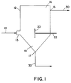
- the method of the present invention includes introducing a particle suspension 10 into a vessel 12 through inlet 13.
- Vessel 12 is typically cylindrically shaped, and has a top portion 14 and a conical bottom portion 15 with sloping side walls at approximately 60° angles. Each portion has a respective discharge outlet 16, 17.
- An impingement plate 20 is arranged within vessel 12 at a predetermined angle depending upon the particle sizes and flow rates of particle suspension 10. The angle of plate 20 allows for particle suspension 10 to be uniformly distributed within the vessel after impact with the plate.
- Impingement plate 20 can be attached to a plate rod 22 by any conventional means. Plate rod 22 allows for operator adjustment of the distance of plate 20 from inlet 13 from the exterior of vessel 12.
- particle suspension 10 will be uniformly distributed within vessel 12 upon impact with plate 20.
- the fine particles then rise to top portion 14.
- the contaminant particles, and residual fine particles settle to the bottom portion 15 of vessel 12.
- a fine particle stream 30 is removed through top discharge outlet 16 for packaging or further processing, while contaminant and residual fine particle stream 32 is removed through bottom discharge outlet 17 for disposal or further separation.
- Particle suspension 10 is typically comprised of a mixture of fine and contaminant particles in a gaseous medium.
- the fine particles typically have a particle diameter of less than about 45.0 microns (325 mesh size). Additionally, the fine particles typically have a bulk density of less than 160 kg/m 3 (10 lbs/ft 3 ).
- the contaminant particles are generally comprised of relatively large particles, coarse agglomerated particles, reaction by-products, extra-process materials, and/or unreacted raw materials. Generally, the contaminant particles, sometimes referred to as grit, have a particle size and bulk density greater than the fine particles. Examples of several fine particles which can be separated from contaminant particles suspended in a gaseous medium include, but are not limited to, fumed silicas, precipitated silicas, fumed alumina, zinc oxide fume and carbon black.
- Particle suspension 10 is carried in either a dilute or dense phase gas stream, the stream typically having a velocity greater than 0,025 m/s (5.0 feet per minute) depending upon the specific application and the type of fine particles desired to be separated.
- Any non-reactive gas can be used as the carrier gas for the fine and contaminant particles, such as nitrogen or air.
- air is used as the carrier gas due to its relative convenience and low cost.
- the particle suspension 10 is typically transferred directly from a reactor, other process vessel, or storage tank (not shown) into vessel 12.
- Several conventional methods can be used to create and transport particle suspension 10, including utilizing a fan or blower, a pump, a venturi, or a pneumatic transport system using a compressed gas.
- any of the known conventional methods may be appropriately controlled and adjusted by those skilled in the art to achieve the desired transport rate and fluidization of the fine and contaminant particles of particle suspension 10 into vessel 12. Similar particle transfer methods are utilized in the fine particle stream 30, as well as the contaminant and residual fine particle stream 32 to pull the fine and contaminant particles out of vessel 12 for further processing, packaging, or disposal.
- the present invention is particularly effective for separating fumed silica from contaminant particles.
- Fumed silica such as CAB-O-SIL® brand fumed silica (registered trademark of Cabot Corporation, Boston, MA) is produced by the hydrolysis of silicon tetrachloride vapor in a flame of hydrogen and oxygen. In the combustion process, molten spheres of silica are formed having nominal particle diameters averaging between about 0.007 to 0.027 micron. These molten spheres, termed primary particles, collide and fuse with one another to form branched, three dimensional, chain-like aggregates.
- the agglomerated fumed silica product typically has a nominal particle diameter of less than 45.0 microns and a bulk density of less than 80 kg/m 3 (5.0 lbs/ft 3 ).
- the fumed silica is typically subjected to a calcination process to reduce the hydrogen chloride adsorbed on its surface during the above described production process. After calcination, the fumed silica, and contaminants therein, is suspended in air and pumped to vessel 12.
- the contaminants present in the fumed silica particle suspension include silica and non-silica contaminants such as metal flakes, extra-process materials, fibers, metal oxides, as well as glass and ceramic-like fused silica particles.
- silica and non-silica contaminants such as metal flakes, extra-process materials, fibers, metal oxides, as well as glass and ceramic-like fused silica particles.
- PPM parts per million
- Conventional settling velocity calculations are used to determine the smallest particle sizes likely to be collected at any given velocity.
- the contaminant particle size and bulk density are, for the most part, greater than 45.0 microns and 160 kg/m 3 (10 lbs/ft 3 ), however it is not unusual to collect smaller and lighter particles.
- Particle suspension 10 is transported to vessel 12 at a predetermined velocity.
- the lowest flow rate must be great enough to fluidize the fumed silica, and can vary with the size and type of silica and operating conditions.
- the highest flow rate likewise, depends upon the desired fine particle size and the types of silica and contaminant particles.
- the velocity of particle suspension 10 is appropriately adjusted in order to achieve a bulk gas velocity within the vessel between about 0,025 m/s to about 0,10 m/s (5.0 to about 20.0 feet per minute).
- the bulk gas velocity is the total gaseous flow of particle suspension 10 in meter (cubic feet) per second (minute) divided by the cross sectional area of vessel 12.
- the bulk gas velocity within the vessel is between about 0,045 m/s to about 0,07 m/s (9.0 to about 14.0 feet per minute).
- Particle suspension 10 enters vessel 12 through inlet 13, where it is directed into impingement plate 20. After impact with impingement plate 20, particle suspension 10 is uniformly distributed within vessel 12. As is known to those skilled in the art, the heavy, coarse contaminant particles will exhibit a relatively faster settling velocity than the fine, low density, fumed silica particles, and settle to bottom portion 15. The fumed silica particles will rise to top portion 14 with the carrier gas, where they are removed through top discharge outlet 16, forming the fine particle stream 30.
- Stream 30 typically includes between 0 to 25 PPM contaminant particles, with a mean of about 5 PPM. Meanwhile, the contaminant particles, as well as a small amount of residual fumed silica, are periodically removed through bottom discharge outlet 17, forming the contaminant and residual particle stream 32.
- Impingement plate 20 is arranged within vessel 12 at a predetermined angle of between about 0° to about 90°, relative to the central axis of vessel 12 such that particle suspension 10 will impact a large portion of plate 20.
- Plate 20 is sized, in any planar geometric shape, larger than the cross-sectional diameter of inlet 13 and the incoming particle suspension 10.
- Plate 20 is typically held within vessel 12 with a plate rod 22, which provides for operator adjustment of the distance of plate 20 from inlet 13 from the exterior of the vessel.
- Other methods of mounting plate 20 within vessel 12 include, but are not limited to, adjustable or fixed braces or welding.
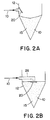
- impingement plate 20 is shown in various positions with vessel 12. As noted above, impingement plate 20 is arranged within vessel 12 at a predetermined angle, depending upon the particle sizes and flow rates of the incoming particle suspension 10.
- FIG. 1 illustrates a vertical impingement plate 20, angled at 0° relative to the central axis of vessel 12, attached to plate rod 22. The particle suspension 10 is perpendicularly directed into impingement plate 20, which uniformly distributes particle suspension 10 within vessel 12 (net shown).
- FIG. 2A illustrates an alternative arrangement of impingement 20.
- Plate 20 is attached to a wall of vessel 12, above inlet 13, and is angled downwardly such that the incoming particle suspension 10 is directed into bottom portion 15, wherein it is uniformly distributed prior to the settling of the heavier, coarser contaminant particles.
- FIG. 2B illustrates an alternative method of introducing the particle suspension 10 into vessel 12, as well as arranging impingement plate 20.
- a directing conduit, or tube 26 is used to direct particle suspension 10 into the horizontally positioned impingement plate 20.
- impingement plate 20 may be mounted within vessel 12 in any manner known to those skilled in the art. The particle suspension is uniformly distributed in bottom portion 15 after impact with plate 20.
- Classifier 40 may be a non-mechanical or a mechanical type classifier.
- a non-mechanical type classifier such as a cyclone separator, is preferred because of the relative low cost of installation, operation and maintenance.
- a cyclone separator operates by introducing a particle-laden gas into a cylindrical or conical chamber tangentially. The heavier and coarser contaminant particles will be discharged through a central bottom discharge outlet, while the lighter, fine particles, such as fumed silica, will exit through the top gas discharge outlet.
- the residual fine particle stream 42 is recycled to vessel 12, with particle suspension 10, into inlet 13.
- the overall process within vessel 12 as described above, is repeated as the recycle stream 42 and particle suspension 10 impact impingement plate 20.
- the particles are uniformly dispersed within vessel 12, where the contaminant particles settle and are removed through bottom discharge outlet 17, while the fine particles rise and are removed through top discharge outlet 16.
- the contaminant discharge stream 44 leaves classifier 40 through the central bottom discharge outlet, and is fed into a holding tank 46 where it is accumulated before being disposed through disposal stream 48.
- the present invention teaches an improved method for separating fine particles from contaminant particles in a gaseous medium.
- a system with no moving parts it provides for a cost effective and efficient contamination removal process which is relatively insensitive to incoming velocities and varying contaminant levels.
- the present invention allows for operating flexibility, a low pressure drop, and a lower solids, i.e. fine particle, loss relative to conventional classification.
Landscapes
- Chemical & Material Sciences (AREA)
- Organic Chemistry (AREA)
- Inorganic Chemistry (AREA)
- Combined Means For Separation Of Solids (AREA)
- Silicon Compounds (AREA)
- Devices And Processes Conducted In The Presence Of Fluids And Solid Particles (AREA)
Claims (15)
- Verfahren zum Trennen von pyrogener Kieselsäure mit einem nominalen Partikeldurchmesser von weniger als 45 µm und einer Fülldichte von weniger als ungefähr 160 kg/m3 (10 lbs/ft3) von kontaminierenden Partikeln mit einem Partikeldurchmesser und einer Fülldichte, die größer als die der pyrogener Kieselsäure sind, die einem Gasstrom suspendiert sind mit den Schritten:Einführen des Gasstroms (10) einer vorbestimmten Geschwindigkeit in ein Gefäß (12), die groß genug ist, die pyrogene Kieselsäure aufwirbeln zu lassen und eine mittlere Korngeschwindigkeit innerhalb des Gefäßes (12) von 0,05 bis 0,10 m/s (5,0 bis 20,0 ft/min) zu erreichen, wobei das Gefäß (12) ein Ober- (14) und ein Unterteil (15) aufweist, die beide eine Abführöffnung aufweisen;Führen des Gasstroms auf eine Aufprallplatte (20), wobei diese Platte (20) in dem Gefäß (12) unter einem vorbestimmten Winkel derart angeordnet ist, daß der Gasstrom nach dem Aufprallen auf besagte Platte gleichmäßig innerhalb des Gefäßes (12) verteilt wird; so daßdie pyrogene Kieselsäure in das Gefäßoberteil (14) schwebt und die kontaminierenden Partikel und restliche pyrogene Kieselsäure sich im Gefäßunterteil (15) ablagern;Entfernen der pyrogenen Kieselsäure durch die obere Abführöffnung (16) und Entfernen der kontaminierenden Partikel und restlichen pyrogenen Kieselsäure durch die untere Abführöffnung (17).
- Verfahren nach Anspruch 1 mit den zusätzlichen Schritten:Einführen der kontaminierenden Partikel und restlichen pyrogenen Kieselsäure (32) in einen Klassierer (40), um die restlichen pyrogene Kieselsäure (42), die sich mit den kontaminierenden Partikeln im Gefäß (12) abgelagert hat, abzutrennen;Zurückführen der restlichen pyrogenen Kieselsäure in das Gefäß (12); undAbführen der kontaminierenden Partikel (44).
- Verfahren nach Anspruch 2, dadurch gekennzeichnet, daß der Klassierer ein rotierender Klassierer ist.
- Verfahren nach einem der Ansprüche 1 bis 3, dadurch gekennzeichnet, daß die pyrogene Kieselsäure einen nominalen Partikeldurchmesser von etwa 1,0 bis etwa 45,0 µm aufweist.
- Verfahren nach einem der Ansprüche 1 bis 4, dadurch gekennzeichnet, daß die pyrogene Kieselsäure eine Fülldichte von weniger als 160 kg/m3 (10 lbs/ft3) aufweist.
- Verfahren nach Anspruch 5, dadurch gekennzeichnet, daß die pyrogene Kieselsäure eine Fülldichte von weniger als etwa 80 kg/m3 (5 lbs/ft3) aufweist.
- Verfahren nach einem der Ansprüche 1 bis 6, dadurch gekennzeichnet, daß die pyrogene Kieselsäure und die kontaminierenden Partikel in einem verdünnten Gasphasenstrom suspendiert sind.
- Verfahren nach einem der Ansprüche 1 bis 6, dadurch gekennzeichnet, daß die pyrogene Kieselsäure und die kontaminierenden Partikel in einem dichten Gasphasenstrom suspendiert sind.
- Verfahren nach einem der Ansprüche 1 bis 8, dadurch gekennzeichnet, daß die mittlere Korngeschwindigkeit in dem Gefäß (12) zwischen 0,045 und 0,07 m/s (9 ft/min bis ungefähr 14/ft/min) beträgt.
- Verfahren nach einem der Ansprüche 1 bis 9, dadurch gekennzeichnet, daß die Aufprallplatte (20) in dem Gefäß unter einem vorbestimmten Winkel zwischen 0° und 90° relativ zur zentralen Achse (12) angeordnet ist.
- Verfahren nach Anspruch 10, dadurch gekennzeichnet, daß der Abstand der Aufprallplatte (20) zur Eintrittsöffnung für die pyrogene Kieselsäure (13) anpassbar ist.
- Verfahren nach Anspruch 10 oder 11, dadurch gekennzeichnet, daß die Größe der Aufprallplatte (20) größer ist als der Innendurchmesser der Eintrittsöffnung (13) für die pyrogene Kieselsäure und des Durchmessers des eintretenden Partikelgasstromes (10) ist.
- Verfahren nach einem der Ansprüche 10 bis 12, dadurch gekennzeichnet, daß die Aufprallplatte (20) eben ist.
- Verfahren nach einem der Ansprüche 10 bis 13, dadurch gekennzeichnet, daß der Partikelgasstrom (10) horizontal gegen die Aufprallplatte (20) geführt wird.
- Verfahren nach einem der Ansprüche 10 bis 13, daß der Partikelgasstrom (10) senkrecht gegen die Aufprallplatte (20) geführt wird.
Priority Applications (1)
| Application Number | Priority Date | Filing Date | Title |
|---|---|---|---|
| EP98124676A EP0906891A3 (de) | 1993-01-19 | 1994-01-14 | Vorrichtung zur Klassifizierung feiner Teilchen |
Applications Claiming Priority (3)
| Application Number | Priority Date | Filing Date | Title |
|---|---|---|---|
| US6359 | 1993-01-19 | ||
| US08/006,359 US5348163A (en) | 1993-01-19 | 1993-01-19 | Method and apparatus for separating fine particles |
| PCT/US1994/000477 WO1994016995A1 (en) | 1993-01-19 | 1994-01-14 | Fine particle classifier |
Related Child Applications (1)
| Application Number | Title | Priority Date | Filing Date |
|---|---|---|---|
| EP98124676.2 Division-Into | 1998-12-24 |
Publications (2)
| Publication Number | Publication Date |
|---|---|
| EP0680455A1 EP0680455A1 (de) | 1995-11-08 |
| EP0680455B1 true EP0680455B1 (de) | 2000-04-19 |
Family
ID=21720510
Family Applications (2)
| Application Number | Title | Priority Date | Filing Date |
|---|---|---|---|
| EP94906071A Expired - Lifetime EP0680455B1 (de) | 1993-01-19 | 1994-01-14 | Verfahren ZUR KLASSIFIZIERUNG FEINER TEILCHEN |
| EP98124676A Withdrawn EP0906891A3 (de) | 1993-01-19 | 1994-01-14 | Vorrichtung zur Klassifizierung feiner Teilchen |
Family Applications After (1)
| Application Number | Title | Priority Date | Filing Date |
|---|---|---|---|
| EP98124676A Withdrawn EP0906891A3 (de) | 1993-01-19 | 1994-01-14 | Vorrichtung zur Klassifizierung feiner Teilchen |
Country Status (8)
| Country | Link |
|---|---|
| US (1) | US5348163A (de) |
| EP (2) | EP0680455B1 (de) |
| JP (1) | JPH08505834A (de) |
| KR (1) | KR100294982B1 (de) |
| CN (1) | CN1047364C (de) |
| AU (1) | AU5994494A (de) |
| DE (1) | DE69424036T2 (de) |
| WO (1) | WO1994016995A1 (de) |
Families Citing this family (16)
| Publication number | Priority date | Publication date | Assignee | Title |
|---|---|---|---|---|
| GB2281520A (en) * | 1993-09-07 | 1995-03-08 | Macbride Thomas Joseph | Separation of re-usable abrasive particles by impact against baffle in suction chamber |
| FR2745086B1 (fr) * | 1996-02-15 | 1998-03-13 | Commissariat Energie Atomique | Selecteur de particules chargees, en fonction de leur mobilite electrique et de leur temps de relaxation |
| DE19855816A1 (de) * | 1998-12-03 | 2000-06-08 | Heraeus Quarzglas | Verfahren für die Reinigung von Si0¶2¶-Körnung und Vorrichtung zur Durchführung des Verfahrens |
| JP4399966B2 (ja) * | 2000-07-28 | 2010-01-20 | パナソニック株式会社 | 風力選別装置 |
| US7267233B2 (en) * | 2004-01-07 | 2007-09-11 | Eastman Chemical Company | In-line classifier for powdered products |
| CN100369942C (zh) * | 2006-01-26 | 2008-02-20 | 吉林市吉清科技开发有限公司 | 气相流化床乙烯聚合催化剂微球形二氧化硅载体的制备方法及设备 |
| CN102083601A (zh) | 2008-06-26 | 2011-06-01 | 凯斯勒废物系统公司 | 废弃物存储一体化的系统与方法 |
| US8118173B2 (en) * | 2008-12-03 | 2012-02-21 | Westlake Longview Corp. | Streamer trap assembly |
| HRP20171259T1 (hr) | 2011-06-03 | 2017-10-20 | Accordant Energy, Llc | Postupak za proizvodnju modificiranog tehničkog goriva iz otpada |
| JP6044204B2 (ja) * | 2012-09-07 | 2016-12-14 | 株式会社リコー | 異物分離装置及び異物分離方法 |
| CN105127099B (zh) * | 2015-09-30 | 2017-12-08 | 韶关市丰一工贸有限公司 | 一种无网式谷物风分离装置 |
| DE102018120362A1 (de) * | 2018-08-21 | 2020-02-27 | Horiba Europe Gmbh | Partikelmesssystem mit einer Verdünnungsvorrichtung und Verfahren zur Partikelmessung |
| CN110586288A (zh) * | 2018-09-07 | 2019-12-20 | 上海市市政规划设计研究院有限公司 | 一种用于分散粘性物料的方法及其装置 |
| CN112716532B (zh) * | 2020-12-28 | 2024-04-30 | 中国科学院合肥物质科学研究院 | 一种呼气气溶胶采集检测装置及其检测方法 |
| CN113446839A (zh) * | 2021-06-25 | 2021-09-28 | 安徽正阳机械科技有限公司 | 一种具有安全余热回收的旋转式谷物干燥机 |
| CN114655711B (zh) * | 2022-05-05 | 2023-07-18 | 江苏威马悦达智能装备有限公司 | 一种小型零部件气动送料缓冲装置 |
Family Cites Families (52)
| Publication number | Priority date | Publication date | Assignee | Title |
|---|---|---|---|---|
| US1986301A (en) * | 1935-01-01 | Blending and air separation of | ||
| US272475A (en) * | 1883-02-20 | prinz | ||
| US1272311A (en) * | 1918-07-09 | Williams Patent Crusher & Pulv | Pneumatic separating system. | |
| US901474A (en) * | 1905-08-02 | 1908-10-20 | Robert Hallowell Richards | Apparatus for separating and classifying minerals. |
| US1146624A (en) * | 1914-12-23 | 1915-07-13 | Frederick W Huber | Method and apparatus for classifying crushed material. |
| US1457110A (en) * | 1921-04-06 | 1923-05-29 | Rubert M Gay | Air separator |
| US1581241A (en) * | 1925-05-04 | 1926-04-20 | Albert H Stebbins | Classifier |
| US1660682A (en) * | 1926-01-08 | 1928-02-28 | Albert H Stebbins | Air-blast classifier |
| US1801195A (en) * | 1927-10-31 | 1931-04-14 | Hydrotator Company | Process of and apparatus for separating mixed materials |
| US1897367A (en) * | 1931-06-16 | 1933-02-14 | Eldridge George Emmet | Corn sheller separator |
| US2022585A (en) * | 1933-08-12 | 1935-11-26 | Henry M Chance | Separating process |
| US2214434A (en) * | 1938-04-21 | 1940-09-10 | Joseph C Nelms | Apparatus for cleaning loose materials |
| US2278092A (en) * | 1939-07-14 | 1942-03-31 | Johns Manville | Apparatus for the manufacture of mineral wool |
| US2461584A (en) * | 1944-06-14 | 1949-02-15 | Smidth & Co As F L | Air separation method for slurry separation |
| US2446140A (en) * | 1945-02-16 | 1948-07-27 | Roberts & Schaefer Co | Apparatus for pneumatically separating relatively moist comminuted material |
| US2561396A (en) * | 1946-10-09 | 1951-07-24 | Standard Oil Dev Co | Segregation of solid particles |
| US3130008A (en) * | 1949-11-23 | 1964-04-21 | Cabot Corp | Method of preparing metallic oxides by hydrolysis of metallic halides |
| US2634858A (en) * | 1949-11-28 | 1953-04-14 | Vahey Llewellyn | Pneumatic separator or classifier |
| DE900339C (de) * | 1951-07-05 | 1953-12-21 | Degussa | Verfahren und Vorrichtung zur Herstellung von kolloidaler Kieselsaeure in Aerogelform |
| US2683685A (en) * | 1951-07-28 | 1954-07-13 | Standard Oil Dev Co | Elutriation of finely divided solids |
| US2870001A (en) * | 1952-06-26 | 1959-01-20 | Texas Gulf Sulphur Co | Method of fluidization |
| US2850162A (en) * | 1954-08-11 | 1958-09-02 | Buehler Ag Geb | Separators for pneumatically conveyed aggregate goods |
| US2968069A (en) * | 1956-01-30 | 1961-01-17 | Johns Manville | Method and apparatus for cleaning and felting fibrous material |
| US2968400A (en) * | 1957-11-12 | 1961-01-17 | Clute Corp | Material collector |
| US3104155A (en) * | 1958-11-03 | 1963-09-17 | Exxon Research Engineering Co | Separation of heat carrier from fluidized bed |
| US3113099A (en) * | 1960-02-15 | 1963-12-03 | Polysins G M B H | Device for sorting material according to granular size and weight |
| US3288285A (en) * | 1963-07-09 | 1966-11-29 | Gen Mills Inc | Air classifier |
| US3349912A (en) * | 1964-10-12 | 1967-10-31 | Head Wrightson & Co Ltd | Fluidized bed separator |
| US3362531A (en) * | 1964-10-29 | 1968-01-09 | Sinclair Research Inc | Method of separating catalyst particles into fractions of differing surface area |
| GB1068778A (en) * | 1965-04-27 | 1967-05-17 | Ambuco Ltd | Improvements in or relating to classification apparatus |
| US3426893A (en) * | 1967-04-18 | 1969-02-11 | Kennedy Van Saun Co | Method and apparatus for classifying finely-divided solids carried in a gas stream |
| US3447678A (en) * | 1967-04-20 | 1969-06-03 | Donald L Henry | Method for separating expanded perlite with minimum particle breakage |
| US3482692A (en) * | 1968-10-02 | 1969-12-09 | Atomic Energy Commission | Elutriator |
| FI54681C (fi) * | 1971-09-27 | 1979-02-12 | Insinoeoeritoimisto Engineerin | Pneumatiskt klassificeringsfoerfarande och pneumatisk klassificerare foer utfoerande av foerfarandet |
| US3865242A (en) * | 1972-12-15 | 1975-02-11 | Combustion Eng | Upstream classifier for a multi-separator |
| US3883423A (en) * | 1973-08-01 | 1975-05-13 | Aerofall Mills Ltd | Vertical classifier |
| US4132634A (en) * | 1974-09-17 | 1979-01-02 | Hans Rumpf | Method of an apparatus for sifting particulate material in a cross-current |
| US4055486A (en) * | 1975-08-11 | 1977-10-25 | Occidental Petroleum Corporation | Method and apparatus for handling solid fluidized particles |
| DE2538190C3 (de) * | 1975-08-27 | 1985-04-04 | Rumpf, geb. Strupp, Lieselotte Clara, 7500 Karlsruhe | Verfahren und Vorrichtung zur kontinuierlichen Fliehkraftsichtung eines stetigen Mengenstroms von körnigem Gut |
| US4159941A (en) * | 1976-05-21 | 1979-07-03 | Allied Industries, Inc. | Separator |
| US4169714A (en) * | 1977-01-14 | 1979-10-02 | A.P.T., Inc. | Removal of fine particles from a gas stream by solid particle addition in venturi contactor |
| US4125456A (en) * | 1977-03-22 | 1978-11-14 | Phillips Petroleum Company | Method and apparatus for separating particulate materials |
| GB1599547A (en) * | 1978-05-25 | 1981-10-07 | Motherwell Bridge Tacol Ltd | Air classification apparatus |
| US4299693A (en) * | 1980-04-30 | 1981-11-10 | Allied Industries | Separator |
| US4299694A (en) * | 1980-08-25 | 1981-11-10 | The Direct Reduction Corporation | Method and apparatus for char separation from the discharge materials of an iron oxide reducing kiln |
| JPS5813724A (ja) * | 1980-12-05 | 1983-01-26 | ツリユツラ−・ゲゼルシヤフト・ミツト・ベシユレンクテル・ハフツング・ウント・コンパニ−・コマンデイトゲゼルシヤフト | 繊維材料から異物及び高比重分を除去する方法及び装置 |
| CH652940A5 (de) * | 1982-01-09 | 1985-12-13 | Sandoz Ag | Verfahren zur herstellung nicht staubender granulate und vorrichtung hierfuer. |
| DE3409814A1 (de) * | 1984-03-16 | 1985-09-19 | Waeschle Maschinenfabrik Gmbh, 7980 Ravensburg | Gegenstromsichter |
| US4657667A (en) * | 1984-04-05 | 1987-04-14 | The University Of Toronto Innovations Foundation | Particle classifier |
| GB2174621B (en) * | 1985-04-18 | 1988-11-16 | Canon Kk | Process for producing toner for developing electrostatic images and apparatus therefor |
| US4743363A (en) * | 1986-09-25 | 1988-05-10 | The Dexter Corporation | Classifying cyclone |
| US4946044A (en) * | 1988-05-18 | 1990-08-07 | Kennedy Van Saup Corporation | Aeration separator |
-
1993
- 1993-01-19 US US08/006,359 patent/US5348163A/en not_active Expired - Lifetime
-
1994
- 1994-01-14 EP EP94906071A patent/EP0680455B1/de not_active Expired - Lifetime
- 1994-01-14 EP EP98124676A patent/EP0906891A3/de not_active Withdrawn
- 1994-01-14 JP JP6517101A patent/JPH08505834A/ja not_active Ceased
- 1994-01-14 CN CN94190963A patent/CN1047364C/zh not_active Expired - Fee Related
- 1994-01-14 WO PCT/US1994/000477 patent/WO1994016995A1/en not_active Ceased
- 1994-01-14 DE DE69424036T patent/DE69424036T2/de not_active Expired - Lifetime
- 1994-01-14 AU AU59944/94A patent/AU5994494A/en not_active Abandoned
- 1994-01-14 KR KR1019950702948A patent/KR100294982B1/ko not_active Expired - Fee Related
Also Published As
| Publication number | Publication date |
|---|---|
| DE69424036D1 (de) | 2000-05-25 |
| AU5994494A (en) | 1994-08-15 |
| DE69424036T2 (de) | 2000-12-14 |
| JPH08505834A (ja) | 1996-06-25 |
| KR960700193A (ko) | 1996-01-19 |
| EP0906891A2 (de) | 1999-04-07 |
| WO1994016995A1 (en) | 1994-08-04 |
| KR100294982B1 (ko) | 2001-09-17 |
| EP0680455A1 (de) | 1995-11-08 |
| US5348163A (en) | 1994-09-20 |
| CN1047364C (zh) | 1999-12-15 |
| CN1116845A (zh) | 1996-02-14 |
| EP0906891A3 (de) | 2000-01-12 |
| HK1015134A1 (en) | 1999-10-08 |
Similar Documents
| Publication | Publication Date | Title |
|---|---|---|
| EP0680455B1 (de) | Verfahren ZUR KLASSIFIZIERUNG FEINER TEILCHEN | |
| JP4612595B2 (ja) | シリコンを粉砕する方法および装置 | |
| EP0948410B1 (de) | Verfahren und vorrichtung zur verarbeitung und behandlung von partikelförmigem material | |
| EP0616856B1 (de) | Apparat zur Entfernung feiner Partikel von synthetischen Harzkugeln | |
| US4526678A (en) | Apparatus and method for separating large from small particles suspended in a gas stream | |
| US4065271A (en) | Process of separating hydrogen fluoride from gases | |
| US4773189A (en) | Separation system for polymeric blast media | |
| US3878091A (en) | Method for pneumatic classification and a pneumatic classifier | |
| US3975263A (en) | Material separation apparatus and method | |
| WO2003037534A1 (en) | Method apparatus for separating unwanted matter from granular material | |
| JP2548519B2 (ja) | 流動層分級器 | |
| US3956106A (en) | Apparatus and process for the production of grit free finely dispersed pigments | |
| CN106413922A (zh) | 用于净化和精细分拣颗粒冶金废物粉末的设备以及用于净化和精细分拣颗粒冶金废物粉末的方法 | |
| RU2132242C1 (ru) | Способ аэродинамической классификации металлических порошков и установка для его осуществления | |
| HK1015134B (en) | A method of classifying fine particles | |
| HK1024901A (en) | Fine particle classifier | |
| KR20030085505A (ko) | 건식 분리 방법 및 분리 장치 | |
| US5122348A (en) | Method of slurrying partially calcined alumina dust | |
| JPS63501776A (ja) | 圧力室粉砕機の粉砕効率改良のための方法と装置 | |
| AU635327B2 (en) | Method for reducing wear on nozzles or other supply means | |
| EP4037845B1 (de) | Vorrichtung zum sortieren von pulverteilchen | |
| SU1738389A1 (ru) | Классификатор | |
| KR100807710B1 (ko) | 실리콘 분쇄 방법 및 장치 | |
| RU2047404C1 (ru) | Установка для разделения порошкообразных материалов по крупности | |
| SU1535655A1 (ru) | Способ центробежной классификации порошков |
Legal Events
| Date | Code | Title | Description |
|---|---|---|---|
| PUAI | Public reference made under article 153(3) epc to a published international application that has entered the european phase |
Free format text: ORIGINAL CODE: 0009012 |
|
| 17P | Request for examination filed |
Effective date: 19950803 |
|
| AK | Designated contracting states |
Kind code of ref document: A1 Designated state(s): BE DE FR GB |
|
| 17Q | First examination report despatched |
Effective date: 19951109 |
|
| GRAG | Despatch of communication of intention to grant |
Free format text: ORIGINAL CODE: EPIDOS AGRA |
|
| GRAG | Despatch of communication of intention to grant |
Free format text: ORIGINAL CODE: EPIDOS AGRA |
|
| GRAH | Despatch of communication of intention to grant a patent |
Free format text: ORIGINAL CODE: EPIDOS IGRA |
|
| GRAH | Despatch of communication of intention to grant a patent |
Free format text: ORIGINAL CODE: EPIDOS IGRA |
|
| GRAA | (expected) grant |
Free format text: ORIGINAL CODE: 0009210 |
|
| AK | Designated contracting states |
Kind code of ref document: B1 Designated state(s): BE DE FR GB |
|
| REF | Corresponds to: |
Ref document number: 69424036 Country of ref document: DE Date of ref document: 20000525 |
|
| ET | Fr: translation filed | ||
| PLBE | No opposition filed within time limit |
Free format text: ORIGINAL CODE: 0009261 |
|
| STAA | Information on the status of an ep patent application or granted ep patent |
Free format text: STATUS: NO OPPOSITION FILED WITHIN TIME LIMIT |
|
| 26N | No opposition filed | ||
| REG | Reference to a national code |
Ref country code: GB Ref legal event code: IF02 |
|
| PGFP | Annual fee paid to national office [announced via postgrant information from national office to epo] |
Ref country code: BE Payment date: 20080201 Year of fee payment: 15 |
|
| PG25 | Lapsed in a contracting state [announced via postgrant information from national office to epo] |
Ref country code: BE Free format text: LAPSE BECAUSE OF NON-PAYMENT OF DUE FEES Effective date: 20090131 |
|
| PGFP | Annual fee paid to national office [announced via postgrant information from national office to epo] |
Ref country code: DE Payment date: 20110228 Year of fee payment: 18 Ref country code: FR Payment date: 20110304 Year of fee payment: 18 |
|
| PGFP | Annual fee paid to national office [announced via postgrant information from national office to epo] |
Ref country code: GB Payment date: 20110221 Year of fee payment: 18 |
|
| REG | Reference to a national code |
Ref country code: DE Ref legal event code: R082 Ref document number: 69424036 Country of ref document: DE Representative=s name: MEHLER ACHLER PATENTANWAELTE PARTNERSCHAFT MBB, DE Ref country code: DE Ref legal event code: R082 Ref document number: 69424036 Country of ref document: DE Representative=s name: MEHLER ACHLER PATENTANWAELTE, DE |
|
| GBPC | Gb: european patent ceased through non-payment of renewal fee |
Effective date: 20120114 |
|
| REG | Reference to a national code |
Ref country code: FR Ref legal event code: ST Effective date: 20120928 |
|
| PG25 | Lapsed in a contracting state [announced via postgrant information from national office to epo] |
Ref country code: GB Free format text: LAPSE BECAUSE OF NON-PAYMENT OF DUE FEES Effective date: 20120114 Ref country code: DE Free format text: LAPSE BECAUSE OF NON-PAYMENT OF DUE FEES Effective date: 20120801 |
|
| REG | Reference to a national code |
Ref country code: DE Ref legal event code: R119 Ref document number: 69424036 Country of ref document: DE Effective date: 20120801 |
|
| PG25 | Lapsed in a contracting state [announced via postgrant information from national office to epo] |
Ref country code: FR Free format text: LAPSE BECAUSE OF NON-PAYMENT OF DUE FEES Effective date: 20120131 |