EP0680205A2 - Abbildungssystem zur Objektsegmentierung - Google Patents
Abbildungssystem zur Objektsegmentierung Download PDFInfo
- Publication number
- EP0680205A2 EP0680205A2 EP95101352A EP95101352A EP0680205A2 EP 0680205 A2 EP0680205 A2 EP 0680205A2 EP 95101352 A EP95101352 A EP 95101352A EP 95101352 A EP95101352 A EP 95101352A EP 0680205 A2 EP0680205 A2 EP 0680205A2
- Authority
- EP
- European Patent Office
- Prior art keywords
- image
- scene
- light
- background
- input device
- Prior art date
- Legal status (The legal status is an assumption and is not a legal conclusion. Google has not performed a legal analysis and makes no representation as to the accuracy of the status listed.)
- Withdrawn
Links
- 238000003384 imaging method Methods 0.000 title claims description 15
- 230000011218 segmentation Effects 0.000 title description 2
- 238000012545 processing Methods 0.000 claims abstract description 20
- 238000000034 method Methods 0.000 claims abstract description 17
- 230000004313 glare Effects 0.000 claims abstract description 14
- 238000005286 illumination Methods 0.000 claims description 23
- 230000010287 polarization Effects 0.000 claims description 9
- 230000001360 synchronised effect Effects 0.000 claims description 5
- 230000005055 memory storage Effects 0.000 claims description 2
- 230000000694 effects Effects 0.000 abstract description 4
- 230000004438 eyesight Effects 0.000 description 5
- 238000010586 diagram Methods 0.000 description 4
- 230000006870 function Effects 0.000 description 4
- 238000005259 measurement Methods 0.000 description 4
- 238000000926 separation method Methods 0.000 description 3
- 239000003086 colorant Substances 0.000 description 2
- 239000011521 glass Substances 0.000 description 2
- 238000002310 reflectometry Methods 0.000 description 2
- 238000005282 brightening Methods 0.000 description 1
- 238000012937 correction Methods 0.000 description 1
- 230000001419 dependent effect Effects 0.000 description 1
- 238000002347 injection Methods 0.000 description 1
- 239000007924 injection Substances 0.000 description 1
- 238000007689 inspection Methods 0.000 description 1
- 239000000203 mixture Substances 0.000 description 1
- 230000005855 radiation Effects 0.000 description 1
- 230000003595 spectral effect Effects 0.000 description 1
- 238000001228 spectrum Methods 0.000 description 1
- 238000012360 testing method Methods 0.000 description 1
- 230000001960 triggered effect Effects 0.000 description 1
- 230000000007 visual effect Effects 0.000 description 1
Images
Classifications
-
- H—ELECTRICITY
- H04—ELECTRIC COMMUNICATION TECHNIQUE
- H04N—PICTORIAL COMMUNICATION, e.g. TELEVISION
- H04N5/00—Details of television systems
- H04N5/222—Studio circuitry; Studio devices; Studio equipment
- H04N5/262—Studio circuits, e.g. for mixing, switching-over, change of character of image, other special effects ; Cameras specially adapted for the electronic generation of special effects
- H04N5/272—Means for inserting a foreground image in a background image, i.e. inlay, outlay
- H04N5/275—Generation of keying signals
-
- G—PHYSICS
- G06—COMPUTING; CALCULATING OR COUNTING
- G06T—IMAGE DATA PROCESSING OR GENERATION, IN GENERAL
- G06T5/00—Image enhancement or restoration
- G06T5/50—Image enhancement or restoration using two or more images, e.g. averaging or subtraction
-
- G—PHYSICS
- G06—COMPUTING; CALCULATING OR COUNTING
- G06T—IMAGE DATA PROCESSING OR GENERATION, IN GENERAL
- G06T7/00—Image analysis
- G06T7/10—Segmentation; Edge detection
- G06T7/11—Region-based segmentation
-
- G—PHYSICS
- G06—COMPUTING; CALCULATING OR COUNTING
- G06T—IMAGE DATA PROCESSING OR GENERATION, IN GENERAL
- G06T7/00—Image analysis
- G06T7/10—Segmentation; Edge detection
- G06T7/194—Segmentation; Edge detection involving foreground-background segmentation
-
- H—ELECTRICITY
- H04—ELECTRIC COMMUNICATION TECHNIQUE
- H04N—PICTORIAL COMMUNICATION, e.g. TELEVISION
- H04N23/00—Cameras or camera modules comprising electronic image sensors; Control thereof
- H04N23/70—Circuitry for compensating brightness variation in the scene
- H04N23/74—Circuitry for compensating brightness variation in the scene by influencing the scene brightness using illuminating means
Definitions
- This invention relates to the field of image processing and computer vision. More specifically, the invention relates to an apparatus and method for taking images of objects independent of the background and/or of the ambient illumination.
- a scene includes a background and one or more objects.
- an analog image from a camera is converted to a discrete representation by dividing the picture into a fixed number of locations called picture elements, or pixels, and quantizing the brightness of the image at those picture elements into a fixed number of values.
- picture elements or pixels
- quantizing the brightness of the image at those picture elements into a fixed number of values.
- This processing also called image processing or computer vision, includes modifying the scene image or obtaining properties from the scene image such as the identity or location of the object in the scene.
- the object (or objects) that is (are) of interest are imaged along with the scene surroundings. These surroundings are called the background.
- the background is usually further away from the camera than the object(s) of interest.
- image processing it is necessary to separate the object(s) image from the background image of the scene. This separation is called figure/ground separation or segmentation.
- Objects in the scene are illuminated when light falls on the object(s).
- Ambient illumination is the illumination due to light sources occurring in the environment such as the sun outdoors and room lights indoors. Thus ambient illumination is illumination from any light source except the special lights used specifically for imaging an object.
- Some illuminating light is reflected from the object(s). Some reflected light may be glare (also called specular reflection) which is the high amount of light reflected off a shiny object. The color of the glare is mostly that of the illuminating light (as opposed to the natural color of the object).
- Prior art image processing systems can not easily separate objects of interest from the background of the scene. For example, there are systems which inspect or recognize parts in an assembly line from an image of those parts. There are special effects systems which mix the image of actors with special backgrounds which may be created separately by computers. These systems obtain an image of the object amenable to processing by presenting the object against a background which is readily and simply distinguishable from the object. For instance, parts inspection systems may image the parts against a black or white surface. Special effects systems usually require the actors to be imaged before a blue surface. These and many other systems will fail if the background is arbitrary and not specially controlled.
- some prior art systems have difficulty determining object properties in varying ambient light.
- image processing and computer vision systems work by making measurements on the image. Many such systems measure the color or intensity in the image. These color and intensity measurements depend on the the light illuminating the imaged object.
- these systems require either the object to be enclosed in a specially lighted chamber or need to control all the light in space the image is taken, i.e. all the light on a factory floor or a studio. Therefore, systems which measure object color and/or intensity or depend on measurement of image color and/or intensity may fail if the object is presented in different ambient light.
- Glare reflected from shiny surfaces also presents problems that are difficult to solve for many prior art image processing systems.
- Image processing and computer vision systems have difficulty imaging shiny surfaces such as glass plates or metallic objects due the glare generated by light reflecting off these shiny surfaces. This is because glare reflected into the imaging system obscures the object, masks certain surface features, or is interpreted incorrectly as a intentional mark.
- An object of this invention is an improved apparatus and method for imaging objects independently and separately of the background.
- a further object of this invention is an improved apparatus and method for imaging objects with precisely controlled light independent and unaffected by any ambient illumination.
- Another object of this invention is an improved apparatus and method for removing glare from images of shiny objects.
- Another object of this invention is an improved apparatus and method for imaging and segmenting objects independent of background, ambient illumination and glare.
- the present invention is a novel system and method for image processing so that one or more objects in the scene can be segmented from the scene background.
- the invention comprises a light source (or other electromagnetic or acoustic radiation source) placed at a distance from the object(s) so that the object appears brighter to a image input device than when the light is turned off or is reduced in intensity.
- the background must exhibit less of a brightening.
- Two images of the object are taken in which the light is controlled to illuminate the object more in one image than the other.
- the images are compared, preferably on a pixel by pixel basis, and the parts of the image with increased intensity are segmented as corresponding to the object.
- the image input device and the light source are placed in an opaque enclosure with an opening through which the image input device can view the object and the light can illuminate the object.
- the object is placed close to this opening so that the part of the object viewed by the image input device is illuminated almost entirely by the light and not by the ambient illumination. In this manner, the effects of ambient illumination are eliminated from the imaging.
- the light is linearly polarized (either inherently or through use of a filter) and the image input device is fitted with a linear polarization filter whose direction of polarization is orthogonal to the direction of polarization of the light.
- the glare or specular reflection maintains the polarization of the light source and thus does not pass through the filter on the image input device while the diffuse reflection from the object (i.e. the remainder of the light coming back from the object) is randomly polarized and a portion is able to reach the image input device.
- the image input device images the object without any glare.
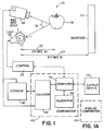
- Figure 1 is a block diagram that shows two preferred embodiments of the present apparatus. Each apparatus shown is capable of imaging an object separate from any background.
- the novel apparatus enables the imaging of an object in a scene completely segmented from the background. Therefore, the image of the object can be processed without any interference from the background image of the scene.
- various backgrounds can be added to the segmented object image to create different scenes.
- the present apparatus comprises an image input device 110 that develops an image of a scene that includes a background 135 and one or more objects 130.
- the objects are illuminated by a light source 120 that is a first distance 132 from the object 130 and a second distance 134 from the background 135.
- the light 120 is controlled by a control 125 that switches the light 120 in a manner so that the image input device 110 obtains a lighted image of the object and a dark image of the object. (See Figure 2.)
- the image can be stored in a storage device 142 and can also be fed to a comparator 145 where it is processed.
- the comparator 145 may comprise a digital device, like a computer 140, running the novel algorithm 200 (also shown in Figure 2) or may be an analog device that also performs the same algorithmic functions 200.
- the comparator 145 also triggers or is synchronized with the control 125 to obtain the lighted and dark image.
- the apparatus also optionally includes an output device 150, like a video monitor, for displaying the scene and/or processed object image.
- the video monitor 150 can also provide a user with control functions for manually operating the system.
- the image input device 110 can be a video camera, a charged coupled device (CCD) camera, a charged injection device (CID), or any other known input device for generating images.
- the image input device 110 can be sensitive to any general electromagnetic energy and includes light (either black and white, or color), infrared, and/or ultraviolet, depending upon the requirements of the application. Below these electromagnetic energy ranges will be referred to as "light” with no loss in generality intended.
- Preferred embodiment of the image input device is Sony card-camera CCB-C35YC or Sony XC-999.
- the light 120 can be any electromagnetic energy source that is dictated by the application and is compatible with the image input device. For example, if a purpose of the system is to image properties of the object that are measured using ultraviolet light, the light 120 would emit light in the ultraviolet energy spectrum and the image input device 110 would be sensitive to energy in this range.
- One or more lights can be used.
- the individual light types include flash, strobe, and/or fluorescent light. Different types of lights can be used together. For example, the different lights in the combination might emit light of different colors.
- Some preferred lights 120 include flash tubes Mouser U-4425 or two GE cool-white fluorescent bulbs (22 Watts and 30 Watts), GE FC8T9-CW and GE FC12T9-CW, respectively or equivalents.
- the light control 125 switches one or more of the lights 120 on and off, or switches the lights 120 so that they change their output intensity level.
- the control 125 can be triggered by any means that is known in the art, e.g., a separate light controller, a fixed interval timer (like a strobe light controller), a circuit that responds to the vertical sync pulse of a video signal, or a manual switch.
- One preferred light control 125 trigger is a digital output that is provided by the comparator 145, in particular the computer 140.
- the control may be synchronized with functions in the video input device 110 or the comparator 145 (computer 140) or both.
- the object 130 can be any object that is to be imaged; that is, any object capable of reflecting electromagnetic energy back to the image input device 110. Examples would include produce at a supermarket checkout, bulk items (like hardware or packaged goods) on a conveyer, and actors or objects on a stage or movie set.
- One novel feature of the present invention is the distance relationships between the light 120 and the object 130 and the background 135.
- the first distance 132 between the light 120 and the object 130 is short so that the light 120 illuminates the object 130 much more strongly than the background 135.
- the second distance 134 between the light 120 and the background 135 is larger so that the light 120 illuminates the background 135 very weakly.
- This difference in illumination enables the invention 100 to separate or segment the object 130 from the background 135.
- the required relative difference in illumination of the object and background depends on their relative reflectivities. Let Ro denote what percentage of the incident light is reflected by the object. Similarly, let Rb denote the reflectance of the background. Further, let the object distance 132 be called Do and the background distance 134 be called Db. For the separation procedure to work it must be the case that: Ro/Do2 > Rb/Db2 .
- Angle 136 is the angle between a ray from the light 120 to the object 130 and another ray from the object 130 to the camera 110. This angle 136 should be small so that the entire part of the object 130 imaged by the image input device 110 is illuminated by the light 120. This angle must generally be less than 90 degrees. A more preferred angle is between 0 and 15 degrees. The most preferred angle is close to zero. One way to achieve an angle 136 of zero degrees is to encircle the image input device 110 with the light 120. Alternatively, the object 130 can be illuminated by more than one light 120 each of which is located at a different location surrounding the image input device 110.
- the comparator 145 novelly compares two images of the scene.
- a first image that is compared is an image of the scene that is not illuminated by the light 120 or illuminated by the light 120 at a low intensity.
- a second image that is compared is an image of the scene that is illuminated by the light 120 at full or at a higher intensity.
- the difference in light intensity illuminating the two images must be enough so that the image of the object 130 appears brighter in the more illuminated image.
- the necessary light intensity difference that creates the two compared images must be great enough to permit the system 100 to distinguish the object 130 from the background 135.
- the measured change in object brightness must be more than 1%.
- the video signal is digitized to 8 bits, the measured brightness must increase by more than one count (0.39%).
- An increase on the order of 2% - 10% works well in practice. Differences greater than 10% are more preferred. These differences are enabled by establishing a tolerance T as described below (for figure 200). It should be noted that these percentages are given in terms of measured values, not true light intensities.
- the comparator 145 may be a digital device like a digital circuit 140 or any computer 140 (e.g., a personal computer, workstation, etc.) or a set of digital signal processors 140 (that implement the algorithm 200) either alone or installed in a computer. These apparatus are well know in the art.
- the digital version of the comparator 145 would also use a digitizer 143.
- the digitizer 143 is a device that digitizes the image signal from the image input device 110. Digitizers 143 and their operation with digital imaging circuits are well known in the art.
- the digitizer 143 can be located before the memory storage 142, in the computer 140 or anywhere between the video input device 110 and computer 140. If the image input device 110 is a digital camera then a separate digitizer may not be required.
- the digitizer may be separate from or may be a part of the computer 140. Note that the image may be stored in the computer 140 memory as well as in the storage device 142.
- the comparator 145 may be implemented with an analog circuit. (See Figure 1A.)
- the storage device 142 would recreate the stored image in an analog form in synchrony with the incoming video image.
- the storage device might be a short video tape loop, an analog or digital delay line, or a digitizer with memory and a suitable digital-to-analog converter.
- the analog comparator 145 would then point-wise subtract the two synchronized video signals and determine whether the difference was greater than some preset tolerance (typically a voltage). If the difference was large enough, an analog switch could be used to pass one of the two video signals. When the difference was too small, a reference black level voltage (or some other suitable indication for background areas) could be substituted in place of the original video signal.
- the system 100 can also optionally include an output device 150.
- the output device can be a video display, printer, photo-processor, image processing device, or any of the output devices 150 known in the art.
- the output device 150 can provide a user with a visual display of the object with and without the background and various processed images of the object and/or background.
- the output device 150 can also provide the user with control functions by which the user can display alternative images, operate the system 100, or reconfigure the system 100 (e.g., changing which lights 120 or light levels are used).
- the output of the system 100 might also form the input for some further stage of processing such as recognition of the extracted foreground object 130.
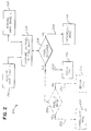
- Figure 2 is a flow chart showing the steps of a preferred method 200 (also shown in Figure 1) that is performed by the comparator 145.
- the comparator 145 embodied as a computer 140 the method 200 is embodied as a software algorithm.
- step 210 an image (a first image) of the scene is produced with the light 120 switched on or at a higher intensity so as to illuminate object 130 properly.
- Control 125 controls the light 120 switching.
- step 220 a second image of the scene is produced with the light 120 switched off or set to a level below the level in step 210.
- the setting of the light 120 should be such that the object 130 appears darker in the second image than in the first image.
- the object 130, the background 135, and the image input device 110 should be at the same position in both step 210 and 220 to assure that the first and second images are in spatial registration.
- each pixel is numbered starting in the upper left corner of the image then proceeding across the first line then down to the second line in the manner of reading a book.
- Registration means that each numbered pixel in the first image corresponds to the same area of the scene as the identically numbered pixel in the second image. Proper registration can be ensured by either acquiring the first and second image in quick succession, or by imaging a stationary object 130 against a stationary background 135.
- step 220 can be performed before step 210.
- step 230 of the algorithm 200 performed by the digital comparator 145 the first and second images are digitized in the digitizer 143.
- each and every pixel in the first digitized image is compared to the respective pixel at the same location in the second digitized image.
- Pixel by pixel comparisons such as this are known in the image processing art. For example, although the pixels in each pair being compared must correspond to one another (i.e., be in the same respective location in each image), the corresponding pixel pairs in the images can be compared in any order. Further every second or third pixel might be compared.
- step 240 a check is performed on a pixel by pixel basis to determine if a pixel in the first image is brighter than the corresponding pixel in the second image by more than a value T.
- the algorithm 200 takes the branch 242 and designates this pixel as corresponding to the object 130.
- the algorithm 200 takes the branch 244 and designates this pixel as corresponding to the background 135.
- the value of tolerance T may be a constant.
- a preferred tolerance T is 5% of the largest image intensity.
- the value of T may vary depending on the positions of pixels in the image or depending on the intensity of the pixel in the dark image.
- the positional variation of T allows the system to compensate for uneven illumination from source 120.
- the dark intensity variation of T allows the system to correctly identify foreground objects with low reflectivities (such as black objects).
- the value T may be fixed or may be recomputed from time to time by the system. It might, for instance, be necessary to change the value of T as light source 120 ages or changes in intensity for some other reason (such as a variation in the AC line voltage supplied to the bulb).
- This recomputation could be performed on a pair of images of the background with no object (one image of the background 135 highly illuminated and one less so). Since no object is present, both background images should appear to be illuminated the same amount (with ambient light). However, in practice, the light 120 might illuminate the background 135 slightly when the light is switched to a higher intensity. Therefore a tolerance T is chosen for the comparison of the corresponding pixel pairs. The tolerance T could then be set so that only a very small number of pixels in this pair of background images actually passes the test. For example, in a preferred embodiment, T would be set so that fewer than 10% of the pixel pairs differ in illumination more than the tolerance T.
- the method for performing steps 230 and 240 using an analog comparator is similar to that described for digital computer 140 above.
- the first image is stored in the storage device 142. By use of a delay, the stored first image is presented in synchrony with the incoming second image.
- the analog comparator 145 then point-wise subtracts the two synchronized image signals and determines whether the difference was greater than tolerance T, typically enabled as a voltage. If the difference was larger than T, an analog switch is used to pass one of the two video signals. When the difference is smaller than T, a reference black level voltage (or some other suitable indication for background areas) is substituted in place of the original video signal.
- the steps 230 and 240 are performed on a pixel by pixel basis for each pixel location in the scene image.
- the result is that the pixels corresponding to the object 130 are collected in a segmented object image 250.
- the segmented object image all pixels from the first image that are substantially brighter than their corresponding pixel in the second image are collected in segmented object image at the position they were in the first image. Therefore, the segmented object image corresponds to the desired image of the object 130 removed from the background 135. If needed, the remaining pixels in the image (e.g., the pixels not corresponding to the object 130) can be assigned any desired value and/or can be further processed using known image processing techniques.
- the pixels corresponding the background 135 are collected in a segmented background image 260. Specifically, all pixels from the first image that are not substantially brighter than the corresponding pixel in the second image are collected in the segmented background image at the position they were in the first image. (In a preferred embodiment, "substantially brighter” means that the difference in illumination between the pixels in the corresponding pixel pair is greater than the tolerance, T.)
- the segmented background image corresponds to the image of the background 135 with the object 130 removed. If needed, the remaining pixels in the segmented background image (i.e., those corresponding to the removed object pixel locations) can be assigned any desired value and/or further processed using known image processing techniques.
- steps 244 and 260 need not be performed. Similarly, if only the image of the background 135 is desired, steps 242 and 250 need not be performed.
- a translucent part of the object 130 may be separated from an opaque part of the object 130, by adding steps 252, 254, and 256.
- step 242 goes to step 252 instead of step 250.
- Step 252 determines if the object 130 pixels of the second image (the object 130 under low illumination) are brighter than a value V, a second tolerance value. If so, branch 253 is taken and the object pixel belongs to the translucent part 254 of object 130. (The object is translucent at this pixel location since some ambient light passed through the object 130 and was imaged at this location when the light 120 was switched to low illumination.) If not, then branch 255 is taken and the pixel belongs to opaque part 256 of object 130.
- the value V may be constant for each pixel in the second image or may be variable, depending, for example, on the position on the pixel in the second image. Note that the value, V, may further be computed as describe above, from an image of the background 135 alone, by choosing a V such that 95% to 85% of the background image is brighter than V. A preferred value for V is 20% of the brightest image intensity.
- a translucent object image is created.
- each pixel in the first image which corresponds to a pixel in the second image that is brighter than the value V, corresponds a translucent part of object 130 and is stored in a translucent object image.
- the translucent object image will contain only the image of the translucent parts of object 130. If needed, the remaining pixels of the translucent object image may be assigned any desired value and/or processed further.
- step 256 an opaque object image is created.
- each pixel in the first image (which belongs to the object) which corresponds to a pixel in the second image equal to or darker than the value V, corresponds to an opaque part of object 130 and is stored in the opaque object image 256.
- the opaque object image will contain only the image of the opaque parts of object 130. If needed, the remaining pixels of the opaque object image may be assigned any desired value and/or be further processed.
- step 254 need not be performed.
- step 256 need not be performed.
- step 252 is combined with step 240 and steps 242 and 250 are removed. This results in the translucent object image or the opaque object image (or both) but not the complete segmented object image 250.
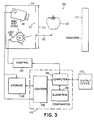
- FIG. 3 is a block diagram of another preferred embodiment 300 of the present invention.
- the apparatus 300 is an enhanced version of the apparatus 100 that is capable of imaging object 130 with a controlled light 120, in a manner such that the image of object 130 will be independent of both the background and the ambient illumination.
- the apparatus 300 uses an opaque enclosure 310 that encloses the light 120 and image input device 110.
- the enclosure has a single opening 312 facing the object 130.
- the opening 312 is of a sufficient size to allow the object 130 to be imaged by the image input device 110 and illuminated by the light 120.
- the opening can be square, round or any other shape.
- the intent is to cause enclosure 310 to cast a shadow on the front surface of object 130 (the side toward camera 110).
- there is a very short distance 332 between the opening 312 and the object 130 This distance is very short to ensure that the part of the object 130 viewed by the image input device 110 through the opening 312 is illuminated almost exclusively by the light 120. This distance could be zero, i.e.
- the opening 312 could be covered by a structural element (see 430 in Figure 4) like a wire mesh, that acts as a support for the object 130 and maintains the object 130 at or near a zero distance 332 from the opening 312.
- the apparatus 300 is useful for applications where it is desired to image an object with a controlled spectral distribution of light. For example, if specific measurements are needed to be made of the color of object 130, then it may be required to image object 130 with a specific light as the imaged color of an object is dependent on the incident light. If the object 130 is imaged with the apparatus shown in figure 3, then the colors measured from the image will not change with changing background or ambient illumination.
- One application of this apparatus 300 is in the identification of produce. This use is disclosed in U.S. Patent Application number xxxx to Bolle et al. entitled "Produce Identification System" which is herein incorporated by reference.
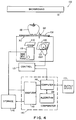
- FIG 4 is a block diagram of a system 400 that shows further enhancements to the apparatus 300 of Figure 3.
- the apparatus 400 allows the object 130 to be placed on top of the opening 312 on a transparent support surface 430 (such as a sheet of glass).
- Surface 430 provides a support for the object 130 and also ensures a suitably close and repeatable distance 332.
- the apparatus 400 allows imaging of shiny objects by reducing the glare (specular reflections) from the image.
- the apparatus accomplishes this by fitting a linear polarization filter 410 to the image input device 110. This is done to ensure that all the light entering image input device 110 first passes through polarizing filter 410.
- a second linear polarization filter 420 is associated with light 120.
- filter 420 must be situated between the light 120 and the opening 312 in a manner insure that the majority of the light reaching the object 130 is polarized.
- the direction of the polarization in the filter 420 is exactly orthogonal to the direction of polarization in filter 410.
Landscapes
- Engineering & Computer Science (AREA)
- Physics & Mathematics (AREA)
- General Physics & Mathematics (AREA)
- Theoretical Computer Science (AREA)
- Multimedia (AREA)
- Signal Processing (AREA)
- Computer Vision & Pattern Recognition (AREA)
- Image Processing (AREA)
- Image Analysis (AREA)
Applications Claiming Priority (2)
| Application Number | Priority Date | Filing Date | Title |
|---|---|---|---|
| US235064 | 1981-02-17 | ||
| US08/235,064 US5631976A (en) | 1994-04-29 | 1994-04-29 | Object imaging system |
Publications (1)
| Publication Number | Publication Date |
|---|---|
| EP0680205A2 true EP0680205A2 (de) | 1995-11-02 |
Family
ID=22883955
Family Applications (1)
| Application Number | Title | Priority Date | Filing Date |
|---|---|---|---|
| EP95101352A Withdrawn EP0680205A2 (de) | 1994-04-29 | 1995-02-01 | Abbildungssystem zur Objektsegmentierung |
Country Status (3)
| Country | Link |
|---|---|
| US (1) | US5631976A (de) |
| EP (1) | EP0680205A2 (de) |
| JP (1) | JPH07302339A (de) |
Cited By (9)
| Publication number | Priority date | Publication date | Assignee | Title |
|---|---|---|---|---|
| WO1997027702A1 (en) * | 1996-01-25 | 1997-07-31 | Polaroid Corporation | Method for replacing the background of an image |
| EP0866369A1 (de) * | 1997-03-17 | 1998-09-23 | Eastman Kodak Company | Negatives Bild erzeugendes farbphotographisches Silberhalogenidmaterial und Verfahren |
| WO1999038121A1 (en) * | 1998-01-27 | 1999-07-29 | Sensar, Inc. | Method and apparatus for removal of bright or dark spots by the fusion of multiple images |
| US6069696A (en) * | 1995-06-08 | 2000-05-30 | Psc Scanning, Inc. | Object recognition system and method |
| DE19941644A1 (de) * | 1999-08-27 | 2001-03-01 | Deutsche Telekom Ag | Verfahren zur echtzeitfähigen Segmentierung von Videoobjekten bei bekanntem stationären Bildhintergrund |
| EP1215619A1 (de) * | 2000-12-16 | 2002-06-19 | Bayerische Motoren Werke Aktiengesellschaft | Verfahren zur Überwachung des Innenraums eines Kraftfahrzeuges |
| WO2006129316A1 (en) * | 2005-05-31 | 2006-12-07 | Zamir Recognition Systems Ltd. | Light sensitive system and method for attenuating the effect of ambient light |
| EP1722552A3 (de) * | 2005-05-11 | 2007-05-09 | Delphi Technologies, Inc. | Verfahren zum Betrieb eines visuellen Insassenerfassungssystems |
| DE102006044365A1 (de) * | 2006-09-20 | 2008-04-03 | Mettler-Toledo (Albstadt) Gmbh | Automatische Erkennungsvorrichtung |
Families Citing this family (79)
| Publication number | Priority date | Publication date | Assignee | Title |
|---|---|---|---|---|
| WO1997016926A1 (en) * | 1995-10-31 | 1997-05-09 | Sarnoff Corporation | Method and apparatus for determining ambient conditions from an image sequence |
| GB2337327B (en) * | 1997-02-18 | 2000-11-15 | Raymond Charles Johnson | Apparatus and method for monitoring hand washing |
| JP4244391B2 (ja) * | 1997-04-04 | 2009-03-25 | ソニー株式会社 | 画像変換装置及び画像変換方法 |
| US6349113B1 (en) * | 1997-11-03 | 2002-02-19 | At&T Corp. | Method for detecting moving cast shadows object segmentation |
| EP1717684A3 (de) | 1998-01-26 | 2008-01-23 | Fingerworks, Inc. | Verfahren und Vorrichtung zur Integration von manuellen Eingaben |
| US20040114035A1 (en) * | 1998-03-24 | 2004-06-17 | Timothy White | Focusing panel illumination method and apparatus |
| KR100367831B1 (ko) * | 1998-06-30 | 2003-01-10 | 주식회사 팬택앤큐리텔 | 영상의 색차신호 필터링 방법 및 장치 |
| SE9802923L (sv) * | 1998-08-31 | 2000-03-01 | Alfa Laval Agri Ab | Förfarande och anordning för lokalisering av ett djurs spenar |
| US6674485B2 (en) * | 1998-08-31 | 2004-01-06 | Hitachi Software Engineering Co., Ltd. | Apparatus and method for image compositing |
| US6363366B1 (en) * | 1998-08-31 | 2002-03-26 | David L. Henty | Produce identification and pricing system for checkouts |
| SE9802919L (sv) * | 1998-08-31 | 2000-03-01 | Alfa Laval Agri Ab | Anordning och förfarande för övervakning av ett djurrelaterat område |
| AU5419600A (en) * | 1999-06-21 | 2001-01-09 | Yissum Research Development Company Of The Hebrew University Of Jerusalem | System and method for differentiating between image foreground and background in an image based on an invisible keying signal |
| US6636626B1 (en) * | 1999-11-30 | 2003-10-21 | Wafermasters, Inc. | Wafer mapping apparatus and method |
| US6542180B1 (en) * | 2000-01-07 | 2003-04-01 | Mitutoyo Corporation | Systems and methods for adjusting lighting of a part based on a plurality of selected regions of an image of the part |
| SE0000153L (sv) * | 2000-01-19 | 2001-07-20 | Delaval Holding Ab | En metod och en apparat för att lokalisera spenarna hos ett mjölkdjur |
| US6850872B1 (en) * | 2000-08-30 | 2005-02-01 | Microsoft Corporation | Facial image processing methods and systems |
| GB2366862B (en) * | 2000-09-14 | 2004-09-22 | Autoliv Dev | Improvements in or relating to a camera arrangement |
| US6668078B1 (en) | 2000-09-29 | 2003-12-23 | International Business Machines Corporation | System and method for segmentation of images of objects that are occluded by a semi-transparent material |
| US8042740B2 (en) * | 2000-11-24 | 2011-10-25 | Metrologic Instruments, Inc. | Method of reading bar code symbols on objects at a point-of-sale station by passing said objects through a complex of stationary coplanar illumination and imaging planes projected into a 3D imaging volume |
| WO2002046796A1 (fr) | 2000-12-06 | 2002-06-13 | Poseidon | Procede, systeme et dispositif pour detecter un corps a proximite d'une interface de type eau/air |
| SE518050C2 (sv) * | 2000-12-22 | 2002-08-20 | Afsenius Sven Aake | Kamera som kombinerar skarpt fokuserade delar från olika exponeringar till en slutbild |
| JP2002341406A (ja) * | 2001-05-11 | 2002-11-27 | Matsushita Electric Ind Co Ltd | 認証対象撮像方法及びその装置 |
| AU2003278710A1 (en) * | 2002-08-15 | 2004-03-03 | Lc Technologies, Inc. | Motion clutter suppression for image-subtracting cameras |
| DE60325536D1 (de) * | 2002-09-20 | 2009-02-12 | Nippon Telegraph & Telephone | Vorrichtung zum Erzeugen eines pseudo-dreidimensionalen Bildes |
| US7841533B2 (en) | 2003-11-13 | 2010-11-30 | Metrologic Instruments, Inc. | Method of capturing and processing digital images of an object within the field of view (FOV) of a hand-supportable digitial image capture and processing system |
| US20050122422A1 (en) * | 2003-12-08 | 2005-06-09 | Kent Edward M. | Video camera synchronized infrared strobe inspection system |
| US20080162213A1 (en) * | 2004-06-14 | 2008-07-03 | Clayton James D | Decision object for associating a plurality of business plans |
| JP4689662B2 (ja) * | 2005-03-10 | 2011-05-25 | 富士フイルム株式会社 | 撮影システム |
| US7760962B2 (en) * | 2005-03-30 | 2010-07-20 | Casio Computer Co., Ltd. | Image capture apparatus which synthesizes a plurality of images obtained by shooting a subject from different directions, to produce an image in which the influence of glare from a light is reduced |
| US8478386B2 (en) | 2006-01-10 | 2013-07-02 | Accuvein Inc. | Practitioner-mounted micro vein enhancer |
| US12089951B2 (en) | 2006-01-10 | 2024-09-17 | AccuVeiw, Inc. | Scanned laser vein contrast enhancer with scanning correlated to target distance |
| US9854977B2 (en) | 2006-01-10 | 2018-01-02 | Accuvein, Inc. | Scanned laser vein contrast enhancer using a single laser, and modulation circuitry |
| US11278240B2 (en) | 2006-01-10 | 2022-03-22 | Accuvein, Inc. | Trigger-actuated laser vein contrast enhancer |
| US8838210B2 (en) * | 2006-06-29 | 2014-09-16 | AccuView, Inc. | Scanned laser vein contrast enhancer using a single laser |
| US8255040B2 (en) | 2006-06-29 | 2012-08-28 | Accuvein, Llc | Micro vein enhancer |
| US9492117B2 (en) | 2006-01-10 | 2016-11-15 | Accuvein, Inc. | Practitioner-mounted micro vein enhancer |
| US10813588B2 (en) | 2006-01-10 | 2020-10-27 | Accuvein, Inc. | Micro vein enhancer |
| US8489178B2 (en) | 2006-06-29 | 2013-07-16 | Accuvein Inc. | Enhanced laser vein contrast enhancer with projection of analyzed vein data |
| US11253198B2 (en) | 2006-01-10 | 2022-02-22 | Accuvein, Inc. | Stand-mounted scanned laser vein contrast enhancer |
| US10238294B2 (en) | 2006-06-29 | 2019-03-26 | Accuvein, Inc. | Scanned laser vein contrast enhancer using one laser |
| US8730321B2 (en) | 2007-06-28 | 2014-05-20 | Accuvein, Inc. | Automatic alignment of a contrast enhancement system |
| US8594770B2 (en) | 2006-06-29 | 2013-11-26 | Accuvein, Inc. | Multispectral detection and presentation of an object's characteristics |
| US8244333B2 (en) * | 2006-06-29 | 2012-08-14 | Accuvein, Llc | Scanned laser vein contrast enhancer |
| US20160296146A9 (en) * | 2006-06-29 | 2016-10-13 | Fred Wood | Apparatus-Mounted Vein Contrast Enchancer |
| US8463364B2 (en) * | 2009-07-22 | 2013-06-11 | Accuvein Inc. | Vein scanner |
| US8665507B2 (en) * | 2006-06-29 | 2014-03-04 | Accuvein, Inc. | Module mounting mirror endoscopy |
| WO2008059627A1 (fr) * | 2006-11-14 | 2008-05-22 | Fujitsu Limited | Dispositif de commande d'éclairage, procédé de commande d'éclairage et appareil d'imagerie |
| US8269727B2 (en) | 2007-01-03 | 2012-09-18 | Apple Inc. | Irregular input identification |
| US8130203B2 (en) | 2007-01-03 | 2012-03-06 | Apple Inc. | Multi-touch input discrimination |
| US7855718B2 (en) | 2007-01-03 | 2010-12-21 | Apple Inc. | Multi-touch input discrimination |
| US7834894B2 (en) * | 2007-04-03 | 2010-11-16 | Lifetouch Inc. | Method and apparatus for background replacement in still photographs |
| US8794524B2 (en) * | 2007-05-31 | 2014-08-05 | Toshiba Global Commerce Solutions Holdings Corporation | Smart scanning system |
| US7988045B2 (en) * | 2007-05-31 | 2011-08-02 | International Business Machines Corporation | Portable device-based shopping checkout |
| US8544736B2 (en) | 2007-07-24 | 2013-10-01 | International Business Machines Corporation | Item scanning system |
| US20090026270A1 (en) * | 2007-07-24 | 2009-01-29 | Connell Ii Jonathan H | Secure checkout system |
| US8746557B2 (en) | 2008-02-26 | 2014-06-10 | Toshiba Global Commerce Solutions Holding Corporation | Secure self-checkout |
| US8280763B2 (en) * | 2008-02-26 | 2012-10-02 | Connell Ii Jonathan H | Customer rewarding |
| US8061603B2 (en) * | 2008-03-20 | 2011-11-22 | International Business Machines Corporation | Controlling shopper checkout throughput |
| US7889068B2 (en) * | 2008-03-20 | 2011-02-15 | International Business Machines Corporation | Alarm solution for securing shopping checkout |
| US8229158B2 (en) * | 2008-04-29 | 2012-07-24 | International Business Machines Corporation | Method, system, and program product for determining a state of a shopping receptacle |
| US20090272801A1 (en) * | 2008-04-30 | 2009-11-05 | Connell Ii Jonathan H | Deterring checkout fraud |
| CN101610623B (zh) * | 2008-06-20 | 2012-11-21 | 鸿富锦精密工业(深圳)有限公司 | 轮廓光调节方法及其计算机系统 |
| TWI427262B (zh) * | 2008-07-04 | 2014-02-21 | Hon Hai Prec Ind Co Ltd | 輪廓光調節方法及其電腦系統 |
| US20100053329A1 (en) * | 2008-08-27 | 2010-03-04 | Flickner Myron D | Exit security |
| US8704821B2 (en) * | 2008-09-18 | 2014-04-22 | International Business Machines Corporation | System and method for managing virtual world environments based upon existing physical environments |
| US8295635B2 (en) * | 2008-11-06 | 2012-10-23 | Bausch & Lomb Incorporated | Methods and apparatus for facilitating elimination of ambient light from an image |
| US9047742B2 (en) * | 2009-05-07 | 2015-06-02 | International Business Machines Corporation | Visual security for point of sale terminals |
| US9061109B2 (en) | 2009-07-22 | 2015-06-23 | Accuvein, Inc. | Vein scanner with user interface |
| HUP1000523A2 (en) * | 2010-09-27 | 2012-06-28 | Budapesti Mueszaki Es Gazdasagtudomanyi Egyetem | Method and apparatus for hand disinfection quality control |
| JP5579202B2 (ja) * | 2012-01-16 | 2014-08-27 | 東芝テック株式会社 | 情報処理装置、店舗システム及びプログラム |
| US9072426B2 (en) | 2012-08-02 | 2015-07-07 | AccuVein, Inc | Device for detecting and illuminating vasculature using an FPGA |
| JP5936993B2 (ja) | 2012-11-08 | 2016-06-22 | 東芝テック株式会社 | 商品認識装置及び商品認識プログラム |
| US10376147B2 (en) | 2012-12-05 | 2019-08-13 | AccuVeiw, Inc. | System and method for multi-color laser imaging and ablation of cancer cells using fluorescence |
| JP6195449B2 (ja) * | 2013-01-30 | 2017-09-13 | セコム株式会社 | 撮影システム |
| DE102015010919A1 (de) * | 2015-08-20 | 2017-02-23 | Diehl Bgt Defence Gmbh & Co. Kg | Verfahren zum Bestimmen einer Ausrichtung eines Objekts |
| US10650368B2 (en) * | 2016-01-15 | 2020-05-12 | Ncr Corporation | Pick list optimization method |
| US10607316B2 (en) * | 2016-07-22 | 2020-03-31 | Panasonic Intellectual Property Management Co., Ltd. | Image generating apparatus and image generating method |
| US10366379B2 (en) * | 2017-01-30 | 2019-07-30 | Ncr Corporation | Remote weigh station with delayed fraud intervention |
| US20200394804A1 (en) | 2019-06-17 | 2020-12-17 | Guard, Inc. | Analysis and deep learning modeling of sensor-based object detection data in bounded aquatic environments |
Family Cites Families (7)
| Publication number | Priority date | Publication date | Assignee | Title |
|---|---|---|---|---|
| US4314281A (en) * | 1979-10-12 | 1982-02-02 | Xerox Corporation | Shading compensation for scanning apparatus |
| US4861973A (en) * | 1987-06-18 | 1989-08-29 | Spectra-Physics, Inc. | Optical scan pattern generating arrangement for a laser scanner |
| US5091963A (en) * | 1988-05-02 | 1992-02-25 | The Standard Oil Company | Method and apparatus for inspecting surfaces for contrast variations |
| US5058178A (en) * | 1989-12-21 | 1991-10-15 | At&T Bell Laboratories | Method and apparatus for inspection of specular, three-dimensional features |
| US5115122A (en) * | 1990-12-12 | 1992-05-19 | Ncr Corporation | Compact optical scanning system |
| US5224141A (en) * | 1991-02-06 | 1993-06-29 | General Electric Company | Fluoroscopic method with reduced x-ray dosage |
| US5220614A (en) * | 1991-02-22 | 1993-06-15 | Professional Coin Grading Service, Inc. | Automated coin grading system |
-
1994
- 1994-04-29 US US08/235,064 patent/US5631976A/en not_active Expired - Lifetime
-
1995
- 1995-02-01 EP EP95101352A patent/EP0680205A2/de not_active Withdrawn
- 1995-02-10 JP JP7022774A patent/JPH07302339A/ja active Pending
Cited By (13)
| Publication number | Priority date | Publication date | Assignee | Title |
|---|---|---|---|---|
| US6069696A (en) * | 1995-06-08 | 2000-05-30 | Psc Scanning, Inc. | Object recognition system and method |
| WO1997027702A1 (en) * | 1996-01-25 | 1997-07-31 | Polaroid Corporation | Method for replacing the background of an image |
| EP0866369A1 (de) * | 1997-03-17 | 1998-09-23 | Eastman Kodak Company | Negatives Bild erzeugendes farbphotographisches Silberhalogenidmaterial und Verfahren |
| US5939246A (en) * | 1997-03-17 | 1999-08-17 | Eastman Kodak Company | Color photographic silver halide negative imaging material and process |
| WO1999038121A1 (en) * | 1998-01-27 | 1999-07-29 | Sensar, Inc. | Method and apparatus for removal of bright or dark spots by the fusion of multiple images |
| US6088470A (en) * | 1998-01-27 | 2000-07-11 | Sensar, Inc. | Method and apparatus for removal of bright or dark spots by the fusion of multiple images |
| DE19941644A1 (de) * | 1999-08-27 | 2001-03-01 | Deutsche Telekom Ag | Verfahren zur echtzeitfähigen Segmentierung von Videoobjekten bei bekanntem stationären Bildhintergrund |
| EP1215619A1 (de) * | 2000-12-16 | 2002-06-19 | Bayerische Motoren Werke Aktiengesellschaft | Verfahren zur Überwachung des Innenraums eines Kraftfahrzeuges |
| US6674079B2 (en) | 2000-12-16 | 2004-01-06 | Bayerische Motoren Werke Aktiengesellschaft | Method and apparatus for monitoring the interior space of a motor vehicle |
| EP1722552A3 (de) * | 2005-05-11 | 2007-05-09 | Delphi Technologies, Inc. | Verfahren zum Betrieb eines visuellen Insassenerfassungssystems |
| US7791670B2 (en) | 2005-05-11 | 2010-09-07 | Delphi Technologies, Inc. | Method of operation for a vision-based occupant sensing system |
| WO2006129316A1 (en) * | 2005-05-31 | 2006-12-07 | Zamir Recognition Systems Ltd. | Light sensitive system and method for attenuating the effect of ambient light |
| DE102006044365A1 (de) * | 2006-09-20 | 2008-04-03 | Mettler-Toledo (Albstadt) Gmbh | Automatische Erkennungsvorrichtung |
Also Published As
| Publication number | Publication date |
|---|---|
| JPH07302339A (ja) | 1995-11-14 |
| US5631976A (en) | 1997-05-20 |
Similar Documents
| Publication | Publication Date | Title |
|---|---|---|
| US5631976A (en) | Object imaging system | |
| US6668078B1 (en) | System and method for segmentation of images of objects that are occluded by a semi-transparent material | |
| Madden | Extended intensity range imaging | |
| CA2438724A1 (en) | Method and apparatus for inhibiting projection of selected areas of a projected image | |
| EP1433139B1 (de) | Vorrichtung und verfahren zur digitalisierung eines objektes | |
| WO1998039627A3 (en) | Calibration of imaging systems | |
| US20140210964A1 (en) | Object distance determination from image | |
| EP0732579A3 (de) | Verfahren zum Erkennen und Beurteilen von Fehlern in semi-reflektierender Oberflächenschicht | |
| CN110677949A (zh) | 灯具的控制方法和控制系统以及电子设备 | |
| US20020089599A1 (en) | Illumination and image acquisition system | |
| CN212845064U (zh) | 一种图纹照明检测系统 | |
| US11589444B2 (en) | Apparatuses and methods for illuminating objects | |
| JPH04343047A (ja) | 異物検査方法 | |
| JPH08105722A (ja) | デバイス外観検査用照明器及びこの照明器を用いたデバイス外観自動検査装置 | |
| US20230224428A1 (en) | Information processing device, composite video generation method, and program | |
| JPH09282444A (ja) | 視覚認識装置 | |
| JP3724659B2 (ja) | 画像処理装置 | |
| KR970059986A (ko) | 명암 정보를 이용한 물체의 3차원 형상 추출 장치 및 방법 | |
| JP2002374445A (ja) | 電子カメラ | |
| JP2000205841A (ja) | ウエハ形状認識方法 | |
| KR20220056291A (ko) | 로봇을 이용한 비전검사장치 | |
| WO2022185078A1 (en) | Video capture | |
| JP2001208692A (ja) | 照明制御方法 | |
| JPH06289461A (ja) | 撮影用照明装置 | |
| JPH08271985A (ja) | 照明装置 |
Legal Events
| Date | Code | Title | Description |
|---|---|---|---|
| PUAI | Public reference made under article 153(3) epc to a published international application that has entered the european phase |
Free format text: ORIGINAL CODE: 0009012 |
|
| AK | Designated contracting states |
Kind code of ref document: A2 Designated state(s): DE FR GB |
|
| STAA | Information on the status of an ep patent application or granted ep patent |
Free format text: STATUS: THE APPLICATION HAS BEEN WITHDRAWN |
|
| 18W | Application withdrawn |
Withdrawal date: 19960718 |