EP0680062B1 - Lastwähler - Google Patents
Lastwähler Download PDFInfo
- Publication number
- EP0680062B1 EP0680062B1 EP95102084A EP95102084A EP0680062B1 EP 0680062 B1 EP0680062 B1 EP 0680062B1 EP 95102084 A EP95102084 A EP 95102084A EP 95102084 A EP95102084 A EP 95102084A EP 0680062 B1 EP0680062 B1 EP 0680062B1
- Authority
- EP
- European Patent Office
- Prior art keywords
- clamping ring
- switch
- contact
- switch shaft
- contact carrier
- Prior art date
- Legal status (The legal status is an assumption and is not a legal conclusion. Google has not performed a legal analysis and makes no representation as to the accuracy of the status listed.)
- Expired - Lifetime
Links
- 239000000969 carrier Substances 0.000 claims abstract description 9
- 238000012216 screening Methods 0.000 claims 1
- 239000011810 insulating material Substances 0.000 description 3
- 238000004804 winding Methods 0.000 description 3
- 230000000149 penetrating effect Effects 0.000 description 2
- 238000011161 development Methods 0.000 description 1
- 230000018109 developmental process Effects 0.000 description 1
- 239000003365 glass fiber Substances 0.000 description 1
- 239000011347 resin Substances 0.000 description 1
- 229920005989 resin Polymers 0.000 description 1
- 239000007787 solid Substances 0.000 description 1
Images
Classifications
-
- H—ELECTRICITY
- H01—ELECTRIC ELEMENTS
- H01H—ELECTRIC SWITCHES; RELAYS; SELECTORS; EMERGENCY PROTECTIVE DEVICES
- H01H9/00—Details of switching devices, not covered by groups H01H1/00 - H01H7/00
- H01H9/0005—Tap change devices
- H01H9/0016—Contact arrangements for tap changers
Definitions
- the invention relates to a load selector for step transformers.
- load selectors With load selectors, an uninterrupted load changeover is carried out under voltage between adjacent taps of a control winding of a step transformer.
- the load selector simultaneously fulfills the function of a tap selector, which selects the new winding tap to be connected, and a load switch, which, with brief interposition of one or more contact resistors, switches the current from the original tap to the new tap without interruption.
- load selector essentially consist of an oil vessel formed by an insulating material cylinder, the upper end of which is closed at the load selector head and the lower end of which is sealed by the oil vessel bottom, and the tap changer insert located therein.
- the fixed contacts of the load selector are arranged in separate planes and led out to the outside with connection contacts.
- the tap changer insert contains the entire movable contact system and consists of a centrally mounted control shaft, load selector switch elements and, if necessary, a preselector contact carrier.
- the entire, movable contact system consists of individual contact carriers arranged one above the other, each of which is attached to the selector shaft in the same horizontal planes as the associated fixed contacts.
- the contact carriers in turn each have a switch contact and one or more auxiliary switch contacts arranged laterally therefrom. So far, the contact carriers have been screwed directly to the control shaft, which is usually designed as hard paper or glass fiber reinforced cast resin tube, by means of these penetrating screws.
- the object of the invention is to provide an improved load selector that is simple and uncomplicated fastening of the contact systems on the one hand and other components of the load selector, such as B. switching resistors, shield rings or the like on the other hand on the selector shaft allowed.
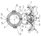
- the figure shows a load selector according to the invention in a schematic horizontal sectional view.
- the load selector has, as is generally the case, within an oil vessel formed by an insulating material cylinder 1 and bottom and head parts, not shown, a vertically penetrating switching shaft 4, which has one or more horizontally attached contact carriers 5.
- the control shaft 4 can be rotated by means of known drive means, also not shown, such that fixed contacts 2 of each of the contact carriers 5, each arranged in the same horizontal plane on the inside of the insulating material cylinder 1, lead to the winding leads of the connected step transformer via outward leads 3 are connected, can be connected.
- Each contact carrier 5 has a switching contact 6 designed as a roller contact and two auxiliary switching contacts 7, 8, also roller contacts, arranged on both sides thereof. The electrical connection to the individual contacts and the load transfer are not shown in detail.
- Each contact carrier 5 is fastened to the selector shaft 4 by a two-part clamping ring 9.
- the clamping ring 9 is clamped on the selector shaft 4 by fastening means 10, 11, screws, for example. It is also possible, instead of fastening means 10, 11 on both sides, as shown in the figure, to use only a single screw or the like for bracing and to provide a latching connection, a hinge or the like on the opposite side. It is also possible both to fasten the contact carrier 5 separately on part of the clamping ring 9 and also to design the contact carrier 5 itself - as shown in the figure - as an integral part of a part of the clamping ring 9.
- the clamping ring 9 has one or more flanges on its outer circumference 14 on, on which or - for example by means of provided threaded holes 15 - other components on the clamping ring 9 and thus their rotational movement, on the Switch shaft 4 are arranged.
- This can e.g. B. switching resistors, shield rings or similar Components of the load selector.
- a centering aid on the outer surface of the selector shaft 4 provided that corresponds to the clamping ring 9 and a clear location assignment of the Contact carrier 5 and at the same time an additional protection against rotation is guaranteed.
- a blind bore 13 is provided in the selector shaft 4, in which a centering pin 12 is attached, which in turn in a recess 16 in the inner surface facing the selector shaft 4 of the clamping ring 9 engages.
- the clamping ring 9 is advantageously designed so that its facing the selector shaft 4 Adapts the inner surface essentially in its curvature to the outer contour of the selector shaft.
Landscapes
- Driving Mechanisms And Operating Circuits Of Arc-Extinguishing High-Tension Switches (AREA)
- Housings And Mounting Of Transformers (AREA)
- Discharge Heating (AREA)
- Supporting Of Heads In Record-Carrier Devices (AREA)
- Control Of Motors That Do Not Use Commutators (AREA)
- Clamps And Clips (AREA)
Description
Solche Lastwähler bestehen im wesentlichen aus einem von einem Isolierstoffzylinder gebildeten Ölgefäß, dessen oberes Ende am Lastwählerkopf und dessen unteres Ende durch den Ölgefäßboden abgeschlossen ist, und dem darin befindlichen Stufenschaltereinsatz.
An der Innenwandung des Ölgefäßes sind in voneinander getrennten Ebenen die feststehenden Kontakte des Lastwählers angeordnet und nach außen mit Anschlußkontakten herausgeführt. Der Stufenschaltereinsatz enthält das gesamte bewegliche Kontaktsystem und besteht aus einer zentrisch gelagerten Schaltwelle, Lastwähler-Schaltelementen und ggf. einem Vorwähler-Kontaktträger. Das gesamte, bewegliche Kontaktsystem besteht dabei aus übereinander angeordneten einzelnen Kontaktträgem, die jeweils in gleichen horizontalen Ebenen wie die zugehörigen feststehenden Kontakte an der Schaltwelle befestigt sind. Die Kontaktträger ihrerseits weisen jeweils einen Schaltkontakt und einen oder mehrere seitlich von diesem angeordnete Hilfsschaltkontakte auf. Bisher werden die Kontaktträger direkt mit der Schaltwelle, die üblicherweise als Hartpapier- oder als glasfaserverstärktes Gießharzrohr ausgebildet ist, mittels diese durchdringender Schrauben verschraubt.

Auch hierbei werden die Kontaktträger mit der Schaltwelle verschraubt, wobei sie zusätzlich noch teilweise in Aussparungen der Schaltwelle eingreifen.
Dies geschieht dadurch, daß beide Teile des Klemmringes die Schaltwelle umfassen und durch Schrauben miteinander auf dieser verspannt werden.
Die Unteransprüche betreffen besonders vorteilhafte Weiterbildungen der Erfindung.
Die Schaltwelle 4 ist mittels ebenfalls nicht dargestellter bekannter Antriebsmittel drehbar, derart, daß von jedem der Kontaktträger 5 jeweils in der gleichen horizontalen Ebene an der Innenseite des Isolierstoffzylinders 1 angeordnete feste Kontakte 2, die über nach außen geführte Ableitungen 3 mit den Wicklungsausleitungen des angeschlossenen Stufentransformators in Verbindung stehen, beschaltbar sind.
Jeder Kontaktträger 5 weist einen als Rollenkontakt ausgebildeten Schaltkontakt 6 und zwei beidseitig davon angeordnete Hilfsschaltkontakte 7, 8, ebenfalls Rollenkontakte, auf.
Die elektrische Verbindung zu den einzelnen Kontakten und die Lastableitung sind nicht näher dargestellt.
Jeder Kontaktträger 5 wird durch einen zweiteiligen Klemmring 9 an der Schaltwelle 4 befestigt. Der Klemmring 9 wird durch Befestigungsmittel 10, 11, Schrauben etwa, auf der Schaltwelle 4 verspannt. Es ist auch möglich, statt beidseitiger Befestigungsmittel 10, 11, wie in der Figur dargestellt, nur eine einzige Schraube o. ä. zur Verspannung zu verwenden und auf der gegenüberliegenden Seite eine Rastverbindung, ein Scharnier o. dgl. vorzusehen.
Es ist weiterhin sowohl möglich, den Kontaktträger 5 separat auf einem Teil des Klemmringes 9 zu befestigen, als auch den Kontaktträger 5 selbst - wie in der Figur dargestellt - als integralen Bestandteil eines Teiles des Klemmringes 9 auszubilden.
In beiden Fällen sind keinerlei Bohrungen in der Schaltwelle 4 erforderlich, durch die in deren Inneres ragende Befestigungsmittel eingeführt werden müßten. Vielmehr erfolgt die Befestigung des gesamten Kontaktträgers 5 ausschließlich durch außerhalb der Schaltwelle 4 - vorzugsweise horizontal - sich erstreckende und damit frei zugängliche Befestigungsmittel 10, 11.
- 1
- -Isolierstoffzylinder
- 2
- -feste, beschaltbare Kontakte
- 3
- -Ableitungen
- 4
- -Schaltwelle
- 5
- -Kontaktträger
- 6
- -Schaltkontakt
- 7
- -Hilfsschaltkontakt
- 8
- -Hilfsschaltkontkat
- 9
- -zweiteiliger Klemmring
- 10
- -Befestigungsmittel
- 11
- -Befestigungsmittel
- 12
- -Zentrierstift
- 13
- -Sackbohrung
- 14
- -Flansch
- 15
- -Gewindebohrungen
- 16
- -Aussparung
Claims (4)
- Lastwähler für Stufentransformatoren,mit einem zylindrischen Ölgefäß (1), an dessen Innenseite feste Stufenkontakte (2) angeordnet sind, sowie einer im Inneren angeordneten Schaltwelle (4), die durch Antriebsmittel drehbar ist und an der ein Kontaktträger (5) oder übereinander in mehreren Phasen mehrere Kontaktträger (5) befestigt sind, der bzw. die wiederum mindestens einen Schaltkontakt (6) aufweisen, mittels der die festen Stufenkontakte (2) beschaltbar sind,
dadurch gekennzeichnet,daß jeder Kontaktträger (5) durch einen zweiteiligen Klemmring (9) an der Schaltwelle (4) befestigt ist, derart, daß der Kontaktträger (5) fest mit einem Teil des zweiteiligen Klemmringes (9) verbunden ist und beide Teile des Klemmringes (9) die Schaltwelle (4) umfassen und durch außerhalb der Schaltwelle (4) verlaufende Befestigungsmittel (11, 12) kraftschlüssig miteinander verspannt sindund daß der zweiteilige Klemmring (9) an seinem äußeren Umfang einen oder mehrere Flansche (14) zur Befestigung weiterer, die Drehung der Schaltwelle (4) mitvollziehender Bauteile, wie z. B. Überschaltwiderstände oder Abschirmringe, aufweist. - Lastwähler nach Anspruch 1,
dadurch gekennzeichnet,daß der Kontaktträger (5) als integraler Bestandteil eines Teiles des zweiteiligen Klemmringes (9) ausgebildet ist. - Lastwähler nach Anspruch 1 oder 2,
dadurch gekennzeichnet,daß die Innenfläche des zweiteiligen Klemmringes (9) im wesentlichen der Oberfläche der Schaltwelle (4) in ihrer Krümmung angepaßt ist. - Lastwähler nach einem der Ansprüche 1 bis 3,
dadurch gekennzeichnet,daß an der Außenfläche der Schaltwelle (4) mindestens eine Zentrierhilfe (12) vorgesehen ist, die mit einer Kontur an der Innenfläche des zweiteiligen Klemmringes (9) korrespondiert, derart, daß eine eindeutige Lagezuordnung und Verdrehsicherung gewährleistet ist.
Applications Claiming Priority (2)
| Application Number | Priority Date | Filing Date | Title |
|---|---|---|---|
| DE4414951 | 1994-04-28 | ||
| DE4414951A DE4414951C1 (de) | 1994-03-30 | 1994-04-28 | Lastwähler oder Stufenwähler für Stufentransformatoren |
Publications (3)
| Publication Number | Publication Date |
|---|---|
| EP0680062A2 EP0680062A2 (de) | 1995-11-02 |
| EP0680062A3 EP0680062A3 (de) | 1997-03-26 |
| EP0680062B1 true EP0680062B1 (de) | 2000-06-14 |
Family
ID=6516741
Family Applications (1)
| Application Number | Title | Priority Date | Filing Date |
|---|---|---|---|
| EP95102084A Expired - Lifetime EP0680062B1 (de) | 1994-04-28 | 1995-02-15 | Lastwähler |
Country Status (4)
| Country | Link |
|---|---|
| EP (1) | EP0680062B1 (de) |
| JP (1) | JPH0855741A (de) |
| AT (1) | ATE193958T1 (de) |
| ES (1) | ES2146673T3 (de) |
Families Citing this family (4)
| Publication number | Priority date | Publication date | Assignee | Title |
|---|---|---|---|---|
| DE102011008964B4 (de) * | 2011-01-20 | 2013-12-24 | Maschinenfabrik Reinhausen Gmbh | Stufenschalter |
| CN113066685B (zh) * | 2021-02-08 | 2022-05-20 | 广东电网有限责任公司广州供电局 | 一种无源触发的电力电子分接开关的触头装置 |
| CN113035603B (zh) * | 2021-02-08 | 2022-06-14 | 南方电网科学研究院有限责任公司 | 一种无源触发的电力电子分接开关的异形触头装置 |
| CN117174509A (zh) * | 2023-10-17 | 2023-12-05 | 贵州长征电气有限公司 | 一种有载分接开关用触头组紧固结构及其装配方法 |
Family Cites Families (6)
| Publication number | Priority date | Publication date | Assignee | Title |
|---|---|---|---|---|
| GB296681A (en) * | 1927-03-01 | 1928-09-03 | Edouard Fries | Improvements in and relating to tapping switches or ratio-adjusting devices for electrical transformers |
| GB356714A (en) * | 1930-06-06 | 1931-09-07 | British Electric Transformer C | Improvements in or relating to voltage regulators for electrical transformers |
| NL67667C (de) * | 1946-10-23 | 1951-03-16 | Smit & Willem & Co Nv | |
| DE3226854A1 (de) * | 1982-07-17 | 1984-01-19 | Maschinenfabrik Reinhausen Gebrüder Scheubeck GmbH & Co KG, 8400 Regensburg | Lastwaehler fuer stufentransformatoren mit einem schrittweise drehbaren schaltrohr |
| DE3827385A1 (de) * | 1988-08-12 | 1990-02-15 | Reinhausen Maschf Scheubeck | Zylindrischer stufenwaehler mit durch einen tragarm aus isolierstoff gefuehrter kontaktbruecke |
| DE9405427U1 (de) * | 1994-03-30 | 1995-04-27 | Maschinenfabrik Reinhausen Gmbh, 93059 Regensburg | Lastwähler mit Überschaltwiderständen |
-
1995
- 1995-02-15 ES ES95102084T patent/ES2146673T3/es not_active Expired - Lifetime
- 1995-02-15 AT AT95102084T patent/ATE193958T1/de not_active IP Right Cessation
- 1995-02-15 EP EP95102084A patent/EP0680062B1/de not_active Expired - Lifetime
- 1995-04-26 JP JP7102575A patent/JPH0855741A/ja not_active Withdrawn
Also Published As
| Publication number | Publication date |
|---|---|
| JPH0855741A (ja) | 1996-02-27 |
| EP0680062A2 (de) | 1995-11-02 |
| EP0680062A3 (de) | 1997-03-26 |
| ATE193958T1 (de) | 2000-06-15 |
| ES2146673T3 (es) | 2000-08-16 |
Similar Documents
| Publication | Publication Date | Title |
|---|---|---|
| EP1105896B1 (de) | Stufenschalter mit einem vorwähler | |
| DE69810413T2 (de) | Vorrichtung zum Halten, Positionieren oder Festspannen | |
| DE4409172C2 (de) | Sicherheitsvorrichtung zur gegenseitigen mechanischen Verriegelung von Schaltgeräten | |
| DE69310738T2 (de) | Lastumschalter | |
| DE19847519C1 (de) | Kontakt | |
| DE4414951C1 (de) | Lastwähler oder Stufenwähler für Stufentransformatoren | |
| DE3318344A1 (de) | Hochspannungsanlage | |
| EP1048544A1 (de) | Gelenkverbindung für Fahrzeugeinheiten von Schienenfahrzeugen | |
| DE9308424U1 (de) | Stufenwähler mit Mehrfach-Grobwähler für Stufenschalter | |
| EP0680062A2 (de) | Lastwähler | |
| DE3827385A1 (de) | Zylindrischer stufenwaehler mit durch einen tragarm aus isolierstoff gefuehrter kontaktbruecke | |
| EP1854112B1 (de) | Umsteller | |
| DE2405083C2 (de) | Ventilbetätigungsvorrichtung | |
| DE3526676C2 (de) | ||
| EP1958223B1 (de) | Umsteller mit schaltüberwachungseinrichtung | |
| DD250806A5 (de) | Hochspannungsstromwandler und verfahren zur herstellung eines derartigen hochspannungsstromwandlers | |
| EP0439063A2 (de) | Spannvorrichtung | |
| DE3902326A1 (de) | Elektromotor | |
| DE10011966C1 (de) | Stufenschalter und Schirmring für einen Stufenschalter | |
| EP1032003B1 (de) | Anordnung zur Abdichtung eines zylindrischen Olgefässes eines Schalters | |
| EP1782443B1 (de) | Kontaktanordnung | |
| EP0310538B1 (de) | Elektrischer Hochspannungs-Leistungsschalter | |
| DE2754682C2 (de) | Stufenwähler fur Stufenschalter von Stufentransformatoren | |
| DE69708553T2 (de) | Befestigungsvorrichtung für Kontrollhebel | |
| DE8705155U1 (de) | Hochspannungs-Leistungsschalter, insbesondere Druckgas-Leistungsschalter |
Legal Events
| Date | Code | Title | Description |
|---|---|---|---|
| PUAI | Public reference made under article 153(3) epc to a published international application that has entered the european phase |
Free format text: ORIGINAL CODE: 0009012 |
|
| AK | Designated contracting states |
Kind code of ref document: A2 Designated state(s): AT DE ES FR GB SE |
|
| PUAL | Search report despatched |
Free format text: ORIGINAL CODE: 0009013 |
|
| AK | Designated contracting states |
Kind code of ref document: A3 Designated state(s): AT DE ES FR GB SE |
|
| 17P | Request for examination filed |
Effective date: 19970703 |
|
| 17Q | First examination report despatched |
Effective date: 19990216 |
|
| GRAG | Despatch of communication of intention to grant |
Free format text: ORIGINAL CODE: EPIDOS AGRA |
|
| GRAG | Despatch of communication of intention to grant |
Free format text: ORIGINAL CODE: EPIDOS AGRA |
|
| GRAH | Despatch of communication of intention to grant a patent |
Free format text: ORIGINAL CODE: EPIDOS IGRA |
|
| GRAH | Despatch of communication of intention to grant a patent |
Free format text: ORIGINAL CODE: EPIDOS IGRA |
|
| GRAA | (expected) grant |
Free format text: ORIGINAL CODE: 0009210 |
|
| AK | Designated contracting states |
Kind code of ref document: B1 Designated state(s): AT DE ES FR GB SE |
|
| REF | Corresponds to: |
Ref document number: 193958 Country of ref document: AT Date of ref document: 20000615 Kind code of ref document: T |
|
| GBT | Gb: translation of ep patent filed (gb section 77(6)(a)/1977) |
Effective date: 20000615 |
|
| REF | Corresponds to: |
Ref document number: 59508461 Country of ref document: DE Date of ref document: 20000720 |
|
| REG | Reference to a national code |
Ref country code: ES Ref legal event code: FG2A Ref document number: 2146673 Country of ref document: ES Kind code of ref document: T3 |
|
| ET | Fr: translation filed | ||
| PLBE | No opposition filed within time limit |
Free format text: ORIGINAL CODE: 0009261 |
|
| STAA | Information on the status of an ep patent application or granted ep patent |
Free format text: STATUS: NO OPPOSITION FILED WITHIN TIME LIMIT |
|
| 26N | No opposition filed | ||
| REG | Reference to a national code |
Ref country code: GB Ref legal event code: IF02 |
|
| PGFP | Annual fee paid to national office [announced via postgrant information from national office to epo] |
Ref country code: DE Payment date: 20031115 Year of fee payment: 10 |
|
| PGFP | Annual fee paid to national office [announced via postgrant information from national office to epo] |
Ref country code: AT Payment date: 20040203 Year of fee payment: 10 |
|
| PGFP | Annual fee paid to national office [announced via postgrant information from national office to epo] |
Ref country code: GB Payment date: 20040213 Year of fee payment: 10 |
|
| PGFP | Annual fee paid to national office [announced via postgrant information from national office to epo] |
Ref country code: SE Payment date: 20040217 Year of fee payment: 10 |
|
| PGFP | Annual fee paid to national office [announced via postgrant information from national office to epo] |
Ref country code: ES Payment date: 20040219 Year of fee payment: 10 |
|
| PGFP | Annual fee paid to national office [announced via postgrant information from national office to epo] |
Ref country code: FR Payment date: 20040227 Year of fee payment: 10 |
|
| PG25 | Lapsed in a contracting state [announced via postgrant information from national office to epo] |
Ref country code: GB Free format text: LAPSE BECAUSE OF NON-PAYMENT OF DUE FEES Effective date: 20050215 Ref country code: AT Free format text: LAPSE BECAUSE OF NON-PAYMENT OF DUE FEES Effective date: 20050215 |
|
| PG25 | Lapsed in a contracting state [announced via postgrant information from national office to epo] |
Ref country code: SE Free format text: LAPSE BECAUSE OF NON-PAYMENT OF DUE FEES Effective date: 20050216 Ref country code: ES Free format text: LAPSE BECAUSE OF NON-PAYMENT OF DUE FEES Effective date: 20050216 |
|
| PG25 | Lapsed in a contracting state [announced via postgrant information from national office to epo] |
Ref country code: DE Free format text: LAPSE BECAUSE OF NON-PAYMENT OF DUE FEES Effective date: 20050901 |
|
| EUG | Se: european patent has lapsed | ||
| GBPC | Gb: european patent ceased through non-payment of renewal fee |
Effective date: 20050213 |
|
| PG25 | Lapsed in a contracting state [announced via postgrant information from national office to epo] |
Ref country code: FR Free format text: LAPSE BECAUSE OF NON-PAYMENT OF DUE FEES Effective date: 20051031 |
|
| REG | Reference to a national code |
Ref country code: FR Ref legal event code: ST Effective date: 20051031 |
|
| REG | Reference to a national code |
Ref country code: ES Ref legal event code: FD2A Effective date: 20050216 |