EP0679136B1 - Dispositif de transport intermittent de recipients - Google Patents
Dispositif de transport intermittent de recipients Download PDFInfo
- Publication number
- EP0679136B1 EP0679136B1 EP94916897A EP94916897A EP0679136B1 EP 0679136 B1 EP0679136 B1 EP 0679136B1 EP 94916897 A EP94916897 A EP 94916897A EP 94916897 A EP94916897 A EP 94916897A EP 0679136 B1 EP0679136 B1 EP 0679136B1
- Authority
- EP
- European Patent Office
- Prior art keywords
- guide rails
- container carriers
- container
- format
- carriers
- Prior art date
- Legal status (The legal status is an assumption and is not a legal conclusion. Google has not performed a legal analysis and makes no representation as to the accuracy of the status listed.)
- Expired - Lifetime
Links
- 239000000969 carrier Substances 0.000 claims description 35
- 238000012545 processing Methods 0.000 claims description 20
- 238000012546 transfer Methods 0.000 description 18
- 238000006243 chemical reaction Methods 0.000 description 9
- 230000008859 change Effects 0.000 description 5
- 230000008901 benefit Effects 0.000 description 3
- 238000000034 method Methods 0.000 description 2
- 230000008569 process Effects 0.000 description 2
- 230000001360 synchronised effect Effects 0.000 description 2
- 230000001419 dependent effect Effects 0.000 description 1
- 238000013461 design Methods 0.000 description 1
- 238000004519 manufacturing process Methods 0.000 description 1
- 230000004048 modification Effects 0.000 description 1
- 238000012986 modification Methods 0.000 description 1
- 230000007704 transition Effects 0.000 description 1
Images


Classifications
-
- B—PERFORMING OPERATIONS; TRANSPORTING
- B65—CONVEYING; PACKING; STORING; HANDLING THIN OR FILAMENTARY MATERIAL
- B65G—TRANSPORT OR STORAGE DEVICES, e.g. CONVEYORS FOR LOADING OR TIPPING, SHOP CONVEYOR SYSTEMS OR PNEUMATIC TUBE CONVEYORS
- B65G35/00—Mechanical conveyors not otherwise provided for
- B65G35/08—Mechanical conveyors not otherwise provided for comprising trains of unconnected load-carriers, e.g. belt sections, movable in a path, e.g. a closed path, adapted to contact each other and to be propelled by means arranged to engage each load-carrier in turn
-
- B—PERFORMING OPERATIONS; TRANSPORTING
- B65—CONVEYING; PACKING; STORING; HANDLING THIN OR FILAMENTARY MATERIAL
- B65B—MACHINES, APPARATUS OR DEVICES FOR, OR METHODS OF, PACKAGING ARTICLES OR MATERIALS; UNPACKING
- B65B43/00—Forming, feeding, opening or setting-up containers or receptacles in association with packaging
- B65B43/42—Feeding or positioning bags, boxes, or cartons in the distended, opened, or set-up state; Feeding preformed rigid containers, e.g. tins, capsules, glass tubes, glasses, to the packaging position; Locating containers or receptacles at the filling position; Supporting containers or receptacles during the filling operation
- B65B43/54—Means for supporting containers or receptacles during the filling operation
- B65B43/56—Means for supporting containers or receptacles during the filling operation movable stepwise to position container or receptacle for the reception of successive increments of contents
-
- B—PERFORMING OPERATIONS; TRANSPORTING
- B65—CONVEYING; PACKING; STORING; HANDLING THIN OR FILAMENTARY MATERIAL
- B65B—MACHINES, APPARATUS OR DEVICES FOR, OR METHODS OF, PACKAGING ARTICLES OR MATERIALS; UNPACKING
- B65B59/00—Arrangements to enable machines to handle articles of different sizes, to produce packages of different sizes, to vary the contents of packages, to handle different types of packaging material, or to give access for cleaning or maintenance purposes
- B65B59/003—Arrangements to enable adjustments related to the packaging material
-
- B—PERFORMING OPERATIONS; TRANSPORTING
- B65—CONVEYING; PACKING; STORING; HANDLING THIN OR FILAMENTARY MATERIAL
- B65B—MACHINES, APPARATUS OR DEVICES FOR, OR METHODS OF, PACKAGING ARTICLES OR MATERIALS; UNPACKING
- B65B59/00—Arrangements to enable machines to handle articles of different sizes, to produce packages of different sizes, to vary the contents of packages, to handle different types of packaging material, or to give access for cleaning or maintenance purposes
- B65B59/005—Adjustable conveying means
Definitions
- the invention is based on an intermittent device Transport of containers according to the preamble of claim 1.
- a filling station is the carrier one after the other on two superimposed guideways lined up, with the containers in the lower one Guideway fed and after moving this into the upper Guide way to be filled at the filling station.
- To implement the Carrier is one at the two ends of the guideways Transfer device arranged with a swivel arm that the incoming Carrier from the upper to the lower guideway or implemented in reverse.
- the swivel arm pivots a carrier out of the first guideway, turning it in one to the Direction of conveyance parallel axis, and then sets it by 90 ° tilted into the second guideway.
- a disadvantage of the known Device is that only along the top track Processing stations can be arranged so that the arrangement several processing stations along the length of the upper guideway is limited. Builds to perform multiple editing steps therefore the upper guideway is very long, making the known Device has a high space requirement. Furthermore, the containers pushed one step at a time with each machine cycle, so that the machine cycle and thus the performance of the device depends on the longest processing time. The Performance of the known device is therefore proportional low.
- the device according to the invention with the characteristic features of claim 1 has the advantage that processing stations are assigned to both the forward and the return path can be, making the device according to the invention particularly builds compact and clear. Due to the kinematics of the transfer device it also follows that the container carriers refer to themselves are always promoted in the same direction, so that they in Association against the same side of the neighboring container holder attacks. By trained on the container carriers It is combined with several gears on the lead and Return gears arranged transport gears possible, areas to form intermittent and continuous support. In order to can the processing times of the processing stations at the zones Continuous funding can be extended without taking breaks at the processing zones at the zones of intermittent funding is coming. Thus, the performance of the device according to the invention is several processing stations with different processing times especially high. By arranging at least one format changing device for the container carriers on a transfer device, a fully automatic format change can be carried out.
- FIG. 1 shows a device for the intermittent transport of Containers simplified in plan view
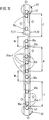
- Fig. 2 shows the device Fig. 1 simplified in front view
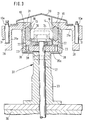
- Fig. 3 shows a carrier for Guide rails in cross section
- Fig. 4 a container carrier for Image of a plurality of containers in plan view
- FIGS. 5 and 6 Container carrier for containers with different from FIG. 4 Format in top view
- Fig. 7 to 9 container carrier for different Containers in cross section
- Fig. 11 a device in modified form according to Fig. 1 simplified in plan view.
- the device for intermittent feeding of containers 10a up to 10f to processing stations with filling and closing devices has two straight transport lanes 11 in a horizontal plane, 12 for the forward and return, each with a guide rail 13, 14.
- the guide rails 13, 14 on which the container carrier 15 can be moved have a flat hexagonal cross-sectional area.
- the Container carrier 15 consist of a plate-shaped carrier plate 19, on the side facing the guide rails 13, 14 two wedge-shaped guide strips 21, 22 attached are the wedge-shaped upper and lower edge areas 16, 17 of the guide rails 13, 14 enclose in a form-fitting manner.
- Below the lower guide bar 22 is a linear toothing in Form a rack 23 arranged on each support plate 19, the the transport of the container carrier 15 on the guide rails 13, 14 serves.
- each carrier plate 19 On the side facing away from the guide rails 13, 14 is on a mounting element 25a to 25f is attached to each carrier plate 19.
- the receiving elements 25a to 25f for example six, eight or twelve recesses 26a to 26c (Fig. 4 to 6), which are in regular Spaces formed in the receiving elements 25a to 25f are so that the length of the receiving elements 25a to 25f always the same and essentially corresponds to the length L of a carrier plate 19.
- the receiving elements 25d to 25f for example by terminals 27 or paragraphs 28, 29 (Fig. 7 to 9) to the terminal end, Upright or hanging transport of containers 10a to 10f used will.
- the transport tracks 11, 12 delimiting guide strips 31 arranged.
- the guide rails 13, 14 are fastened to supports 32 which are arranged on a table 30 are of the entire drive and control of the invention Includes device.
- the carriers 32 have a columnar shape Base 33, at its upper area via a U-shaped elbow 34 a cross arm 36 is attached, one on each side Guide rails 13, 14 carries. Is located below the cross arm 36 a transport gear 35a, which by means of a shaft 37 which through the base 33 is guided, is driven.
- the diameter of the Transport gear 35a is dimensioned so that it with its teeth 38 simultaneously into the racks 23 of two on the guide rails 13, 14 engages opposite container carrier 15, so that when the transport gear 35a rotates, the one container carrier 15 in one direction and the other container carrier 15 in the opposite direction on the respective guide rails 13, 14 is moved simultaneously.
- the upper area of the carrier 32 is covered with panels 39.
- the two ends of the guide rails 13, 14 each close a conversion device 40.
- the conversion devices 40 each take a container carrier 15 from one of the guide rails 13, 14, rotate this in the plane of the guide rails 13, 14 by 180 °, and give it to the other of the guide rails 13, 14. That I both conversion devices 40 in the same direction, for example Rotate counterclockwise, the container carriers will be in circulation mode 15 achieved on the guide rails 13, 14.
- Each of the conversion devices 40 is rotatably mounted in an axis 43 and has two connected to it via struts 44, opposite one another arranged rail pieces 45 for the container carrier 15.
- the rail pieces 45 the length of which is slightly greater than that Length L of the carrier plate 19 of the container carrier 15 have the same cross-sectional area as the guide rails 13, 14, and are at the same distance from each other, so that the two rail pieces 45 for receiving or delivering Container carriers 15 directly on the guide rails 13, 14 connect.
- container carriers 15 each with the same receiving elements 25a to 25f for different ones Container formats when changing the format of the guide rails 13, 14 removed, magazine and when changing to original container format returned.
- the container carriers 15 are stored in the format changeover device 50 in memory locations 51 magazines whose recordings 54, for example, like the rail pieces 45 of the conversion devices 40 are formed.
- the single ones Storage spaces 51, each with a container holder 15 space finds are vertical with a band or chain 52 in the form of a belt or chain conveyor designed to form a device with one another connected, which is attached to the table 30 by means of a column 55 is.
- the arrangement of the storage spaces 51 on the belt or chain conveyor is chosen so that each of the two extends Receiving rails 45 of a transfer device 40 each have a storage space 51 is located.
- a format gear 53 between two storage locations 51 arranged stationary.
- the format gear 53, the same diameter as the transfer gears 47 and the Has transport gears 35a causes the change in format Takeover of a container carrier 15 from a first rail piece 45 a conversion device 40 into the format changing device 50 simultaneous delivery of a container carrier 15 for another Container format from the format changing device 50 to the second Rail piece 45 of the transfer device 40.
- each of the two format changing devices 50 at least half of the storage spaces 51 is to be provided for container carriers 15 of a single format.
- it is a corresponding increase in the number of storage locations 51 also possible, for example one or more complete format sizes to magazine in one of the format changing devices 50 and to be handled by an appropriate control.
- only a format change device 50 corresponding Provide storage capacity at one end of the device.
- Both the transport gears 35a and the transfer gears 47 are synchronized, in the same direction of rotation, for example counterclockwise, and driven by the same angular amount in each case.
- the smallest sensible funding cycle causes the further transport of the Container carrier 15 around a container 10a to arranged on them 10f. This may be necessary, for example, if at a closing station only one container 10a to 10f at a time can be locked.
- the greatest possible funding cycle brings about that Further transport of the container carrier 15 by its length L.
- the largest possible Funding cycle is limited by the fact that each of the transfer devices 40 can only hold one container carrier 15 at a time.
- Zones K continuous funding created.
- the processing stations are moved with the container carriers 15, while in zones I intermittent production the processing stations are fixedly arranged on the device and the container carriers 15 are conveyed to them intermittently. This allows the processing times at zones K to be more continuous Funding regardless of the processing times of other processing stations be extended without breaks at zones I intermittent promotion comes, so the performance of the device is increased overall.
- the guide rails 13, 14 In contrast to intermittent funding, the example is based on Fig. 11, the guide rails 13, 14 not completely with container carriers 15 loaded. Furthermore, are between the guide rails 13, 14 arranged in the continuous zone K transport gears 35b, which are constantly driven at a constant angular velocity be, and in a transition zone M transport gears 35c, which depends on which of the guide rails 13, 14 these promote a container carrier 15, either an accelerating one or perform a decelerating rotation. Get it, for example Container carrier 15 from the intermittent zone I in the continuous zone K, these are in a zone M through the Transport gears 35c to the lower angular velocity of the Transport gears 35b in the continuous zone K decelerated and customized.
- the device according to the invention by creating more intermittent zones or continuous funding to the processing stations can be adjusted so that their flexibility and performance several successive processing steps of different Processing time is increased. Furthermore it is possible, multiple container carriers in zones K continuous funding 15 to be buffered, then by means of appropriately controlled Transport gears together in a group in a zone I intermittent funding. This allows the Processing time available for this association in the Intermittent Zone I increase, increasing device performance can also be increased.
Landscapes
- Engineering & Computer Science (AREA)
- Mechanical Engineering (AREA)
- Specific Conveyance Elements (AREA)
- Supplying Of Containers To The Packaging Station (AREA)
- Auxiliary Devices For And Details Of Packaging Control (AREA)
- Warehouses Or Storage Devices (AREA)
Claims (8)
- Dispositif de transport intermittent de récipients (10a à 10 f) vers au moins un poste de travail, en particulier un poste de remplissage et/ou un poste de fermeture, dispositif qui comprend plusieurs supports (15), recevant les récipients (10a à 10f) et deux rails de guidage parallèles (13, 14) pour l'aller et le retour des supports de récipients (15) ainsi que des dispositifs de transfert (40), disposés à leurs extrémités, pour les supports des récipients (15),
caractérisé en ce queles rails de guidage (13, 14) s'étendent dans un plan horizontal,sur les dispositifs de transfert (40) il est constitué des morceaux de rails (45) pour les supports de récipients (15), les morceaux de rails (45) se raccordant aux rails de guidage (13, 14) et pouvant tourner autour d'un axe (43) disposé perpendiculairement au sens d'avancement des supports de récipients (15) etles supports de récipients (15) présentent une denture linéaire (23) qui s'étend dans le sens de leur avancement et qui vient en prise avec des roues dentées de transport (35a à 35c), motrices, disposées dans les rails de guidage (13, 14). - Dispositif selon la revendication 1,
caractérisé en ce quele long des rails de guidage (13, 14) on dispose plusieurs roues de transport (35a à 35c), entraínées indépendamment les unes des autres, qui servent à transporter les supports de récipients (15) etles rails de guidage (13, 14) ont au moins une zone (K) dans laquelle on fait avancer les supports de récipients (15) de façon continue. - Dispositif selon la revendication 1 ou 2,
caractérisé en ce que
le diamètre des roues dentées de transport (35a à 35c) est adapté à la distance comprise entre les rails de guidage (13, 14), de telle sorte que les roues dentées de transport (35a à 35c), qui sont disposées entre ceux-ci, font avancer en même temps les supports de récipients (15) sur les deux rails de guidage (13, 14). - Dispositif selon l'une des revendications 1 à 3,
caractérisé en ce que
sur au moins un dispositif de transfert (40) on dispose un dispositif de changement de format (50) pour les supports de récipients (15). - Dispositif selon la revendication 4,
caractérisé en ce que
le dispositif de changement de format (50) est disposé à proximité du dispositif de transfert (40) sur le côté qui est situé à l'opposé des rails de guidage (13, 14) - Dispositif selon l'une des revendications 1 à 5,
caractérisé en ce que
les supports de récipients (15) ont des évidements (26a à 26c), et des logements (27 à 29) qui sont adaptés au format et au nombre des récipients (10a à 10f). - Dispositif selon l'une des revendications 1 à 6,
caractérisé en ce que
la longueur des rails de guidage (13, 14) est un multiple de la largeur (L) d'un support de récipients (15). - Dispositif selon l'une des revendications 1 à 7,
caractérisé en ce que
les rails de guidage (13, 14) ont des côtés opposés (16, 17) constitués en forme de coin qui viennent en prise dans des barres de guidage correspondantes (21, 22) des supports de récipients (15), correspondantes, constituées en forme de coin.
Applications Claiming Priority (3)
| Application Number | Priority Date | Filing Date | Title |
|---|---|---|---|
| DE4320477A DE4320477A1 (de) | 1993-06-21 | 1993-06-21 | Vorrichtung zum intermittierenden Transport von Behältnissen |
| DE4320477 | 1993-06-21 | ||
| PCT/DE1994/000649 WO1995000397A1 (fr) | 1993-06-21 | 1994-06-10 | Dispositif de transport intermittent de recipients |
Publications (2)
| Publication Number | Publication Date |
|---|---|
| EP0679136A1 EP0679136A1 (fr) | 1995-11-02 |
| EP0679136B1 true EP0679136B1 (fr) | 1998-06-10 |
Family
ID=6490797
Family Applications (1)
| Application Number | Title | Priority Date | Filing Date |
|---|---|---|---|
| EP94916897A Expired - Lifetime EP0679136B1 (fr) | 1993-06-21 | 1994-06-10 | Dispositif de transport intermittent de recipients |
Country Status (6)
| Country | Link |
|---|---|
| US (1) | US5582220A (fr) |
| EP (1) | EP0679136B1 (fr) |
| JP (1) | JP3660949B2 (fr) |
| DE (2) | DE4320477A1 (fr) |
| DK (1) | DK0679136T3 (fr) |
| WO (1) | WO1995000397A1 (fr) |
Families Citing this family (9)
| Publication number | Priority date | Publication date | Assignee | Title |
|---|---|---|---|---|
| DE19724105C1 (de) * | 1997-06-07 | 1998-10-08 | Bosch Gmbh Robert | Befestigungseinrichtung für einen Behältnisträger an einer Transportvorrichtung |
| JP4672936B2 (ja) * | 2001-09-28 | 2011-04-20 | 靜甲株式会社 | 容器追従式包装機システム |
| DE10360082A1 (de) * | 2003-12-20 | 2005-07-21 | Robert Bosch Gmbh | Vorrichtung zur Behandlung von Behältnissen |
| DE102007024446A1 (de) | 2007-05-25 | 2008-11-27 | Groninger & Co. Gmbh | Vorrichtung zum Transport von Behältnissen zu mindestens einer Bearbeitungsstation |
| EP2006204B1 (fr) * | 2007-06-18 | 2009-05-13 | UHLMANN PAC-SYSTEME GmbH & Co. KG | Installation destinée à la mise en bouteille de produits pharmaceutiques dans des récipients de types bouteilles |
| JP5117130B2 (ja) * | 2007-07-10 | 2013-01-09 | 株式会社ケーテー製作所 | シリンジ搬送装置 |
| DE102012020307B3 (de) * | 2012-10-16 | 2014-03-13 | Hamba Filltec Gmbh & Co. Kg | Vorrichtung zum Befüllen von Behältern mit Nahrungsmitteln |
| DE102020103579A1 (de) | 2020-02-12 | 2021-08-12 | Mfp Gesellschaft Für Engineering Mbh | Transportvorrichtung zum taktenden Transport von Verpackungen zur Verwendung in Abfüllanlagen |
| CN113080951B (zh) * | 2021-04-09 | 2022-08-09 | 佳木斯大学 | 一种采血托架装置及操作方法 |
Family Cites Families (9)
| Publication number | Priority date | Publication date | Assignee | Title |
|---|---|---|---|---|
| CA553161A (fr) * | 1958-02-11 | H. Berch Samuel | Machine a empaqueter pour creme glacee | |
| US798244A (en) * | 1903-12-07 | 1905-08-29 | John T Wilmore | Canning apparatus. |
| US2701674A (en) * | 1951-11-15 | 1955-02-08 | Andrew L Christiansen | Fish canning machine |
| US3610391A (en) * | 1970-03-20 | 1971-10-05 | Btu Eng Corp | Furnace conveyor system |
| US3800937A (en) * | 1971-08-09 | 1974-04-02 | Gen Electric | Conveyor mechanism |
| IT976523B (it) * | 1973-01-29 | 1974-09-10 | Cioni E | Attrezzatura di avanzamento per macchine di manipolazione delle fia le od altro |
| FR2537108B1 (fr) * | 1982-12-01 | 1987-04-03 | Dubuit Mach | Dispositif de transfert pour la circulation de supports porte-objet au droit d'au moins un poste de traitement |
| DE3918072C2 (de) * | 1989-06-02 | 1995-06-01 | Icoma Packtechnik Gmbh | Transportvorrichtung für die Kassetten einer Füllanlage |
| DE4314613C2 (de) * | 1993-05-04 | 2003-02-20 | Bosch Gmbh Robert | Verpackungsmaschine |
-
1993
- 1993-06-21 DE DE4320477A patent/DE4320477A1/de not_active Withdrawn
-
1994
- 1994-06-10 JP JP50230995A patent/JP3660949B2/ja not_active Expired - Lifetime
- 1994-06-10 DE DE59406216T patent/DE59406216D1/de not_active Expired - Lifetime
- 1994-06-10 DK DK94916897T patent/DK0679136T3/da active
- 1994-06-10 EP EP94916897A patent/EP0679136B1/fr not_active Expired - Lifetime
- 1994-06-10 US US08/373,319 patent/US5582220A/en not_active Expired - Fee Related
- 1994-06-10 WO PCT/DE1994/000649 patent/WO1995000397A1/fr not_active Ceased
Also Published As
| Publication number | Publication date |
|---|---|
| DE4320477A1 (de) | 1994-12-22 |
| DK0679136T3 (da) | 1999-03-22 |
| JP3660949B2 (ja) | 2005-06-15 |
| JPH08500567A (ja) | 1996-01-23 |
| EP0679136A1 (fr) | 1995-11-02 |
| WO1995000397A1 (fr) | 1995-01-05 |
| DE59406216D1 (de) | 1998-07-16 |
| US5582220A (en) | 1996-12-10 |
Similar Documents
| Publication | Publication Date | Title |
|---|---|---|
| DE102007059611B4 (de) | Verfahren und Vorrichtung zum Transportieren von Objekten | |
| EP0062267B1 (fr) | Système de fabrication et d'assemblage | |
| DE3215160C2 (fr) | ||
| DD140559A5 (de) | Fertigungsanlage fuer in zwei oder mehreren schritten herzustellende bauteile | |
| DE2543621C2 (de) | Kannenwechseleinrichtung | |
| DE3141784C2 (de) | Vorrichtung zum Zu- und Wegführen von Statoren elektrischer Maschinen | |
| EP0679136B1 (fr) | Dispositif de transport intermittent de recipients | |
| DE102018002280A1 (de) | Endlos umlaufende Behälter-Fördervorrichtung in einer Verpackungsmaschine | |
| DE3416499A1 (de) | Vorrichtung zum zufuehren von gegenstaenden zu einer verpackungsstation | |
| DE69401969T2 (de) | Kommissionier-Verfahren und -Vorrichtung | |
| DE69404230T2 (de) | Überführungseinrichtung für Glasgegenstände | |
| EP3870512B1 (fr) | Procédé et dispositif pour remplir un contenant avec des produits | |
| DE3808157A1 (de) | Muenzen-stapelvorrichtung | |
| DE2106091C3 (de) | Vorrichtung zum verschachtelten, lageweisen Stapeln von profiliertem Walzgut | |
| DE2433804A1 (de) | System zur handhabung von gegenstaenden | |
| DE10110787A1 (de) | Verfahren und Vorrichtung zum Verpacken von länglichen Gegenständen | |
| EP0378778A1 (fr) | Dispositif de stockage à chaîne | |
| DE19626361A1 (de) | Maschine zum Transportieren von Flaschen oder ähnlichen Behältern | |
| DE20110837U1 (de) | Montagelinie | |
| EP1516834B1 (fr) | Dispositif pour transporter les récipients emboîtés | |
| DE2301733A1 (de) | Transportsystem fuer werkstuecktraeger | |
| DE8627162U1 (de) | Vorrichtung zum wechselweise kontinuierlichen bzw. getakteten Weitertransport von Tragteilen | |
| EP0885100B1 (fr) | Dispositif de chargement pour presse a plateau | |
| DE69117732T2 (de) | Beschickungsförderer mit Verwendung mehrfacher Mitnehmer | |
| DE4404744C1 (de) | Einlegestation |
Legal Events
| Date | Code | Title | Description |
|---|---|---|---|
| PUAI | Public reference made under article 153(3) epc to a published international application that has entered the european phase |
Free format text: ORIGINAL CODE: 0009012 |
|
| 17P | Request for examination filed |
Effective date: 19950705 |
|
| AK | Designated contracting states |
Kind code of ref document: A1 Designated state(s): CH DE DK FR IT LI |
|
| 17Q | First examination report despatched |
Effective date: 19961212 |
|
| GRAG | Despatch of communication of intention to grant |
Free format text: ORIGINAL CODE: EPIDOS AGRA |
|
| GRAG | Despatch of communication of intention to grant |
Free format text: ORIGINAL CODE: EPIDOS AGRA |
|
| GRAH | Despatch of communication of intention to grant a patent |
Free format text: ORIGINAL CODE: EPIDOS IGRA |
|
| GRAH | Despatch of communication of intention to grant a patent |
Free format text: ORIGINAL CODE: EPIDOS IGRA |
|
| GRAA | (expected) grant |
Free format text: ORIGINAL CODE: 0009210 |
|
| AK | Designated contracting states |
Kind code of ref document: B1 Designated state(s): CH DE DK FR IT LI |
|
| REG | Reference to a national code |
Ref country code: CH Ref legal event code: NV Representative=s name: SCINTILLA AG, DIREKTION Ref country code: CH Ref legal event code: EP |
|
| REF | Corresponds to: |
Ref document number: 59406216 Country of ref document: DE Date of ref document: 19980716 |
|
| ITF | It: translation for a ep patent filed | ||
| ET | Fr: translation filed | ||
| REG | Reference to a national code |
Ref country code: DK Ref legal event code: T3 |
|
| PLBE | No opposition filed within time limit |
Free format text: ORIGINAL CODE: 0009261 |
|
| STAA | Information on the status of an ep patent application or granted ep patent |
Free format text: STATUS: NO OPPOSITION FILED WITHIN TIME LIMIT |
|
| 26N | No opposition filed | ||
| PGFP | Annual fee paid to national office [announced via postgrant information from national office to epo] |
Ref country code: FR Payment date: 20030619 Year of fee payment: 10 |
|
| PGFP | Annual fee paid to national office [announced via postgrant information from national office to epo] |
Ref country code: CH Payment date: 20030624 Year of fee payment: 10 |
|
| PGFP | Annual fee paid to national office [announced via postgrant information from national office to epo] |
Ref country code: DK Payment date: 20040622 Year of fee payment: 11 |
|
| PG25 | Lapsed in a contracting state [announced via postgrant information from national office to epo] |
Ref country code: LI Free format text: LAPSE BECAUSE OF NON-PAYMENT OF DUE FEES Effective date: 20040630 Ref country code: CH Free format text: LAPSE BECAUSE OF NON-PAYMENT OF DUE FEES Effective date: 20040630 |
|
| REG | Reference to a national code |
Ref country code: CH Ref legal event code: PL |
|
| PG25 | Lapsed in a contracting state [announced via postgrant information from national office to epo] |
Ref country code: FR Free format text: LAPSE BECAUSE OF NON-PAYMENT OF DUE FEES Effective date: 20050228 |
|
| REG | Reference to a national code |
Ref country code: FR Ref legal event code: ST |
|
| PG25 | Lapsed in a contracting state [announced via postgrant information from national office to epo] |
Ref country code: DK Free format text: LAPSE BECAUSE OF NON-PAYMENT OF DUE FEES Effective date: 20050630 |
|
| REG | Reference to a national code |
Ref country code: DK Ref legal event code: EBP |
|
| PGFP | Annual fee paid to national office [announced via postgrant information from national office to epo] |
Ref country code: DE Payment date: 20130828 Year of fee payment: 20 |
|
| PGFP | Annual fee paid to national office [announced via postgrant information from national office to epo] |
Ref country code: IT Payment date: 20130622 Year of fee payment: 20 |
|
| REG | Reference to a national code |
Ref country code: DE Ref legal event code: R071 Ref document number: 59406216 Country of ref document: DE |
|
| PG25 | Lapsed in a contracting state [announced via postgrant information from national office to epo] |
Ref country code: DE Free format text: LAPSE BECAUSE OF EXPIRATION OF PROTECTION Effective date: 20140611 |