EP0678481A2 - Formfinger zur Formung eines Mündungsbereiches an einem Glasfläschchen - Google Patents
Formfinger zur Formung eines Mündungsbereiches an einem Glasfläschchen Download PDFInfo
- Publication number
- EP0678481A2 EP0678481A2 EP95109973A EP95109973A EP0678481A2 EP 0678481 A2 EP0678481 A2 EP 0678481A2 EP 95109973 A EP95109973 A EP 95109973A EP 95109973 A EP95109973 A EP 95109973A EP 0678481 A2 EP0678481 A2 EP 0678481A2
- Authority
- EP
- European Patent Office
- Prior art keywords
- finger
- circular section
- area
- mouth
- shaping
- Prior art date
- Legal status (The legal status is an assumption and is not a legal conclusion. Google has not performed a legal analysis and makes no representation as to the accuracy of the status listed.)
- Ceased
Links
Images
Classifications
-
- C—CHEMISTRY; METALLURGY
- C03—GLASS; MINERAL OR SLAG WOOL
- C03B—MANUFACTURE, SHAPING, OR SUPPLEMENTARY PROCESSES
- C03B23/00—Re-forming shaped glass
- C03B23/04—Re-forming tubes or rods
- C03B23/11—Reshaping by drawing without blowing, in combination with separating, e.g. for making ampoules
- C03B23/112—Apparatus for conveying the tubes or rods in a curved path around a vertical axis through one or more forming stations
-
- C—CHEMISTRY; METALLURGY
- C03—GLASS; MINERAL OR SLAG WOOL
- C03B—MANUFACTURE, SHAPING, OR SUPPLEMENTARY PROCESSES
- C03B23/00—Re-forming shaped glass
- C03B23/04—Re-forming tubes or rods
- C03B23/09—Reshaping the ends, e.g. as grooves, threads or mouths
- C03B23/095—Reshaping the ends, e.g. as grooves, threads or mouths by rolling
Definitions
- the invention relates to a shaped finger for supporting the shape of the mouth region of a vial, the mouth region of which is formed at the open, heat-softened end of a glass tube. Vials, such as ampoules, snap-cap jars, rolled rim vials, etc. are then produced from the shaped glass tube end.
- These small vials or ampoules are made from glass tubes in vial machines, in which a large number of glass tubes are kept rotated about their own longitudinal axis and gradually fed to individual forming stations. At such a molding station, the mouth area is also formed by rolling in the glass tube end using one or more molding rollers.
- Form fingers for forming the mouth area of a glass tube are already known from DE-C-15 96 410, 17 96 100, 36 13 212 and CA-C-581053. These form fingers all have the shape of a cylinder with a circular cross section. In some cases the cylinder is rounded or beveled at the edge. These cylinders, the outer circumference of which corresponds to the inner circumference of the workpiece to be shaped, are inserted into the open end of the glass tube and serve as an inner support for the form rollers, which process the heat-softened area of the glass tube to be deformed from the outside.
- the shaping finger Since the molding finger is in contact with the heat-softened glass for a long time during the shaping of the glass tube, the shaping finger must be made from a high-quality, heat-resistant material It is necessary to change the shape finger, in which case bottle production must be stopped each time.
- the object of the present invention is therefore to provide a shaped finger, the special design of which keeps wear as low as possible.
- a special design of the shaping finger or the holding of the shaping finger can thus reduce wear and the inaccuracies that occur when shaping the mouth.
- a shaped finger according to the invention which is guided for the inner shaping of a mouth region into an open, heat-soft end of a glass tube that is rolled up by a shaping roller, is characterized in that it has a cross-sectional area that deviates from the usual circular cross-section and that only has one or has a plurality of circular section areas which come into contact with the inner circumference of the mouth area and determine the inner radius of the mouth, but the cross-sectional area of the shaping finger as a whole is kept so large that the ratio of the cross-sectional area to the arc length of the (or) circular section area (s) ⁇ 0 , 55 r. where r is the radius of the circular section area.
- the form finger which is only with its (n) circular section area (s) comes into contact with the heat-softened glass tube end, has a relatively larger cross-sectional area for dissipating the amount of heat transferred to the form finger during this contact than a circle with the same radius or a corresponding pie-shaped circle segment.
- This measure allows the shaped finger according to the invention to dissipate the amount of heat transferred from its heat-softened glass tube end over its circular section area to its holder more quickly than a corresponding cylindrical shaped finger, as a result of which the shaped finger according to the invention produces less heating under otherwise identical operating conditions.
- the cross-sectional area of the shaped finger is not reduced to less than half the area of the full circle placed over the circular section area (s), ie if the cross-sectional area ⁇ 0.5r2. ⁇ is so that there is still sufficient mass for heat dissipation.
- the circular section area should also not be too small, so that a sufficient smoothing of the inner circumference of the mouth area is ensured.
- a circular section range from 60 ° to 190 ° is advantageous, the circular section preferably being selected in a range from 100 ° to 150 °. If the shaped finger has, for example, two opposing circular section regions, these are preferably each in the range from 100 ° to 150 °.
- the shaped finger In order to support the lower glass edge of the heat-softened glass tube end, the shaped finger preferably has a support at its lower end which has a circular peripheral surface and is arranged concentrically to the shaped finger, the radius of this support being larger than the radius of the circular section area.
- a step-shaped profiled form roller is then attached to such a form finger in such a way that the smaller form roller radius attaches to the circumferential surface of this support and, with the profile part with a larger radius, delimits an essentially rectangular cavity in cross-section area in which the heat-softened glass tube end becomes one Rolled edge or flanged edge of the Vial mouth is molded.
- the radius of the circular section again determines the inner radius of the mouth, the larger radius of the form roller the outer radius of the bottle neck and the smaller radius of the form roller the outer radius of the rolled rim.
- the radius of the circular section depends on the desired inner radius of the mouth.
- Form fingers with a radius between 2 mm and 20 mm can be used for special applications.
- the support on which the end of the glass tube is seated can have a surface sloping towards the center. This creates a conical mirror surface on the top of the bottle.
- the sloping surface can be at an angle of e.g. 5 ° or 7 °.
- the circumferential surface of the support can also have a recess in the area where the shaping roller is attached, so that the radius of the support is somewhat reduced in this area. This enables the outside diameter of the edge of the vial to be reduced, since the shaped disk can penetrate closer to the shaped finger here.
- undercuts can also be produced in the mouth area of the vial to be shaped.
- the upper part of the circular section area then has an extended projecting edge which can be designed as a step or as a slope and correspondingly represents a second circular section area with a larger radius than the first circular section area, both circular section areas are arranged concentrically.
- the rear area is then also milled free with respect to a solid cylinder, so that the shape finger can first be pushed back somewhat in the radial direction from the contact point of the circular section area / inner circumference of the mouth after the shaping has been completed, in order then to be pulled out without touching the mouth.
- Such a form finger is preferably used in conjunction with only one form roller, since the previously generally used use of two form rollers would have to use two correspondingly shaped form finger halves which can be displaced relative to one another and which, in order that they can be pushed together, have only a very small cross-sectional area with respect to a corresponding full circle can have, whereby a sufficient dissipation of heat is no longer guaranteed in every case.
- the above-described embodiments of the shaping finger according to the invention can be used with particular advantage when using only one shaping roller. If two form rollers are to be rolled in at 180 ° on the glass tube, the form finger according to the invention is to be designed in a D 2h symmetry (symmetry of the cross section), two opposing circular section regions then being assigned to the form rollers.
- D 2h symmetry symmetry of the cross section
- the use of only one form roller and one shape finger with C 2v symmetry is particularly advantageous, since then no expensive means for pivoting against one another or moving two shape fingers in the mouth are necessary.
- the form finger can be sprayed with oil during operation, which can run practically over the entire form finger and is expediently collected in an oil collecting pan located directly below the form finger and is derived therefrom.
- oil collecting pan located directly below the form finger and is derived therefrom.
- Such an oil drip pan and, if necessary, corresponding bores can in principle be used successfully with all shaped fingers.
- the molding finger can advantageously also be designed with a little horizontal play or can be inserted into the heat-softened glass tube end with such play, as described in the European patent application EP 91 113 745.3.
- the horizontal play allows a largely free movement of the form finger radially to the longitudinal axis of the glass tube. This can be achieved, for example, by placing the form finger on an articulated bearing.
- the shape finger expediently has the shape of a cylinder flattened on both sides with two remaining circular section areas of preferably 100 ° to 150 °. Circular section areas of approximately 135 ° have proven to be particularly favorable.
- the mold fingers described above and here, which differ from the solid cylinder, have the advantage, in addition to the better heat dissipation properties, that the molding oil which is dripped onto the mold finger at the top can run off better on the free millings during the formation of the mouth.
- the glass to be molded can therefore better fit the circular section areas.
- the shaped finger according to the invention is used particularly advantageously in the device described in European patent application EP 91 113 745.3.
- it can also be made of an inexpensive, less high-temperature resistant material such as. B. Silver steel (material number according to the German steel key 1.2210) instead of the previously common Tyrodur steel (material number 1.2842).
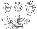
- FIG. 1a A shaped finger according to the invention is shown in FIG. 1a.
- This form finger 11 is a part of an originally cylindrical form 30, on which approx. 40% of the rear area 31 and each approx. 7% of the lateral areas 32 (the percentages relate to the original diameter of the cylindrical shape 30).
- This shaping finger 11 has a circular section area 33, which still has the original function of the shaping finger, namely the smoothing and support (shaping) of the interior of the mouth to be shaped.
- the circular section area 33 covers an angle of approximately 130 ° at which the shaping roller 29 can start and form. Corresponding to the angle of 130 °, the circular section area 33 has an arc length of 2.r. ⁇ . 130 ° / 360 °, where r is the radius of the circular section area. Forming can no longer take place on the other sides of the forming finger 11, this forming finger 11 is therefore only intended for use in vial machines with one forming roller per forming station (as shown, for example, in FIG. 1).
- the area of approx. 130 ° of a full cylinder covered by the circular section area 33 depends on the structural conditions of a vial machine or molding station used in each case.
- the molding finger If it is to be possible to shape the molding finger by 180 ° or more, only the rear area 31 is to be removed from a solid cylinder. Normally, however, a circular section area 33 of less than 180 ° is sufficient and also desirable, since the removal of the rear area 31 and the lateral areas 32 reduces the cross section of the shaped finger so that it is light and even without touching the inner circumference of a finished mouth can be pulled out of this.
- Figure 1b shows a shaped finger 11, the cross section of which has a D 2h symmetry. Compared to the cylindrical shape 30, only the lateral areas 32 are milled free.
- This form finger 11 has two circular section areas 33 at an angle of approx. 135 ° each and is used in a molding with two molding rollers or in a movable mounting of the molding finger (described below).
- a support 34 can be provided for a mouth edge to be shaped.
- This support 34 has essentially the shape of a cylindrical disk 35 with a larger diameter than the cylindrical shape 30 and is arranged concentrically to this.
- the cylindrical disk 35 has a recess 36 below the circular section area 33, which forms a free space for the form roller 29, so that it can penetrate closer to the form finger 11 than is the nominal dimension of the rolled edge outer diameter of a vial to be shaped.
- FIG. 3 Such a situation is shown in FIG. 3.
- the cylindrical disc 35 is attached to a piston 10 at 37 (e.g., by means of a screw).
- An oil drip pan 38 is arranged between the piston 10 and the cylindrical disk 35, which collects molding oil sprayed over the molding finger 11 and returns it via an outlet 39.
- the support 34 has a surface 40 that slopes towards the center of the shaping finger and that forms the upper edge of a vial mouth 41.
- the bevel has an angle of 5 ° and depends on the intended use of the vial to be manufactured.
- the molding oil can run off over the entire molding finger 11 and the cylindrical disk 35, or can also be discharged through channels 42 through the cylindrical disk.
- the turned glass tube 5 is pressed against the circular section region 33 of the end 25 by means of the shaping roller 29
- Form fingers 11 pressed.
- the form roller 29 has on its edge a profile 43, the outwardly projecting part 44 presses the glass tube end 25 against the circular section area 33 and thereby forms a bottle neck 45.
- a somewhat thicker glass bead is formed in front of an inwardly projecting part 46 of the profile 43 and is formed into a flanged or rolled edge 47 in contact with the circular section region 33 and the inclined surface 40.
- the shaping roller 29 can penetrate somewhat closer to the shaping finger 11 in the region of the recess 36, so that a small glass item 48 is pressed into the free space formed by the recess 36.
- an enlarged rim 49 or collar can be provided at the upper end of the shaping finger 11, which collar forms an undercut in the vial neck 45.
- this shaping finger 11 must either be displaced radially or pulled out obliquely from the finished vial mouth 41.
- Such a pulling out of the shaped finger is also useful if no extended edge 49 is provided, since in this case the circular section area 33 is removed from the mouth without touching the inner wall thereof.
- the rear area and the lateral areas e.g. be removed in the manner of an oval.
- the largest possible cross-sectional area of the forming finger should remain so that the heat absorbed at the circular section area can be dissipated quickly.
Landscapes
- Chemical & Material Sciences (AREA)
- Engineering & Computer Science (AREA)
- Materials Engineering (AREA)
- Organic Chemistry (AREA)
- Re-Forming, After-Treatment, Cutting And Transporting Of Glass Products (AREA)
- Containers Having Bodies Formed In One Piece (AREA)
Applications Claiming Priority (3)
| Application Number | Priority Date | Filing Date | Title |
|---|---|---|---|
| DE4028823 | 1990-09-11 | ||
| DE4028823A DE4028823C2 (de) | 1990-09-11 | 1990-09-11 | Vorrichtung und Formfinger zum Formen eines Mündungsbereiches an einem Glasfläschchen |
| EP91113745A EP0475112B1 (de) | 1990-09-11 | 1991-08-16 | Vorrichtung zur Formung eines Mündungsbereiches an einem Glasfläschchen |
Related Parent Applications (2)
| Application Number | Title | Priority Date | Filing Date |
|---|---|---|---|
| EP91113745A Division-Into EP0475112B1 (de) | 1990-09-11 | 1991-08-16 | Vorrichtung zur Formung eines Mündungsbereiches an einem Glasfläschchen |
| EP91113745.3 Division | 1991-08-16 |
Publications (2)
| Publication Number | Publication Date |
|---|---|
| EP0678481A2 true EP0678481A2 (de) | 1995-10-25 |
| EP0678481A3 EP0678481A3 (ref) | 1995-11-22 |
Family
ID=6414041
Family Applications (2)
| Application Number | Title | Priority Date | Filing Date |
|---|---|---|---|
| EP95109973A Ceased EP0678481A2 (de) | 1990-09-11 | 1991-08-16 | Formfinger zur Formung eines Mündungsbereiches an einem Glasfläschchen |
| EP91113745A Expired - Lifetime EP0475112B1 (de) | 1990-09-11 | 1991-08-16 | Vorrichtung zur Formung eines Mündungsbereiches an einem Glasfläschchen |
Family Applications After (1)
| Application Number | Title | Priority Date | Filing Date |
|---|---|---|---|
| EP91113745A Expired - Lifetime EP0475112B1 (de) | 1990-09-11 | 1991-08-16 | Vorrichtung zur Formung eines Mündungsbereiches an einem Glasfläschchen |
Country Status (6)
| Country | Link |
|---|---|
| US (1) | US5252115A (ref) |
| EP (2) | EP0678481A2 (ref) |
| JP (1) | JPH04231333A (ref) |
| CA (1) | CA2051184A1 (ref) |
| DE (2) | DE4028823C2 (ref) |
| ES (1) | ES2083492T3 (ref) |
Families Citing this family (11)
| Publication number | Priority date | Publication date | Assignee | Title |
|---|---|---|---|---|
| DE102004014170B3 (de) * | 2004-03-17 | 2005-10-27 | Ambeg - Dr. J. Dichter Gmbh | Glasbearbeitungsmaschine und Steuerungsverfahren hierfür |
| ES2392645T3 (es) * | 2004-09-30 | 2012-12-12 | Becton,Dickinson And Company | Método para reducir o eliminar residuos en una recipiente médico de vidrio y recipiente hecho de acuerdo con el mismo |
| DE102016123865A1 (de) | 2016-12-08 | 2018-06-14 | Schott Ag | Verfahren zum Weiterverarbeiten eines Glasrohr-Halbzeugs einschließlich einer thermischen Umformung |
| DE102016124833A1 (de) * | 2016-12-19 | 2018-06-21 | Schott Ag | Verfahren zum Herstellen eines Hohlglasprodukts aus einem Glasrohr-Halbzeug mit Markierungen, sowie Verwendungen hiervon |
| DE102016125129A1 (de) | 2016-12-21 | 2018-06-21 | Schott Ag | Verfahren zum Herstellen eines Glasrohr-Halbzeugs oder eines daraus hergestellten Hohlglasprodukts mit Markierungen, sowie Verwendungen hiervon |
| US10968133B2 (en) | 2017-11-30 | 2021-04-06 | Corning Incorporated | Methods for minimizing SHR in glass articles by producing a gas flow during pharmaceutical part converting |
| US11186513B2 (en) | 2017-11-30 | 2021-11-30 | Corning Incorporated | Systems and methods for minimizing SHR from pharmaceutical part converting using negative pressure evacuation |
| US11339079B2 (en) | 2017-11-30 | 2022-05-24 | Corning Incorporated | Systems and methods for minimizing SHR from pharmaceutical part converting using pulsed ejection |
| US11420893B2 (en) | 2017-11-30 | 2022-08-23 | Corning Incorporated | Systems and methods for minimizing SHR from piercing during pharmaceutical part converting using a gas flow |
| DE102018126053A1 (de) * | 2018-10-19 | 2020-04-23 | Schott Schweiz Ag | Verfahren und Vorrichtung zur Heißumformung von gläsernen Werkstücken und heißumgeformte Glasbehälter |
| EP4530266A1 (en) * | 2023-09-28 | 2025-04-02 | SCHOTT Pharma AG & Co. KGaA | Hot forming tool for glass bottle necks |
Citations (4)
| Publication number | Priority date | Publication date | Assignee | Title |
|---|---|---|---|---|
| CA581053A (en) | 1959-08-11 | C. Kahle Louis | Method and apparatus for producing glass articles | |
| DE1596410A1 (de) | 1966-11-29 | 1971-04-01 | Dichter Jakob Dr Ing C H | Maschine zum Herstellen von Artikeln aus thermoplastischem Material,insbesondere Glas |
| DE1796100A1 (de) | 1968-08-30 | 1972-02-24 | Dichter Hans Joachim | Vorrichtung zum Formen von Flaschenhaelsen |
| DE3613212C1 (de) | 1986-04-17 | 1987-07-02 | Dichter Hans Joachim | Vorrichtung zum Formen des Halses von aus Glasrohren hergestellten Glasflaschen |
Family Cites Families (8)
| Publication number | Priority date | Publication date | Assignee | Title |
|---|---|---|---|---|
| US416559A (en) * | 1889-12-03 | beady | ||
| US1006383A (en) * | 1910-12-29 | 1911-10-17 | Robert Johns | Neck-grooving attachment for bottle-molding machines. |
| US1229028A (en) * | 1913-09-06 | 1917-06-05 | Louis Naglee Bruner | Apparatus for use in the manufacture of glass bottles and the like. |
| US3449105A (en) * | 1966-03-11 | 1969-06-10 | Corning Glass Works | Flexible shaping tool |
| US4284447A (en) * | 1976-02-20 | 1981-08-18 | Dickens Luther I | Method of manufacturing a composite panel |
| IT1120161B (it) * | 1979-11-27 | 1986-03-19 | Ermanno Vertova | Metodo e macchina per la formazione di fiale ottenute da tubo di vetro |
| US4441908A (en) * | 1981-03-30 | 1984-04-10 | Owens-Illinois, Inc. | Vial tooling apparatus |
| CH663408A5 (en) * | 1984-03-02 | 1987-12-15 | Owens Illinois Inc | Machine for working regions of preforms made of thermoplastic material |
-
1990
- 1990-09-11 DE DE4028823A patent/DE4028823C2/de not_active Expired - Fee Related
-
1991
- 1991-08-16 ES ES91113745T patent/ES2083492T3/es not_active Expired - Lifetime
- 1991-08-16 EP EP95109973A patent/EP0678481A2/de not_active Ceased
- 1991-08-16 DE DE59107422T patent/DE59107422D1/de not_active Expired - Fee Related
- 1991-08-16 EP EP91113745A patent/EP0475112B1/de not_active Expired - Lifetime
- 1991-09-10 US US07/756,845 patent/US5252115A/en not_active Expired - Fee Related
- 1991-09-11 JP JP3258688A patent/JPH04231333A/ja active Pending
- 1991-09-11 CA CA002051184A patent/CA2051184A1/en not_active Abandoned
Patent Citations (4)
| Publication number | Priority date | Publication date | Assignee | Title |
|---|---|---|---|---|
| CA581053A (en) | 1959-08-11 | C. Kahle Louis | Method and apparatus for producing glass articles | |
| DE1596410A1 (de) | 1966-11-29 | 1971-04-01 | Dichter Jakob Dr Ing C H | Maschine zum Herstellen von Artikeln aus thermoplastischem Material,insbesondere Glas |
| DE1796100A1 (de) | 1968-08-30 | 1972-02-24 | Dichter Hans Joachim | Vorrichtung zum Formen von Flaschenhaelsen |
| DE3613212C1 (de) | 1986-04-17 | 1987-07-02 | Dichter Hans Joachim | Vorrichtung zum Formen des Halses von aus Glasrohren hergestellten Glasflaschen |
Also Published As
| Publication number | Publication date |
|---|---|
| JPH04231333A (ja) | 1992-08-20 |
| US5252115A (en) | 1993-10-12 |
| EP0475112B1 (de) | 1996-02-21 |
| DE4028823A1 (de) | 1992-03-12 |
| EP0475112A3 (en) | 1993-01-20 |
| CA2051184A1 (en) | 1992-03-12 |
| EP0475112A2 (de) | 1992-03-18 |
| DE59107422D1 (de) | 1996-03-28 |
| ES2083492T3 (es) | 1996-04-16 |
| DE4028823C2 (de) | 1994-07-07 |
| EP0678481A3 (ref) | 1995-11-22 |
Similar Documents
| Publication | Publication Date | Title |
|---|---|---|
| EP0473769A1 (de) | Vorrichtung zur herstellung von tuben. | |
| EP0630734B1 (de) | Verfahren zur Entformung von Spritzgusshohlkörpern mit Hinterschneidungen in der Innenkontur und zugehöriger Formkern | |
| EP0553609B1 (de) | Verfahren zum Spritzgiessen von Gegenständen aus wenigstens zwei Teilen | |
| EP0475047B1 (de) | Vorrichtung und Verfahren zum Verformen des wärmeerweichten Endes eines Glasrohres und Verwendung der Vorrichtung in einer Fläschchenmaschine | |
| DE2142570A1 (de) | Vorrichtung zum Formen von zu sinternden Teilen | |
| DE1527947A1 (de) | Verfahren und Vorrichtung zum Herstellen und Bearbeiten von becherfoermigen Werkstuecken | |
| DE3623099C2 (de) | Blasformmaschine | |
| EP0475112B1 (de) | Vorrichtung zur Formung eines Mündungsbereiches an einem Glasfläschchen | |
| DE69927732T2 (de) | Zahnrad mit integrierter Kupplungsverzahnung und dessen Herstellung | |
| EP0172395A1 (de) | Längenveränderbarer Trinkhalm sowie Verfahren und Vorrichtung zum Herstellen desselben | |
| DE2609651C2 (de) | Formwerkzeug für schmelzflüssiges Gas | |
| DE3439212A1 (de) | Schraubverschluss mit originalitaetssicherung aus kunststoff und spritzgiesswerkzeug zur herstellung von kappen | |
| WO2000061317A1 (de) | Verfahren zur herstellung von gleichlaufgelenken | |
| DE3686744T2 (de) | Spritzstreckblasformmaschine. | |
| EP1377424B1 (de) | Verfahren zum ausformen von thermoplastischem kunststoff | |
| DE10014611C1 (de) | Spritzgießwerkzeug und Verfahren zum Herstellen eines inneren Formteils desselben | |
| EP1480801B1 (de) | Verfahren zum herstellen eines schachtrings und obermuffe zur herstellung eines solchen schachrings | |
| DE19629538A1 (de) | Verfahren und Vorrichtung zum Rollformen | |
| DE8528061U1 (de) | Kreuzschlitz-Schraube | |
| DE2947906C2 (de) | Druckformungseinrichtung | |
| DE2209166C3 (de) | Spritzgießform zum Herstellen von SpritzguBteilen mit auf einem Teil der Umfangsfläche einer Bohrung angeordneten Gewindeprofilen | |
| EP4292789A1 (de) | Druckgiessform | |
| AT401254B (de) | Spritzgusswerkzeug zum herstellen eines garantieverschlusses für behälter | |
| DE10061403A1 (de) | Verfahren zur Herstellung eines rotationssymmetrischen Formkörpers | |
| DE3444298A1 (de) | Form zur herstellung von glasgegenstaenden in einem schleuderverfahren |
Legal Events
| Date | Code | Title | Description |
|---|---|---|---|
| PUAI | Public reference made under article 153(3) epc to a published international application that has entered the european phase |
Free format text: ORIGINAL CODE: 0009012 |
|
| PUAL | Search report despatched |
Free format text: ORIGINAL CODE: 0009013 |
|
| 17P | Request for examination filed |
Effective date: 19950807 |
|
| AC | Divisional application: reference to earlier application |
Ref document number: 475112 Country of ref document: EP |
|
| AK | Designated contracting states |
Kind code of ref document: A2 Designated state(s): BE CH DE ES FR GB IT LI |
|
| AK | Designated contracting states |
Kind code of ref document: A3 Designated state(s): BE CH DE ES FR GB IT LI |
|
| RAP1 | Party data changed (applicant data changed or rights of an application transferred) |
Owner name: CARL-ZEISS-STIFTUNG TRADING AS SCHOTT GLASWERKE Owner name: SCHOTT GLAS |
|
| RAP1 | Party data changed (applicant data changed or rights of an application transferred) |
Owner name: CARL-ZEISS-STIFTUNG TRADING AS SCHOTT GLAS Owner name: SCHOTT GLAS |
|
| GRAG | Despatch of communication of intention to grant |
Free format text: ORIGINAL CODE: EPIDOS AGRA |
|
| 17Q | First examination report despatched |
Effective date: 19980826 |
|
| STAA | Information on the status of an ep patent application or granted ep patent |
Free format text: STATUS: THE APPLICATION HAS BEEN REFUSED |
|
| 18R | Application refused |
Effective date: 19990222 |