EP0678481A2 - Formfinger for forming a lip to a glass vial - Google Patents
Formfinger for forming a lip to a glass vial Download PDFInfo
- Publication number
- EP0678481A2 EP0678481A2 EP95109973A EP95109973A EP0678481A2 EP 0678481 A2 EP0678481 A2 EP 0678481A2 EP 95109973 A EP95109973 A EP 95109973A EP 95109973 A EP95109973 A EP 95109973A EP 0678481 A2 EP0678481 A2 EP 0678481A2
- Authority
- EP
- European Patent Office
- Prior art keywords
- finger
- circular section
- area
- mouth
- shaping
- Prior art date
- Legal status (The legal status is an assumption and is not a legal conclusion. Google has not performed a legal analysis and makes no representation as to the accuracy of the status listed.)
- Ceased
Links
Images
Classifications
-
- C—CHEMISTRY; METALLURGY
- C03—GLASS; MINERAL OR SLAG WOOL
- C03B—MANUFACTURE, SHAPING, OR SUPPLEMENTARY PROCESSES
- C03B23/00—Re-forming shaped glass
- C03B23/04—Re-forming tubes or rods
- C03B23/11—Reshaping by drawing without blowing, in combination with separating, e.g. for making ampoules
- C03B23/112—Apparatus for conveying the tubes or rods in a curved path around a vertical axis through one or more forming stations
-
- C—CHEMISTRY; METALLURGY
- C03—GLASS; MINERAL OR SLAG WOOL
- C03B—MANUFACTURE, SHAPING, OR SUPPLEMENTARY PROCESSES
- C03B23/00—Re-forming shaped glass
- C03B23/04—Re-forming tubes or rods
- C03B23/09—Reshaping the ends, e.g. as grooves, threads or mouths
- C03B23/095—Reshaping the ends, e.g. as grooves, threads or mouths by rolling
Landscapes
- Chemical & Material Sciences (AREA)
- Engineering & Computer Science (AREA)
- Materials Engineering (AREA)
- Organic Chemistry (AREA)
- Re-Forming, After-Treatment, Cutting And Transporting Of Glass Products (AREA)
- Containers Having Bodies Formed In One Piece (AREA)
Abstract
Description
Die Erfindung betrifft einen Formfinger zum Unterstützen der Ausformung des Mündungsbereiches eines Fläschchens, dessen Mündungsbereich am offenen, wärmeerweichten Ende eines Glasrohres ausgebildet wird. Aus dem geformten Glasrohrende werden anschließend Fläschchen, wie Ampullen, Schnappdeckelgläser, Rollrandfläschchen etc. hergestellt.The invention relates to a shaped finger for supporting the shape of the mouth region of a vial, the mouth region of which is formed at the open, heat-softened end of a glass tube. Vials, such as ampoules, snap-cap jars, rolled rim vials, etc. are then produced from the shaped glass tube end.
Diese kleinen Fläschchen oder Ampullen werden aus Glasrohren in Fläschchenmaschinen hergestellt, in denen eine Vielzahl von Glasrohren um ihre eigene Längsachse gedreht gehalten und nach und nach einzelnen Formstationen zugeführt werden. An einer solchen Formstation wird auch der Mündungsbereich durch Einrollen des Glasrohrendes mittels einer oder mehrerer Formrollen gebildet.These small vials or ampoules are made from glass tubes in vial machines, in which a large number of glass tubes are kept rotated about their own longitudinal axis and gradually fed to individual forming stations. At such a molding station, the mouth area is also formed by rolling in the glass tube end using one or more molding rollers.
Formfinger zur Formung des Mündungsbereiches eines Glasrohres sind bereits aus den DE-C-15 96 410, 17 96 100, 36 13 212 und der CA-C-581053 bekannt. Diese Formfinger haben sämtlich die Form eines Zylinders mit kreisförmigem Querschnitt. In einigen Fällen ist der Zylinder an der Kante abgerundet oder abgeschrägt. Diese Zylinder, deren Außenumfang dem Innenumfang des zu formenden Werkstücks entspricht, werden in das offene Ende des Glasrohres eingeführt und dienen als innere Abstützung für die Formrollen, die von außen den zu verformenden, wärmeerweichten Bereich des Glasrohres bearbeiten. Da bei der Formung des Glasrohres der Formfinger über längere Zeit in Kontakt mit dem wärmeerweichten Glas ist, muß der Formfinger aus einem hochwertigen, wärmebeständigen Material hergestellt werden, wobei trotzdem aufgrund der Einsatzbedingungen ein häufiger Wechsel des Formfingers notwendig ist, wobei dann jedesmal die Flaschenproduktion gestoppt werden muß.Form fingers for forming the mouth area of a glass tube are already known from DE-C-15 96 410, 17 96 100, 36 13 212 and CA-C-581053. These form fingers all have the shape of a cylinder with a circular cross section. In some cases the cylinder is rounded or beveled at the edge. These cylinders, the outer circumference of which corresponds to the inner circumference of the workpiece to be shaped, are inserted into the open end of the glass tube and serve as an inner support for the form rollers, which process the heat-softened area of the glass tube to be deformed from the outside. Since the molding finger is in contact with the heat-softened glass for a long time during the shaping of the glass tube, the shaping finger must be made from a high-quality, heat-resistant material It is necessary to change the shape finger, in which case bottle production must be stopped each time.
Aufgabe der vorliegenden Erfindung ist es daher, einen Formfinger bereitzustellen, dessen spezielle Ausbildung den Verschleiß möglichst gering hält.The object of the present invention is therefore to provide a shaped finger, the special design of which keeps wear as low as possible.
Diese Aufgabe wird durch einen Formfinger der eingangs beschriebenen Art grundsätzlich durch die kennzeichnenden Merkmale des Anspruchs 1 gelöst.This object is basically achieved by a shaped finger of the type described in the introduction by the characterizing features of claim 1.
Es hat sich gezeigt, daß zur Erhöhung der Verschleißfestigkeit eines Formfingers zwei Faktoren beitragen, nämlich einerseits die Zeit, in der der Formfinger in Kontakt mit dem wärmeerweichten Glas ist, im Verhältnis zu der Zeit, in der der Formfinger abkühlen kann, und andererseits die Form des Formfingers bzw. dessen Halterung selbst.It has been shown that two factors contribute to increasing the wear resistance of a molding finger, namely, on the one hand, the time in which the molding finger is in contact with the heat-softened glass in relation to the time in which the molding finger can cool down, and, on the other hand, the shape the form finger or its holder itself.
So können durch eine spezielle Ausgestaltung des Formfingers oder der Halterung des Formfingers der Verschleiß und damit auftretende Ungenauigkeiten bei der Mündungsformung vermindert werden.A special design of the shaping finger or the holding of the shaping finger can thus reduce wear and the inaccuracies that occur when shaping the mouth.
Ein erfindungsgemäßer Formfinger, der zum Innenformen eines Mündungsbereiches in ein offenes, wärmeerweichtes Ende eines Glasrohres, das von einer Formrolle eingerollt wird, geführt wird, zeichnet sich dadurch aus, daß er eine vom üblichen kreisförmigen Querschnitt derart abweichende Querschnittsfläche aufweist, die nur noch einen oder mehrere Kreisabschnittsbereiche aufweist, die in Kontakt mit dem Innenumfang des Mündungsbereiches kommen und den Innenradius der Mündung bestimmen, wobei aber die Querschnittsfläche des Formfingers insgesamt so groß gehalten wird, daß das Verhältnis der Querschnittsfläche zur Bogenlänge des (oder der) Kreisabschnittsbereich(e) ≧ 0,55 r. ist, wobei r der Radius des Kreisabschnittsbereiches ist. Dies bedeutet, daß der Formfinger, der nur mit seinem(n) Kreisabschnittsbereich(en) mit dem wärmeerweichten Glasrohrende in Kontakt kommt, eine verhältnismäßig größere Querschnittsfläche zur Ableitung der während dieses Kontaktes auf den Formfinger übertragenen Wärmemenge hat, als ein Kreis mit gleichem Radius bzw. ein entsprechendes tortenförmiges Kreissegment. Durch diese Maßnahme kann der erfindungsgemäße Formfinger die über seinen Kreisabschnittsbereich vom wärmeerweichten Glasrohrende übertragene Wärmemenge schneller an seine Halterung abführen als ein entsprechender zylindrischer Formfinger, wodurch beim erfindungsgemäßen Formfinger bei sonst gleichen Betriebsbedingungen nur eine geringere Erhitzung auftritt. Vorteilhaft ist, wenn die Querschnittsfläche des Formfingers nicht unter die halbe Fläche des über die Kreisabschnittsfläche(n) gelegten Vollkreises reduziert wird, d.h. wenn die Querschnittsfläche ≧ 0,5r² . π ist, damit noch genügend Masse zur Wärmeabführung überhaupt vorhanden ist. Auch soll der Kreisabschnittsbereich nicht zu klein sein, damit eine genügende Glättung des Innenumfangs des Mündungsbereiches gewährleistet ist. Vorteilhaft ist ein Kreisabschnittsbereich von 60° bis 190°, wobei vorzugsweise der Kreisabschnitt in einem Bereich von 100° bis 150° gewählt wird. Hat der Formfinger z.B. zwei einander gegenüberliegende Kreisabschnittsbereiche, so liegen diese vorzugsweise jeweils im Bereich 100° bis 150°.A shaped finger according to the invention, which is guided for the inner shaping of a mouth region into an open, heat-soft end of a glass tube that is rolled up by a shaping roller, is characterized in that it has a cross-sectional area that deviates from the usual circular cross-section and that only has one or has a plurality of circular section areas which come into contact with the inner circumference of the mouth area and determine the inner radius of the mouth, but the cross-sectional area of the shaping finger as a whole is kept so large that the ratio of the cross-sectional area to the arc length of the (or) circular section area (s) ≧ 0 , 55 r. where r is the radius of the circular section area. This means that the form finger, which is only with its (n) circular section area (s) comes into contact with the heat-softened glass tube end, has a relatively larger cross-sectional area for dissipating the amount of heat transferred to the form finger during this contact than a circle with the same radius or a corresponding pie-shaped circle segment. This measure allows the shaped finger according to the invention to dissipate the amount of heat transferred from its heat-softened glass tube end over its circular section area to its holder more quickly than a corresponding cylindrical shaped finger, as a result of which the shaped finger according to the invention produces less heating under otherwise identical operating conditions. It is advantageous if the cross-sectional area of the shaped finger is not reduced to less than half the area of the full circle placed over the circular section area (s), ie if the cross-sectional area ≧ 0.5r². π is so that there is still sufficient mass for heat dissipation. The circular section area should also not be too small, so that a sufficient smoothing of the inner circumference of the mouth area is ensured. A circular section range from 60 ° to 190 ° is advantageous, the circular section preferably being selected in a range from 100 ° to 150 °. If the shaped finger has, for example, two opposing circular section regions, these are preferably each in the range from 100 ° to 150 °.
Zur Abstützung des unteren Glasrandes des wärmeerweichten Glasrohrendes hat der Formfinger an seinem unteren Ende vorzugsweise eine Auflage, die eine kreisförmige Umfangsfläche hat und konzentrisch zu dem Formfinger angeordnet ist, wobei der Radius dieser Auflage größer ist als der Radius des Kreisabschnittsbereiches. Eine stufenförmig profilierte Formrolle wird bei einem solchen Formfinger dann so angesetzt, daß der kleinere Formrollenradius an der Umfangsfläche dieser Auflage ansetzt und dabei mit dem Profilteil mit größerem Radius gegen den Kreisabschnittsbereich einen im Querschnitt im wesentlichen rechteckigen Hohlraum begrenzt, in dem das wärmeerweichte Glasrohrende zu einem Rollrand oder Bördelrand der Fläschchenmündung geformt wird. Der Radius des Kreisabschnitts bestimmt dabei wieder den Innenradius der Mündung, der größere Radius der Formrolle den Außenradius des Fläschchenhalses und der kleinere Radius der Formrolle den Außenradius des Rollrandes.In order to support the lower glass edge of the heat-softened glass tube end, the shaped finger preferably has a support at its lower end which has a circular peripheral surface and is arranged concentrically to the shaped finger, the radius of this support being larger than the radius of the circular section area. A step-shaped profiled form roller is then attached to such a form finger in such a way that the smaller form roller radius attaches to the circumferential surface of this support and, with the profile part with a larger radius, delimits an essentially rectangular cavity in cross-section area in which the heat-softened glass tube end becomes one Rolled edge or flanged edge of the Vial mouth is molded. The radius of the circular section again determines the inner radius of the mouth, the larger radius of the form roller the outer radius of the bottle neck and the smaller radius of the form roller the outer radius of the rolled rim.
Üblicherweise richtet sich der Radius des Kreisabschnittes also nach dem gewünschten Innenradius der Mündung. Für Spezialanwendungen können Formfinger mit einem Radius zwischen 2 mm und 20 mm eingesetzt werden.Usually, the radius of the circular section depends on the desired inner radius of the mouth. Form fingers with a radius between 2 mm and 20 mm can be used for special applications.
In einer besonderen Ausführungsform kann die Auflage, auf der das Glasrohrende aufsitzt, eine zum Zentrum hin abfallende Oberfläche haben. Hierdurch wird am oberen Fläschchenrand eine konische Spiegelfläche geformt. Die abfallende Oberfläche kann in einem Winkel von z.B. 5° oder 7° ausgeführt werden.In a special embodiment, the support on which the end of the glass tube is seated can have a surface sloping towards the center. This creates a conical mirror surface on the top of the bottle. The sloping surface can be at an angle of e.g. 5 ° or 7 °.
Die Umfangsfläche der Auflage kann auch an dem Bereich, an dem die Formrolle ansetzt, eine Aussparung aufweisen, so daß der Radius der Auflage in diesem Bereich etwas verkleinert ist. Dies ermöglicht eine Verkleinerung des Außendurchmessers des Fläschchenrandes, da die Formscheibe hier näher an den Formfinger dringen kann.The circumferential surface of the support can also have a recess in the area where the shaping roller is attached, so that the radius of the support is somewhat reduced in this area. This enables the outside diameter of the edge of the vial to be reduced, since the shaped disk can penetrate closer to the shaped finger here.
Mit dem erfindungsgemäßen Formfinger lassen sich in dem zu formenden Mündungsbereich des Fläschchens auch Hinterschneidungen herstellen. Hierzu hat der obere Teil des Kreisabschnittsbereiches dann einen erweiterten vorstehenden Rand, der als Stufe oder als Schräge ausgebildet sein kann und entsprechend einen zweiten Kreisabschnittsbereich mit größerem Radius als der erste Kreisabschnittsbereich darstellt, wobei beide Kreisabschnittsbereiche konzentrisch angeordnet sind. Bei einem solchen Formfinger ist dann auch der hintere Bereich gegenüber einem Vollzylinder freigefräst, so daß der Formfinger nach vollendeter Formung zuerst etwas in radialer Richtung von der Kontaktstelle Kreisabschnittsbereich/Innenumfang der Mündung zurückgeschoben werden kann, um dann ohne Berührung der Mündung herausgezogen zu werden. Ein solcher Formfinger wird bevorzugt in Zusammenwirkung mit nur einer Formrolle eingesetzt, da bei der bisher allgemein üblichen Verwendung von zwei Formrollen zwei entsprechend ausgebildete gegeneinander verschiebbare Formfingerhälften verwendet werden müßten, die, damit sie gegeneinander zusammenschiebbar sind, eine nur sehr geringe Querschnittsfläche bezüglich eines entsprechenden Vollkreises aufweisen können, wodurch eine genügende Ableitung der Wärme nicht mehr in jedem Fall sicher gewährleistet ist.With the shaping finger according to the invention, undercuts can also be produced in the mouth area of the vial to be shaped. For this purpose, the upper part of the circular section area then has an extended projecting edge which can be designed as a step or as a slope and correspondingly represents a second circular section area with a larger radius than the first circular section area, both circular section areas are arranged concentrically. With such a form finger, the rear area is then also milled free with respect to a solid cylinder, so that the shape finger can first be pushed back somewhat in the radial direction from the contact point of the circular section area / inner circumference of the mouth after the shaping has been completed, in order then to be pulled out without touching the mouth. Such a form finger is preferably used in conjunction with only one form roller, since the previously generally used use of two form rollers would have to use two correspondingly shaped form finger halves which can be displaced relative to one another and which, in order that they can be pushed together, have only a very small cross-sectional area with respect to a corresponding full circle can have, whereby a sufficient dissipation of heat is no longer guaranteed in every case.
Die oben beschriebenen Ausführungsformen des erfindungsgemäßen Formfingers sind insbesondere bei der Verwendung nur einer Formrolle mit Vorteil einsetzbar. Sollen zwei Formrollen um 180° am Glasrohr versetzt dieses einrollen, so ist der erfindungsgemäße Formfinger in einer D2h-Symmetrie (Symmetrie des Querschnitts) auszuführen, wobei zwei sich gegenüberliegende Kreisabschnittsbereiche dann den Formrollen zugeordnet sind. Insbesondere bei der Herstellung einer Mündung mit einem hinterschnittenen Bereich ist jedoch die Verwendung von nur einer Formrolle und ein Formfinger mit C2v-Symmetrie besonders günstig, da dann keine aufwendigen Mittel zum Gegeneinanderschwenken oder Verschieben von zwei Formfingern in der Mündung notwendig sind.The above-described embodiments of the shaping finger according to the invention can be used with particular advantage when using only one shaping roller. If two form rollers are to be rolled in at 180 ° on the glass tube, the form finger according to the invention is to be designed in a D 2h symmetry (symmetry of the cross section), two opposing circular section regions then being assigned to the form rollers. In particular when producing a mouth with an undercut area, however, the use of only one form roller and one shape finger with C 2v symmetry is particularly advantageous, since then no expensive means for pivoting against one another or moving two shape fingers in the mouth are necessary.
Zur Kühlung kann der Formfinger im Betrieb mit Öl übersprüht werden, das praktisch über den ganzen Formfinger ablaufen kann und zweckmäßigerweise in einer direkt unter dem Formfinger liegenden Ölauffangwanne gesammelt und von dieser abgeleitet wird. Anstatt eines Ölablaufes über dem gesamten Formfinger kann es insbesondere bei der Verwendung von zum Zentrum des Formfingers hin abfallenden schrägen Oberflächen auch günstig sein, im mittleren Bereich der Auflage eine Ölablaufbohrung vorzusehen, die dann über eine vorzugsweise im wesentlichen waagerechte Bohrung mit der Ölauffangwanne in Verbindung steht. Eine solche Ölauffangwanne und gegebenenfalls entsprechende Bohrungen lassen sich prinzipiell bei allen Formfingern mit Erfolg einsetzen.For cooling, the form finger can be sprayed with oil during operation, which can run practically over the entire form finger and is expediently collected in an oil collecting pan located directly below the form finger and is derived therefrom. Instead of an oil drain over the entire form finger, it may also be advantageous, particularly when using inclined surfaces sloping towards the center of the form finger, to provide an oil drain hole in the central area of the support, which is then connected to the oil collecting pan via a preferably essentially horizontal hole . Such an oil drip pan and, if necessary, corresponding bores can in principle be used successfully with all shaped fingers.
Zur weiteren Verbesserung des Formvorganges und Minderung des Verschleißes kann der Formfinger vorteilhaft auch mit etwas horizontalem Spiel ausgebildet sein bzw. mit einem solchen Spiel in das wärmeerweichte Glasrohrende eingefahren werden, wie es in der europäischen Patentanmeldung EP 91 113 745.3 beschrieben ist. Das horizontale Spiel erlaubt eine weitgehend freie Bewegung des Formfingers radial zur Längsachse des Glasrohres. Dies erreicht man z.B., indem der Formfinger auf eine Gelenklagerung gesetzt wird.To further improve the molding process and reduce wear, the molding finger can advantageously also be designed with a little horizontal play or can be inserted into the heat-softened glass tube end with such play, as described in the European patent application EP 91 113 745.3. The horizontal play allows a largely free movement of the form finger radially to the longitudinal axis of the glass tube. This can be achieved, for example, by placing the form finger on an articulated bearing.
Auch in diesem Fall hat der Formfinger günstigerweise eine vom Vollzylinder abweichende Form. Aufgrund der Bewegungsfreiheit sollte der Querschnitt des Formfingers hier jedoch auch bei Verwendung von nur einer Formrolle eine Dph-Symmetrie (p = 2, 3, 4 ...), vorzugsweise eine D2h-Symmetrie oder aber in dem 180°-Bereich der Mündung, der mindestens 90 % vom Berührungspunkt mit der Formrolle entfernt ist, mindestens einen das Innere der Mündung abstützenden Kreisabschnittsbereich, haben, damit eine Zentrierung des Formfingers möglich ist. Zweckmäßigerweise hat der Formfinger die Form eines beidseitig abgeflachten Zylinders mit zwei verbleibenden Kreisabschnittsbereichen von vorzugsweise 100° bis 150°. Als besonders günstig haben sich Kreisabschnittsbereiche von ca. 135° erwiesen. Die oben und hier beschriebenen, vom Vollzylinder abweichenden Formfinger haben neben den besseren Wärmeableiteigenschaften noch den Vorteil, daß das Formöl, das oben auf den Formfinger aufgetropft wird, während der Formung der Mündung an den Freifräsungen besser ablaufen kann. Das zu formende Glas kann daher an den Kreisabschnittsbereichen besser anliegen.In this case too, the shape finger advantageously has a shape that deviates from the solid cylinder. Due to the freedom of movement, the cross-section of the forming finger should have a D ph symmetry (p = 2, 3, 4 ...), preferably a D 2h symmetry or even in the 180 ° range even when using only one forming roller Mouth, which is at least 90% from the point of contact with the form roller, have at least one circular section area supporting the inside of the mouth, so that centering of the form finger is possible. The shape finger expediently has the shape of a cylinder flattened on both sides with two remaining circular section areas of preferably 100 ° to 150 °. Circular section areas of approximately 135 ° have proven to be particularly favorable. The mold fingers described above and here, which differ from the solid cylinder, have the advantage, in addition to the better heat dissipation properties, that the molding oil which is dripped onto the mold finger at the top can run off better on the free millings during the formation of the mouth. The glass to be molded can therefore better fit the circular section areas.
Wie oben beschrieben wird der erfindungsgemäße Formfinger besonders vorteilhaft in der in der europäischen Patentanmeldung EP 91 113 745.3 beschriebenen Vorrichtung eingesetzt. In diesem Fall kann er aufgrund der längeren Abkühlzeit auch aus einem preiswerten, weniger hochtemperaturfesten Material wie z. B. Silberstahl (Werkstoffnummer nach deutschem Stahlschlüssel 1.2210) statt des bisher üblichen Tyrodur-Stahls (Werkstoffnummer 1.2842) bestehen.As described above, the shaped finger according to the invention is used particularly advantageously in the device described in European patent application EP 91 113 745.3. In this case, due to the longer cooling time, it can also be made of an inexpensive, less high-temperature resistant material such as. B. Silver steel (material number according to the German steel key 1.2210) instead of the previously common Tyrodur steel (material number 1.2842).
Ausführungsbeispiele der Erfindung sind in den Zeichnungen dargestellt und werden im folgenden näher beschrieben.Embodiments of the invention are shown in the drawings and are described in more detail below.
Es zeigen
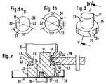
- Fig. 1
- einen Schnitt durch einen erfindungsgemäßen Formfinger;
- Fig. 2
- eine Seitenansicht eines erfindungsgemäßen Formfingers mit einer Auflage; und
- Fig. 3
- einen Schnitt durch den Formfinger gemäß Figur 2 entlang der Linie IV-IV während eines Formprozesses.
- Fig. 1
- a section through a form finger according to the invention;
- Fig. 2
- a side view of a shaped finger according to the invention with a pad; and
- Fig. 3
- a section through the molding finger according to Figure 2 along the line IV-IV during a molding process.
In Fig. 1a ist ein erfindungsgemäßer Formfinger dargestellt. Dieser Formfinger 11 ist ein Teil aus einer ursprünglich zylindrischen Form 30, an der ca. 40 % des hinteren Bereiches 31 und je ca. 7 % der seitlichen Bereiche 32 (die Prozentangaben beziehen sich auf den ursprünglichen Durchmesser der zylindrischen Form 30) abgefräst wurden. Hierdurch ist ein Zylinderausschnitt entstanden, wie er in Figur 1a im Querschnitt dargestellt ist. Dieser Formfinger 11 hat einen Kreisabschnittsbereich 33, der noch die ursprüngliche Aufgabe des Formfingers hat, nämlich die Glättung und Unterstützung (Formung) des Inneren der zu formenden Mündung.A shaped finger according to the invention is shown in FIG. 1a. This
Der Kreisabschnittsbereich 33 überdeckt einen Winkel von ca. 130°, an dem die Formrolle 29 ansetzen und formen kann. Entsprechend dem Winkel von 130° hat der Kreisabschnittsbereich 33 eine Bogenlänge von 2.r. π. 130°/360°, wobei r der Radius des Kreisabschnittsbereiches ist. An den übrigen Seiten des Formfingers 11 kann keine Formung mehr erfolgen, dieser Formfinger 11 ist daher nur zur Anwendung in Fläschchenmaschinen mit einer Formrolle je Formstation (wie z.B. in Figur 1 dargestellt) bestimmt.The
Der vom Kreisabschnittsbereich 33 überdeckte Bereich von ca. 130° eines Vollzylinders richtet sich nach den konstruktiven Gegebenheiten einer jeweils verwendeten Fläschchenmaschine bzw. Formstation.The area of approx. 130 ° of a full cylinder covered by the
Soll eine Formung am Formfinger über 180° oder mehr möglich sein, so ist an einem Vollzylinder nur der hintere Bereich 31 abzunehmen. Normalerweise ist jedoch ein Kreisabschnittsbereich 33 von weniger als 180° ausreichend und auch wünschenswert, da durch die Abnahme des hinteren Bereichs 31 und der seitlichen Bereiche 32 der Querschnitt des Formfingers so verkleinert ist, daß er leicht und sogar ohne Berührung des Innenumfanges einer fertig geformten Mündung aus dieser herausgezogen werden kann.If it is to be possible to shape the molding finger by 180 ° or more, only the rear area 31 is to be removed from a solid cylinder. Normally, however, a
Figur 1b zeigt einen Formfinger 11, dessen Querschnitt eine D2h-Symmetrie hat. Gegenüber der zylindrischen Form 30 sind nur die seitlichen Bereiche 32 freigefräst. Dieser Formfinger 11 hat zwei Kreisabschnittsbereiche 33 mit einem Winkel von jeweils ca. 135° und wird bei einer Formung mit zwei Formrollen oder bei einer (unten beschriebenen) beweglichen Lagerung des Formfingers verwendet.Figure 1b shows a shaped
Am unteren Ende des Formfingers 11 kann, wie in Figur 2 dargestellt, eine Auflage 34 für einen zu formenden Mündungsrand vorgesehen sein. Diese Auflage 34 hat im wesentlichen die Form einer zylindrischen Scheibe 35 mit größerem Durchmesser als die zylindrische Form 30 und ist konzentrisch zu dieser angeordnet. Die zylindrische Scheibe 35 hat unterhalb des Kreisabschnittsbereiches 33 eine Aussparung 36, die einen Freiraum für die Formrolle 29 bildet, so daß diese hier näher an den Formfinger 11 dringen kann, als es das Nennmaß des Rollrandaußendurchmessers eines zu formenden Fläschchens ist.At the lower end of the shaping
Eine solche Situation ist in Figur 3 dargestellt. Die zylindrische Scheibe 35 ist bei 37 (z.B. mittels einer Schraube) an einem Kolben 10 befestigt. Zwischen dem Kolben 10 und der zylindrischen Scheibe 35 ist eine Ölauffangwanne 38 angeordnet, die über den Formfinger 11 gesprühtes Formöl auffängt und über einen Abfluß 39 zurückleitet.Such a situation is shown in FIG. 3. The
Die Auflage 34 hat eine zum Zentrum des Formfingers hin abfallende Oberfläche 40, die den oberen Rand einer Fläschchenmündung 41 formt. Die Anschrägung hat einen Winkel von 5° und richtet sich nach dem jeweiligen Verwendungszweck des herzustellenden Fläschchens.The
Das Formöl kann über den gesamten Formfinger 11 und die zylindrische Scheibe 35 ablaufen, oder aber auch über Kanäle 42 durch die zylindrische Scheibe hindurch abgeleitet werden.The molding oil can run off over the
Während eines Formvorganges wird das gedrehte Glasrohr 5 mittels der Formrolle 29 an seinem Ende 25 gegen den Kreisabschnittsbereichs 33 des Formfingers 11 gedrückt. Die Formrolle 29 weist an ihrem Rand ein Profil 43 auf, dessen nach außen stehender Teil 44 das Glasrohrende 25 gegen den Kreisabschnittsbereich 33 drückt und dabei einen Fläschchenhals 45 formt. Vor einem nach innen stehenden Teil 46 des Profils 43 bildet sich dabei ein etwas dickerer Glaswulst, der in Kontakt mit dem Kreisabschnittsbereich 33 und der schrägen Oberfläche 40 zu einem Bördel- oder Rollrand 47 geformt wird. Bei diesem Formvorgang kann die Formrolle 29 im Bereich der Aussparung 36 etwas näher an den Formfinger 11 dringen, so daß ein kleiner Glasposten 48 in den durch die Aussparung 36 gebildeten freien Raum gedrückt wird. Hierdurch wird gleichzeitig das Nennmaß des Rollrandaußendurchmessers etwas kleiner. Durch das Drehen des Glasrohres 5 wird dieser kleine Glasposten 48 jedoch aus dem Bereich der Aussparung 36 herausgedreht und dabei auf der schrägen Oberfläche 40 glattgebügelt. Durch diese Maßnahme wird erreicht, daß auch bei leicht schwankenden Glasrohrstärken immer eine saubere Mündungsformung gewährleistet ist. Mit der Aussparung 36 wird außerdem erreicht, daß die Formrolle 29 nicht gegen den äußeren Rand der zylindrischen Scheibe 35 gedrückt wird, wobei die Lagerung oder Halterung entweder des Formfingers 11 oder der Formscheibe 29 beschädigt werden könnte.During a molding process, the turned glass tube 5 is pressed against the
Für besondere Ausgestaltungen einer Fläschchenmündung kann am oberen Ende des Formfingers 11 ein erweiterter Rand 49 oder Kragen vorgesehen sein, der in dem Fläschchenhals 45 eine Hinterschneidung formt. Dieser Formfinger 11 muß nach der Formung entweder radial versetzt oder schräg aus der fertig geformten Fläschchenmündung 41 herausgezogen werden. Ein solches Herausziehen des Formfingers ist auch sinnvoll, wenn kein erweiterter Rand 49 vorgesehen ist, da hierbei der Kreisabschnittsbereich 33 ohne Berührung der Innenwandung der Mündung aus dieser genommen wird.For special configurations of a vial mouth, an enlarged rim 49 or collar can be provided at the upper end of the shaping
Ein solches Herausziehen des Formfingers 11 ist nur mit einem Formfinger, wie er in den Figuren 1a, 2 und 3 dargestellt ist, möglich. Der bisher verwendete vollzylindrische Formfinger kann nur in Längsrichtung des Glasrohres aus der fertig geformten Mündung gezogen werden.Such extraction of the
Um die vorteilhafte Gestalt des erfindungsgemäßen Formfingers zu erhalten, kann auch anders als dargestellt der hintere Bereich und die seitlichen Bereiche z.B. in der Art eines Ovals abgetragen werden. Dabei sollte eine möglichst große Querschnittsfläche des Formfingers bestehen bleiben, damit die am Kreisabschnittsbereich aufgenommene Wärme schnell abgeführt werden kann.In order to maintain the advantageous shape of the shaping finger according to the invention, the rear area and the lateral areas, e.g. be removed in the manner of an oval. The largest possible cross-sectional area of the forming finger should remain so that the heat absorbed at the circular section area can be dissipated quickly.
Claims (8)
Applications Claiming Priority (3)
| Application Number | Priority Date | Filing Date | Title |
|---|---|---|---|
| DE4028823 | 1990-09-11 | ||
| DE4028823A DE4028823C2 (en) | 1990-09-11 | 1990-09-11 | Device and form finger for forming a mouth area on a glass vial |
| EP91113745A EP0475112B1 (en) | 1990-09-11 | 1991-08-16 | Apparatus for making the neck of a small glass bottle |
Related Parent Applications (2)
| Application Number | Title | Priority Date | Filing Date |
|---|---|---|---|
| EP91113745.3 Division | 1991-08-16 | ||
| EP91113745A Division-Into EP0475112B1 (en) | 1990-09-11 | 1991-08-16 | Apparatus for making the neck of a small glass bottle |
Publications (2)
| Publication Number | Publication Date |
|---|---|
| EP0678481A2 true EP0678481A2 (en) | 1995-10-25 |
| EP0678481A3 EP0678481A3 (en) | 1995-11-22 |
Family
ID=6414041
Family Applications (2)
| Application Number | Title | Priority Date | Filing Date |
|---|---|---|---|
| EP91113745A Expired - Lifetime EP0475112B1 (en) | 1990-09-11 | 1991-08-16 | Apparatus for making the neck of a small glass bottle |
| EP95109973A Ceased EP0678481A2 (en) | 1990-09-11 | 1991-08-16 | Formfinger for forming a lip to a glass vial |
Family Applications Before (1)
| Application Number | Title | Priority Date | Filing Date |
|---|---|---|---|
| EP91113745A Expired - Lifetime EP0475112B1 (en) | 1990-09-11 | 1991-08-16 | Apparatus for making the neck of a small glass bottle |
Country Status (6)
| Country | Link |
|---|---|
| US (1) | US5252115A (en) |
| EP (2) | EP0475112B1 (en) |
| JP (1) | JPH04231333A (en) |
| CA (1) | CA2051184A1 (en) |
| DE (2) | DE4028823C2 (en) |
| ES (1) | ES2083492T3 (en) |
Families Citing this family (10)
| Publication number | Priority date | Publication date | Assignee | Title |
|---|---|---|---|---|
| DE102004014170B3 (en) * | 2004-03-17 | 2005-10-27 | Ambeg - Dr. J. Dichter Gmbh | Glass processing machine and control method therefor |
| JP5238255B2 (en) * | 2004-09-30 | 2013-07-17 | ベクトン・ディキンソン・アンド・カンパニー | Method for reducing or removing residues in glass containers and glass containers manufactured according to the same |
| DE102016123865A1 (en) | 2016-12-08 | 2018-06-14 | Schott Ag | Process for the further processing of a glass tube semifinished product including a thermal deformation |
| DE102016124833A1 (en) | 2016-12-19 | 2018-06-21 | Schott Ag | Method for producing a hollow glass product from a glass tube semifinished product with markings, as well as uses thereof |
| DE102016125129A1 (en) | 2016-12-21 | 2018-06-21 | Schott Ag | A method for producing a glass tube semi-finished product or a hollow glass product produced therefrom with markings, as well as uses thereof |
| US11186513B2 (en) | 2017-11-30 | 2021-11-30 | Corning Incorporated | Systems and methods for minimizing SHR from pharmaceutical part converting using negative pressure evacuation |
| US11339079B2 (en) | 2017-11-30 | 2022-05-24 | Corning Incorporated | Systems and methods for minimizing SHR from pharmaceutical part converting using pulsed ejection |
| US11420893B2 (en) | 2017-11-30 | 2022-08-23 | Corning Incorporated | Systems and methods for minimizing SHR from piercing during pharmaceutical part converting using a gas flow |
| US10968133B2 (en) | 2017-11-30 | 2021-04-06 | Corning Incorporated | Methods for minimizing SHR in glass articles by producing a gas flow during pharmaceutical part converting |
| DE102018126053A1 (en) * | 2018-10-19 | 2020-04-23 | Schott Schweiz Ag | Process and device for hot forming glass workpieces and hot-formed glass containers |
Citations (4)
| Publication number | Priority date | Publication date | Assignee | Title |
|---|---|---|---|---|
| CA581053A (en) | 1959-08-11 | C. Kahle Louis | Method and apparatus for producing glass articles | |
| DE1596410A1 (en) | 1966-11-29 | 1971-04-01 | Dichter Jakob Dr Ing C H | Machine for manufacturing articles from thermoplastic material, in particular glass |
| DE1796100A1 (en) | 1968-08-30 | 1972-02-24 | Dichter Hans Joachim | Device for forming bottle necks |
| DE3613212C1 (en) | 1986-04-17 | 1987-07-02 | Dichter Hans Joachim | Device for shaping the neck of glass bottles made from glass tubes |
Family Cites Families (8)
| Publication number | Priority date | Publication date | Assignee | Title |
|---|---|---|---|---|
| US416559A (en) * | 1889-12-03 | beady | ||
| US1006383A (en) * | 1910-12-29 | 1911-10-17 | Robert Johns | Neck-grooving attachment for bottle-molding machines. |
| US1229028A (en) * | 1913-09-06 | 1917-06-05 | Louis Naglee Bruner | Apparatus for use in the manufacture of glass bottles and the like. |
| US3449105A (en) * | 1966-03-11 | 1969-06-10 | Corning Glass Works | Flexible shaping tool |
| US4284447A (en) * | 1976-02-20 | 1981-08-18 | Dickens Luther I | Method of manufacturing a composite panel |
| IT1120161B (en) * | 1979-11-27 | 1986-03-19 | Ermanno Vertova | METHOD AND MACHINE FOR FORMING VIALS OBTAINED FROM GLASS TUBE |
| US4441908A (en) * | 1981-03-30 | 1984-04-10 | Owens-Illinois, Inc. | Vial tooling apparatus |
| CH663408A5 (en) * | 1984-03-02 | 1987-12-15 | Owens Illinois Inc | Machine for working regions of preforms made of thermoplastic material |
-
1990
- 1990-09-11 DE DE4028823A patent/DE4028823C2/en not_active Expired - Fee Related
-
1991
- 1991-08-16 ES ES91113745T patent/ES2083492T3/en not_active Expired - Lifetime
- 1991-08-16 DE DE59107422T patent/DE59107422D1/en not_active Expired - Fee Related
- 1991-08-16 EP EP91113745A patent/EP0475112B1/en not_active Expired - Lifetime
- 1991-08-16 EP EP95109973A patent/EP0678481A2/en not_active Ceased
- 1991-09-10 US US07/756,845 patent/US5252115A/en not_active Expired - Fee Related
- 1991-09-11 CA CA002051184A patent/CA2051184A1/en not_active Abandoned
- 1991-09-11 JP JP3258688A patent/JPH04231333A/en active Pending
Patent Citations (4)
| Publication number | Priority date | Publication date | Assignee | Title |
|---|---|---|---|---|
| CA581053A (en) | 1959-08-11 | C. Kahle Louis | Method and apparatus for producing glass articles | |
| DE1596410A1 (en) | 1966-11-29 | 1971-04-01 | Dichter Jakob Dr Ing C H | Machine for manufacturing articles from thermoplastic material, in particular glass |
| DE1796100A1 (en) | 1968-08-30 | 1972-02-24 | Dichter Hans Joachim | Device for forming bottle necks |
| DE3613212C1 (en) | 1986-04-17 | 1987-07-02 | Dichter Hans Joachim | Device for shaping the neck of glass bottles made from glass tubes |
Also Published As
| Publication number | Publication date |
|---|---|
| US5252115A (en) | 1993-10-12 |
| EP0678481A3 (en) | 1995-11-22 |
| DE4028823C2 (en) | 1994-07-07 |
| CA2051184A1 (en) | 1992-03-12 |
| JPH04231333A (en) | 1992-08-20 |
| EP0475112A2 (en) | 1992-03-18 |
| DE4028823A1 (en) | 1992-03-12 |
| EP0475112B1 (en) | 1996-02-21 |
| EP0475112A3 (en) | 1993-01-20 |
| DE59107422D1 (en) | 1996-03-28 |
| ES2083492T3 (en) | 1996-04-16 |
Similar Documents
| Publication | Publication Date | Title |
|---|---|---|
| EP0553609B1 (en) | Method for injection moulding of objects consisting of at least two parts | |
| DE4028824C1 (en) | ||
| EP0630734B1 (en) | Method for demoulding of injection moulded hollow bodies with undercuts on the internal contour and corresponding core | |
| WO1991015349A2 (en) | Device for manufacturing tubes | |
| DE2142570A1 (en) | Device for forming parts to be sintered | |
| DE1527947A1 (en) | Method and device for manufacturing and processing cup-shaped workpieces | |
| EP0678481A2 (en) | Formfinger for forming a lip to a glass vial | |
| DE3623099C2 (en) | Blow molding machine | |
| DE69927732T2 (en) | Gear with integrated clutch teeth and its manufacture | |
| DE2609651C2 (en) | Molding tool for molten gas | |
| WO2000061317A1 (en) | Method of producing homokinetic joints | |
| EP1377424B1 (en) | Method of shaping thermoplastic material | |
| EP1480801B1 (en) | Method for producing a manhole ring and upper sleeve for producing said manhole ring | |
| DE10014611C1 (en) | Injection molding tool and method for producing an inner molded part thereof | |
| DE19629538A1 (en) | Manufacture of ring-shaped flanged workpieces | |
| AT522681B1 (en) | Upper part for a spice grinder | |
| DE2947906C2 (en) | Pressure forming device | |
| DE2209166C3 (en) | Injection mold for the production of injection-molded parts with thread profiles arranged on part of the circumferential surface of a bore | |
| EP4292789A1 (en) | Pressure die casting mold | |
| AT401254B (en) | Injection mould for producing a guarantee closure for containers | |
| DE2835784B1 (en) | Pot shape, especially for the production of glass objects | |
| DE3112136A1 (en) | Tool for internally supporting the bed of a one-piece drop base rim | |
| DE3444298A1 (en) | Mould for producing glass objects by a centrifugal process | |
| DE1266951B (en) | Translucent, circumferentially closed hollow body as well as method and device for manufacturing this body | |
| AT217649B (en) | Device for the production of glass flakes |
Legal Events
| Date | Code | Title | Description |
|---|---|---|---|
| PUAI | Public reference made under article 153(3) epc to a published international application that has entered the european phase |
Free format text: ORIGINAL CODE: 0009012 |
|
| PUAL | Search report despatched |
Free format text: ORIGINAL CODE: 0009013 |
|
| 17P | Request for examination filed |
Effective date: 19950807 |
|
| AC | Divisional application: reference to earlier application |
Ref document number: 475112 Country of ref document: EP |
|
| AK | Designated contracting states |
Kind code of ref document: A2 Designated state(s): BE CH DE ES FR GB IT LI |
|
| AK | Designated contracting states |
Kind code of ref document: A3 Designated state(s): BE CH DE ES FR GB IT LI |
|
| RAP1 | Party data changed (applicant data changed or rights of an application transferred) |
Owner name: CARL-ZEISS-STIFTUNG TRADING AS SCHOTT GLASWERKE Owner name: SCHOTT GLAS |
|
| RAP1 | Party data changed (applicant data changed or rights of an application transferred) |
Owner name: CARL-ZEISS-STIFTUNG TRADING AS SCHOTT GLAS Owner name: SCHOTT GLAS |
|
| GRAG | Despatch of communication of intention to grant |
Free format text: ORIGINAL CODE: EPIDOS AGRA |
|
| 17Q | First examination report despatched |
Effective date: 19980826 |
|
| STAA | Information on the status of an ep patent application or granted ep patent |
Free format text: STATUS: THE APPLICATION HAS BEEN REFUSED |
|
| 18R | Application refused |
Effective date: 19990222 |