EP0678386A2 - Druckkopf, Drucker und Druckverfahren mit diesem Druckkopf - Google Patents
Druckkopf, Drucker und Druckverfahren mit diesem Druckkopf Download PDFInfo
- Publication number
- EP0678386A2 EP0678386A2 EP95302634A EP95302634A EP0678386A2 EP 0678386 A2 EP0678386 A2 EP 0678386A2 EP 95302634 A EP95302634 A EP 95302634A EP 95302634 A EP95302634 A EP 95302634A EP 0678386 A2 EP0678386 A2 EP 0678386A2
- Authority
- EP
- European Patent Office
- Prior art keywords
- printing
- printing head
- signal
- accordance
- count value
- Prior art date
- Legal status (The legal status is an assumption and is not a legal conclusion. Google has not performed a legal analysis and makes no representation as to the accuracy of the status listed.)
- Granted
Links
Images


Classifications
-
- B—PERFORMING OPERATIONS; TRANSPORTING
- B41—PRINTING; LINING MACHINES; TYPEWRITERS; STAMPS
- B41J—TYPEWRITERS; SELECTIVE PRINTING MECHANISMS, i.e. MECHANISMS PRINTING OTHERWISE THAN FROM A FORME; CORRECTION OF TYPOGRAPHICAL ERRORS
- B41J2/00—Typewriters or selective printing mechanisms characterised by the printing or marking process for which they are designed
- B41J2/005—Typewriters or selective printing mechanisms characterised by the printing or marking process for which they are designed characterised by bringing liquid or particles selectively into contact with a printing material
- B41J2/01—Ink jet
- B41J2/015—Ink jet characterised by the jet generation process
- B41J2/04—Ink jet characterised by the jet generation process generating single droplets or particles on demand
- B41J2/045—Ink jet characterised by the jet generation process generating single droplets or particles on demand by pressure, e.g. electromechanical transducers
- B41J2/04501—Control methods or devices therefor, e.g. driver circuits, control circuits
- B41J2/04541—Specific driving circuit
-
- B—PERFORMING OPERATIONS; TRANSPORTING
- B41—PRINTING; LINING MACHINES; TYPEWRITERS; STAMPS
- B41J—TYPEWRITERS; SELECTIVE PRINTING MECHANISMS, i.e. MECHANISMS PRINTING OTHERWISE THAN FROM A FORME; CORRECTION OF TYPOGRAPHICAL ERRORS
- B41J2/00—Typewriters or selective printing mechanisms characterised by the printing or marking process for which they are designed
- B41J2/005—Typewriters or selective printing mechanisms characterised by the printing or marking process for which they are designed characterised by bringing liquid or particles selectively into contact with a printing material
- B41J2/01—Ink jet
- B41J2/015—Ink jet characterised by the jet generation process
- B41J2/04—Ink jet characterised by the jet generation process generating single droplets or particles on demand
- B41J2/045—Ink jet characterised by the jet generation process generating single droplets or particles on demand by pressure, e.g. electromechanical transducers
- B41J2/04501—Control methods or devices therefor, e.g. driver circuits, control circuits
- B41J2/04543—Block driving
-
- B—PERFORMING OPERATIONS; TRANSPORTING
- B41—PRINTING; LINING MACHINES; TYPEWRITERS; STAMPS
- B41J—TYPEWRITERS; SELECTIVE PRINTING MECHANISMS, i.e. MECHANISMS PRINTING OTHERWISE THAN FROM A FORME; CORRECTION OF TYPOGRAPHICAL ERRORS
- B41J2/00—Typewriters or selective printing mechanisms characterised by the printing or marking process for which they are designed
- B41J2/005—Typewriters or selective printing mechanisms characterised by the printing or marking process for which they are designed characterised by bringing liquid or particles selectively into contact with a printing material
- B41J2/01—Ink jet
- B41J2/015—Ink jet characterised by the jet generation process
- B41J2/04—Ink jet characterised by the jet generation process generating single droplets or particles on demand
- B41J2/045—Ink jet characterised by the jet generation process generating single droplets or particles on demand by pressure, e.g. electromechanical transducers
- B41J2/04501—Control methods or devices therefor, e.g. driver circuits, control circuits
- B41J2/0458—Control methods or devices therefor, e.g. driver circuits, control circuits controlling heads based on heating elements forming bubbles
Definitions
- This invention relates to a printing head, and a printer and printing method using the printing head and, more particularly, to a printer which performs printing by forming droplets and discharging the droplets onto a printing medium, and especially uses a printing head which performs printing by giving a thermal effect to a liquid to boil the liquid so as to form droplets, and discharging the droplets onto a printing medium, and a printing method using the printing head.
- the printing head of such a printer normally has an arrangement in which a plurality of printing elements, and a driving integrated circuit which can concurrently drive a predetermined number of printing elements as one block are mounted on a single board.
- a printing medium a paper sheet, cloth, plastic sheet, or the like.
- an ink-jet printer which performs low-noise and non-impact printing by discharging an ink from discharge nozzles arranged on printing elements, can achieve high-density, high-speed printing.
- the ink-jet printer is utilized in information processing systems as printers serving as output terminals of a copying machine, facsimile apparatus, printer, word processor, work station, and the like, or as a handy or portable printer equipped in a personal computer, host computer, optical disk apparatus, video apparatus, and the like, and is commercially available.
- Such a printer comprises printing means (printing head), transfer means for transferring a printing medium, driving means for reciprocally scanning the printing head in a direction perpendicular to the transfer direction of the printing medium, and control means for controlling ink discharge from the printing head, and the transfer and driving means.
- the apparatus employs a printing method for serially scanning the printing head for discharging ink droplets from a plurality of discharge nozzles in the direction (main scanning direction) perpendicular to the transfer direction of the printing medium, and intermittently transferring the printing medium by a transfer amount equal to the printing width upon printing.
- This printing method achieves printing by discharging an ink onto a printing medium in accordance with a printing signal, and is popularly used as a low-noise printing method with low running cost.
- printing can be achieved with a width corresponding to the number of nozzles each time the printing head scans the printing medium, thus attaining high-speed printing.
- function elements e.g., transistors
- a logic circuit for drive-controlling these function elements and the function elements are integrated in the same board.
- Fig. 9 is a block diagram showing the circuit arrangement of a conventional printing head having a 128-bit printing element, which can perform printing for 128 pixels (one pixel corresponds to 1 bit) in the transfer direction of a printing medium in a single printing operation.
- reference numeral 31 denotes a 128-bit shift register; 32, a 128-bit latch; 33, a 128-bit transistor array for driving a heat-generating element group; 34, a heat-generating element group including 128 heat-generating resistors (R1 to R128); and 35, a gate circuit including 128 AND gates.
- Reference symbol V H denotes an applied voltage to be applied to the heat-generating element group 34.
- Signals to be input to the printing head include signals LAT (data latch signal), DATA (image signal for 128 pixels), and CLK (clock signal) as image-related signals, and signals STRB (strobe signal), HEATA, HEATB, HEATC, and HEATD as driving-related signals.
- LAT data latch signal
- DATA image signal for 128 pixels
- CLK clock signal
- STRB strobe signal
- Fig. 10 is a timing chart showing the driving sequence of the printing head shown in Fig. 9. Reference symbols denoting various signals shown in Fig. 10 correspond to those used in Fig. 9.
- Fig. 11 is a block diagram showing the circuit arrangement of a conventional printing head having a 64-bit printing element group, which can perform printing for 64 pixels (1 pixel corresponds to 1 bit) in the transfer direction of a printing medium in a single printing operation.
- reference numeral 41 denotes a 64-bit shift register; 42, a 64-bit latch; 43, a 64-bit transistor array; 44, a heat-generating element group including 64 heat-generating resistors (R1 to R64); 45, a gate circuit including 64 AND gates; and 46, a block selection circuit for selecting one of eight blocks to be described below.
- Reference symbol RESET denotes a reset signal; and BLOCKENB1, BLOCKENB2, and BLOCKENB3, signals for indicating one to be enabled of the eight blocks. Other signals are the same as those in Fig. 9.
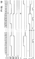
- Fig. 12 is a timing chart showing the driving sequence of the printing head shown in Fig. 11. Reference symbols denoting various signals shown in Fig. 12 correspond to those used in Fig. 11.
- the arrangement shown in Fig. 11 is substantially the same as that shown in Fig. 9, except for the number of pixels printed in the transfer direction of the printing medium.
- the 64 heat-generating resistors R1 to R64
- the 64 heat-generating resistors B1 to B8).
- the arrangement shown in Fig. 11 also comprises shift registers and latches corresponding in number to the heat-generating elements on a single board so as to drive the plurality of heat-generating resistors.
- the entire printing head is controlled using a latch signal and a plurality of enable signals (BLOCKENB1 to BLOCKENB3) independent from other control signals.
- the printing head undesirably has a large size, and the thickness of a flexible print board for supplying signals to the head increases in proportion to the number of signals, thus increasing cost. Furthermore, an increase in the number of signal lines, i.e., an increase in the number of line connections causes low reliability of the apparatus.
- the four signals HEATA, HEATB, HEATC, and HEATD must be supplied from a circuit outside the printing head as signals for selecting the heat-generating elements divided into groups.
- a plurality of enable signals (BLOCKENB1 to BLOCKENB3) must also be supplied from a circuit outside the printing head as signals for selecting the heat-generating resistors divided into groups.
- a printing head in which a plurality of printing elements are divided into a plurality of groups, including the plurality of transducers for driving the plurality of printing elements in each group unit, sending an electric current to each divided group of the plurality of transducers in accordance with printing data, comprising: counter means for counting an input clock signal; instruction signal generation means for generating an instruction signal which instructs to drive the printing elements corresponding to one of the plurality of divided groups on the basis of a count value output from said counter means; latch means for latching printing data for a predetermined number of pixels; and electric current sending means for sending the electric current to the transducers corresponding to one of the plurality of divided groups in accordance with the printing data latched by the latch means, and the instruction signal.
- a printer for printing an image on a printing medium by electrically driving the above-mentioned printing head comprising: input means for inputting image data from an external unit; storage means for temporarily storing the image data input by the input means; transmission means for transmitting printing data and a clock signal in accordance with the image data stored in the storage means; first supply means for supplying a strobe signal for supplying an electric current to the printing head and driving the transducers of the printing head, to the printing head at a predetermined interval; and second supply means for supplying a reset signal to reset a count value of the counter means, included in the printing head, for counting the clock signal.
- the foregoing object is attained by providing a printing method of printing an image on a printing medium by electrically driving the above-mentioned printing head, comprising: an input step of inputting image data from an external unit; a storage step of temporarily storing the image data input in the input step in a storage medium; a reset step of supplying a reset signal to reset a count value of the counter means, included in the printing head, for counting the transmission clock; a transmission step of transmitting printing data and a clock for the image signal in accordance with the image data stored in the storage medium; and a supply step of supplying a strobe signal for supplying an electric current to the printing head and driving the electrothermal transducers of the printing head, to the printing head at a predetermined interval.
- the printing head generates an instruction signal for instructing driving of the printing elements corresponding to one of the plurality of groups on the basis of a count value obtained by counting input clock signals, and latches an input image signal for a predetermined number of pixels.
- the printing head sends an electric current to the electrothermal transducers corresponding to one of the plurality of groups in accordance with the latched image signal and the instruction signal.
- image data is input from an external device, and the input image data is temporarily stored.
- An image signal and transmission clocks of the image signal are transmitted to the printing head in accordance with the stored image data, and strobe signals for sending an electrical current to the electrothermal transducers of the printing head to drive them are supplied to the printing head at predetermined intervals.
- a reset signal is supplied to reset the count value of the counter means, included in the printing head, for counting the number of transmission clocks.
- image data is input from an external device, and the input image data is temporarily stored in a storage medium.
- a reset signal is supplied to reset the count value of the counter, included in the printing head, for counting the number of clocks, and an image signal and transmission clocks of the image signal are transmitted to the printing head in accordance with the image data stored in the storage medium.
- strobe signals for sending an electrical current to the electrothermal transducers of the printing head to drive them are supplied to the printing head at predetermined intervals.
- the invention is particularly advantageous since the printing operation and control of the printing head can be realized while the number of signals to be supplied to the printing head is reduced, and signals required for controlling the printing head are generated by a simple internal circuit of the printing head on the basis of supplied signals.
- the number of signal lines for connecting an external device for supplying signals to the printing head, and the printing head can be reduced, the number of signal input terminals provided to the printing head can be reduced, thus contributing to size reduction and cost reduction of the printing head.
- the printing head can be controlled by a smaller number of signal lines, the control operation in the printer which incorporates with the printing head can be simplified.
- the number of signal lines for connecting the printer and the printing head can also be reduced, an improvement in reliability of the apparatus and cost reduction can be realized.
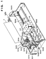
- Fig. 1 is a perspective view showing the outer appearance of an ink-jet printer IJRA as a typical embodiment of the present invention.
- a carriage HC engages with a spiral groove 5004 of a lead screw 5005, which rotates via driving force transmission gears 5009 to 5011 upon forward/reverse rotation of a driving motor 5013.
- the carriage HC has a pin (not shown), and is reciprocally scanned in the directions of arrows a and b in Fig. 1.
- An integrated ink-jet cartridge IJC which incorporates a printing head IJH and an ink tank IT is mounted on the carriage HC.
- Reference numeral 5002 denotes a sheet pressing plate, which presses a paper sheet against a platen 5000, ranging from one end to the other end of the scanning path of the carriage.
- Reference numerals 5007 and 5008 denote photocouplers which serve as a home position detector for recognizing the presence of a lever 5006 of the carriage in a corresponding region, and used for switching, e.g., the rotating direction of the motor 5013.
- Reference numeral 5016 denotes a member for supporting a cap member 5022, which caps the front surface of the printing head IJH; and 5015, a suction device for sucking ink residue through the interior of the cap member.
- the suction device 5015 performs suction recovery of the printing head via an opening 5023 of the cap member 5015.
- Reference numeral 5017 denotes a cleaning blade; 5019, a member which allows the blade to be movable in the back-and-forth direction of the blade. These members are supported on a main unit support plate 5018. The shape of the blade is not limited to this, but a known cleaning blade can be used in this embodiment.
- Reference numeral 5021 denotes a lever for initiating a suction operation in the suction recovery operation. The lever 5021 moves upon movement of a cam 5020, which engages with the carriage, and receives a driving force from the driving motor via a known transmission mechanism such as clutch switching.
- the capping, cleaning, and suction recovery operations are performed at their corresponding positions upon operation of the lead screw 5005 when the carriage reaches the home-position side region.
- the present invention is not limited to this arrangement as long as desired operations are performed at known timings.
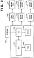
- Fig. 2 is a block diagram showing the arrangement of a control circuit of the ink-jet printer IJRA.
- reference numeral 1700 denotes an interface for inputting a printing signal (image signal) from an external device; 1701, an MPU; 1702, a ROM for storing a control program executed by the MPU 1701; and 1703, a DRAM for storing various data (the printing signal, printing data supplied to the printing head, and the like).
- Reference numeral 1704 denotes a gate array (G.A.) for performing supply control of printing data to the printing head IJH.
- the gate array 1704 also performs data transfer control among the interface 1700, the MPU 1701, and the RAM 1703.
- Reference numeral 1710 denotes a carrier motor for transferring the printing head IJH; and 1709, a transfer motor for transferring a printing sheet.
- Reference numeral 1705 denotes a head driver for driving a head; and 1706 and 1707, motor drivers for driving the transfer motor 1709 and the carrier motor 1710.
- the printing signal is converted into printing data for a printing operation between the gate array 1704 and the MPU 1701.
- the motor drivers 1706 and 1707 are driven, and the printing head IJH is driven in accordance with the printing data supplied to the head driver 1705, thus performing the printing operation.
- four signal lines are supplied from the head driver 1705 to the printing head IJH, and the printing head IJH is driven by the following four signals ((1) image signal (DATA), (2) clock signal (CLK), (3) reset signal (RESET), (4) strobe signal (STRB)) supplied via these signal lines, and an applied voltage V H to the printing head.
- the supply timings of these signals to the printing head IJH are controlled by the MPU 1701.
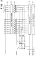
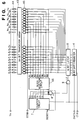
- Fig. 3 is a block diagram showing the circuit arrangement of the printing head IJH according to this embodiment.
- This circuit is arranged on a single circuit board, and this printing head can perform a printing operation for 128 pixels in the transfer direction of a printing medium in a single printing operation.
- input signals associated with an image signal include signals CLK (clock), DATA, and RESET, and a signal STRB is a strobe signal.
- Reference symbol V H denotes an applied voltage to be applied to a heat-generating element group 34.
- the signal DATA is an image signal in units of bits, and is input in synchronism with the signal CLK.
- Reference numeral 11 denotes a counter for counting the signal CLK; 12, a decoder for receiving and decoding output signals C1 and C2 from the counter 11; and 14, a 128-bit latch circuit for latching an output value from a shift register 31 at the timing of the signal RESET.
- 128 nozzles for discharging an ink supplied from an ink cartridge onto a printing medium are arranged on the heat-generating element group 34.
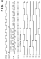
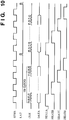
- Fig. 4 is a timing chart showing various signals input to the printing head IJH shown in Fig. 3. As shown in Fig. 4, the total number of clocks of the signal CLK is 128 during a single printing operation, which is equal to the number of heat-generating elements. The 128 clocks are divided into four groups (A), (B), (C), and (D) in units of 32 clocks.
- the signal CLK is controlled by the combination of the counter 11 and the decoder 12, and block selection signals (B1, B2, B3, B4) can be generated.
- the signal RESET is used as an input to the 128-bit latch circuit 14, and is also used as a reset signal of the counter 11.
- the printing operation of the printer IJRA with the printing head of this embodiment will be described below with reference to the flow chart in Fig. 5. Since the printing head of this embodiment can perform a printing operation for 128 pixels in the transfer direction of a printing medium in a single printing operation, the DRAM 1703 in a control unit stores image data for 128 lines accordingly.
- step S10 the DRAM 1703 stores image data for 128 lines. This operation is attained when an information processing apparatus (not shown) such as a work station for supplying data to the printer transmits a predetermined command and its associated data.
- step S15 the count value of the counter 11 is reset, and the signal RESET is supplied to the printing head IJH to latch data from the 128-bit shift register 31 by the 128-bit latch circuit 14.
- step S20 the signal STRB having a predetermined period is supplied to the printing head IJH. This period is determined by the MPU 1701 in consideration of the characteristics of the constituting elements of the apparatus such as the moving speed of the printing head in the carriage scanning direction, the heat-generation characteristics of the heat-generating element group 34, and the like.
- step S25 and S30 the signals CLK and DATA are supplied to the printing head IJH.
- step S35 the number (CNT) of clocks of the signal CLK is counted.
- step S40 it is checked if the value CNT is "128", If YES in step S40, the flow advances to step S55; otherwise, the flow advances to step S45.
- step S45 it is checked if the value CNT is "32, "64", or "96". If the value CNT is one of the above-mentioned three values, the flow advances to step S50, and a signal STRB having the predetermined period is supplied to the printing head IJH. On the other hand, if the value CNT is none of the three values, the flow returns to step S25.
- step S55 the printing head is moved by a predetermined amount in the carriage scanning direction (the direction of the arrow a in Fig. 1).
- step S60 it is checked if the printing head has reached the rightmost end of the carriage scanning path. If NO in step S60, the flow returns to step S15. However, if YES in step S60, the flow advances to step S65, and the printing head is returned to its home position in the direction of the arrow b in Fig. 1.
- step S70 a printing medium (printing sheet) is transferred by a predetermined amount in the transfer direction. Furthermore, it is checked in step S75 if a printing operation for one page is completed. If NO in step S75, the flow returns to step S10, and the DRAM 1703 receives and stores image data for next 128 lines, thus repeating the above-mentioned processing. However, if YES in step S75, the processing ends.
- control for dividing the 128 heat-generating resistors into four blocks, and supplying an electric current to one of these blocks to drive it can be made on the basis of these signals.
- the conventional circuit requires 8 input signals, while this embodiment can reduce the number of input signals to 4. Therefore, a flexible print board for transmitting signals to the printing head can be thinned.
- Fig. 6 is a block diagram showing the circuit arrangement of the printing head IJH according to this embodiment.
- This circuit is arranged on a single circuit board, and this printing head can perform a printing operation for 64 pixels in the transfer direction of a printing medium in a single printing operation.
- the signals input to the circuit of this embodiment are the same as those described in the first embodiment, and a repetitive description thereof will be avoided.
- the same reference numerals in Fig. 6 denote the same parts as in Fig. 11 of the prior art, and a detailed description thereof will be omitted.
- reference numeral 4 denotes an 8-bit shift register for inputting an image signal (DATA) in accordance with a clock signal (CLK); 5, an 8-bit latch circuit for latching the output from the 8-bit shift register 4; 7, a counter circuit for counting the clock signal (CLK); and 8 and 9, gate circuits.
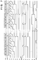
- Fig. 7 is a timing chart showing various signals input to the printing head IJH shown in Fig. 6. As shown in Fig. 6, the total number of clocks of the signal CLK during a single printing operation is "64", which is equal to the number of heat-generating elements. The 64 clocks are divided into 8 groups in units of 8 clocks.
- the ON/OFF state of the output C1 is switched in synchronism with the period of the clock signal (CLK)
- the ON/OFF state of the-output C2 is switched in synchronism with a period 2-fold that of the signal CLK
- the ON/OFF states of the outputs C3, C4, C5, and C6 are respectively switched in synchronism with periods 4-, 8-, 16-, and 32-fold that of the signal CLK.
- the outputs C1, C2, and C3 are input to the gate circuit 8 to generate an internal control signal A1.
- the internal control signal A1 is input to the gate circuit 9 together with the signal CLK to generate another internal control signal LT.
- the signal LT is used as a latch signal for latching an 8-bit image signal.
- the outputs C4, C5, and C6 are input to a block selection circuit 46 to generate block selection signals (B1, B2, B3, B4, B5, B6, B7, B8).
- the latch signal (LT) becomes “1” to latch the image signal
- the signal STRB generates a pulse signal shown in Fig. 4 while the block selection signal B1 is "1".
- the outputs from AND gates corresponding to heat-generating resistors R1, R9, ..., R59 change to "1" to drive a 64-bit transistor array 43 corresponding to these heat-generating resistors, thereby heating the heat-generating resistors.
- each eight heat-generating resistors are heated in units of 8-bit blocks.
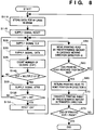
- a printer with the printing head of this embodiment will be described below with reference to the flow chart shown in Fig. 8. Since the printing head of this embodiment can perform a printing operation for 64 pixels in the transfer direction of a printing medium in a single printing operation, the DRAM 1703 of a control unit stores image data for 64 lines accordingly.
- the same step numbers in Fig. 8 denote the same processing steps as in the flow chart of the printing operation according to the first embodiment shown in Fig. 5, and a detailed description thereof will be omitted. In the following description, only characteristic portions of this embodiment will be explained.
- step S110 the DRAM 1703 stores image data for 64 lines. This operation is attained when an information processing apparatus (not shown) such as a work station for supplying data to the printer transmits a predetermined command and its associated data, as in the first embodiment.
- step S115 the signal RESET is supplied to the printing head IJH to reset the count value of the counter circuit 7.
- steps S25 to S35 the same processing as in the first embodiment is performed. It is then checked in step S140 if the number of clocks (value CNT) of the signal CLK is a multiple of 8. If YES in step S140, the flow advances to step S50; otherwise, the flow returns to step S25. After the signal STRB is supplied in step S50, it is then checked in step S150 if the value CNT is "64". If YES in step S150, the flow advances to step S155 to reset CNT; otherwise, the flow returns to step S25.
- processing operations in steps S55 to S75 are executed in the same manner as in the first embodiment.
- the supply timings of the signals RESET and STRB to the printing head IJH can be controlled more easily than in the first embodiment.
- control for dividing the 64 heat-generating resistors into eight blocks and sending an electric current to each of the blocks can be realized on the basis of these signals.
- the latch signal is generated based on the signal CLK and the output from the counter circuit, and control for sending an electric current to the heat-generating resistors can be attained in accordance with the latch signal. For this reason, an image signal with the number of bits equal to the number of heat-generating resistors need neither be stored nor latched, and this embodiment is advantageous since the circuit can be constituted by a simple latch circuit and shift register, which store and latch an image signal with a smaller number of bits.
- the number of pixels (the number of bits) which can be printed in a single printing operation is exemplified as 128 or 64 bits, and the number of divided blocks of the heat-generating resistors is exemplified as 4 or 8 blocks.
- the present invention is not limited to these specific details, but printing heads with other numbers of pixels (numbers of bits) and other numbers of blocks may be used.
- these values are preferably powers of 2 (2 n ).
- the printing head mounted on the ink-jet printer is exemplified.
- the present invention is not limited to this, but may be applied to other printing methods, i.e., printers such as a thermal head printer, a wire-dot printer, and the like, which drive printing elements (heat-generating elements, and the like) by supplying a current.
- a printer which comprises means (e.g., an electrothermal transducer, laser beam generator, and the like) for generating heat energy as energy utilized upon execution of ink discharge, and causes a change in state of an ink by the heat energy, among the ink-jet printers.
- means e.g., an electrothermal transducer, laser beam generator, and the like
- heat energy as energy utilized upon execution of ink discharge
- the system is effective because, by applying at least one driving signal, which corresponds to printing information and gives a rapid temperature rise exceeding film boiling, to each of electrothermal transducers arranged in correspondence with a sheet or liquid channels holding a liquid (ink), heat energy is generated by the electrothermal transducer to effect film boiling on the heat acting surface of the printing head, and consequently, a bubble can be formed in the liquid (ink) in one-to-one correspondence with the driving signal.
- the driving signal is applied as a pulse signal, the growth and shrinkage of the bubble can be attained instantly and adequately to achieve discharge of the liquid (ink) with the particularly high response characteristics.
- signals disclosed in U.S. Patent Nos. 4,463,359 and 4,345,262 are suitable. Note that further excellent printing can be performed by using the conditions described in U.S Patent No. 4,313,124 of the invention which relates to the temperature rise rate of the heat acting surface.
- the arrangement using U.S. Patent Nos. 4,558,333 and 4,459,600 which disclose the arrangement having a heat acting portion arranged in a flexed region is also included in the present invention.
- the present invention can be effectively applied to an arrangement based on Japanese Patent Laid-Open No. 59-123670 which discloses the arrangement using a slot common to a plurality of electrothermal transducers as a discharge portion of the electrothermal transducers, or Japanese Patent Laid-Open No. 59-138461 which discloses the arrangement having an opening for absorbing a pressure wave of heat energy in correspondence with a discharge portion.
- a full line type printing head having a length corresponding to the width of a maximum printing medium which can be printed by the printer, either the arrangement which satisfies the full-line length by combining a plurality of printing heads as disclosed in the above specification or the arrangement as a single printing head obtained by forming printing heads integrally can be used.
- a cartridge type printing head as described in the above embodiment, in which an ink tank is integrally arranged on the printing head itself but also an exchangeable chip type printing head which can be electrically connected to the apparatus main unit and can receive an ink from the apparatus main unit upon being mounted on the apparatus main unit can be applicable to the present invention.
- recovery means for the printing head, preliminary auxiliary means, and the like provided as an arrangement of the printer of the present invention since the printing operation can be further stabilized.
- examples of such means include, for the printing head, capping means, cleaning means, pressurization or suction means, and preliminary heating means using electrothermal transducers, another heating element, or a combination thereof. It is also effective for stable printing to provide a preliminary discharge mode which performs discharge independently of printing.
- a printing mode of the printer not only a printing mode using only a primary color such as black or the like, but also at least one of a multi-color mode using a plurality of different colors or a full-color mode achieved by color mixing can be implemented in the printer either by using an integrated printing head or by combining a plurality of printing heads.
- the ink is liquid.
- the present invention may employ an ink which is solid at room temperature or less and softens or liquefies at room temperature, or an ink which liquefies upon application of a use printing signal, since it is a general practice to perform temperature control of the ink itself within a range from 30°C to 70°C in the ink-jet system, so that the ink viscosity can fall within a stable discharge range.
- an ink which is solid in a non-use state and liquefies upon heating may be used.
- an ink which liquefies upon application of heat energy according to a printing signal and is discharged in a liquid state, an ink which begins to solidify when it reaches a printing medium, or the like, is applicable to the present invention.
- an ink may be situated opposite electrothermal transducers while being held in a liquid or solid state in recess portions of a porous sheet or through holes, as described in Japanese Patent Laid-Open No. 54-56847 or 60-71260.
- the above-mentioned film boiling system is most effective for the above-mentioned inks.
- the ink-jet printer of the present invention may be used in the form of a copying machine combined with a reader, and the like, or a facsimile apparatus having a transmission/reception function in addition to an image output terminal of an information processing equipment such as a computer.
- the present invention can be applied to a system constituted by a plurality of devices, or to an apparatus comprising a single device. Furthermore, it goes without saying that the invention is applicable also to a case where the object of the invention is attained by supplying a program to a system or apparatus.
Landscapes
- Particle Formation And Scattering Control In Inkjet Printers (AREA)
- Electronic Switches (AREA)
Applications Claiming Priority (3)
| Application Number | Priority Date | Filing Date | Title |
|---|---|---|---|
| JP6085103A JPH07290707A (ja) | 1994-04-22 | 1994-04-22 | 記録ヘッド及び該記録ヘッドを用いたプリンタ装置及びプリント方法 |
| JP85103/94 | 1994-04-22 | ||
| JP8510394 | 1994-04-22 |
Publications (3)
| Publication Number | Publication Date |
|---|---|
| EP0678386A2 true EP0678386A2 (de) | 1995-10-25 |
| EP0678386A3 EP0678386A3 (de) | 1998-06-10 |
| EP0678386B1 EP0678386B1 (de) | 2003-02-19 |
Family
ID=13849285
Family Applications (1)
| Application Number | Title | Priority Date | Filing Date |
|---|---|---|---|
| EP95302634A Expired - Lifetime EP0678386B1 (de) | 1994-04-22 | 1995-04-20 | Druckkopf, Drucker und Druckverfahren mit diesem Druckkopf |
Country Status (4)
| Country | Link |
|---|---|
| US (1) | US5790140A (de) |
| EP (1) | EP0678386B1 (de) |
| JP (1) | JPH07290707A (de) |
| DE (1) | DE69529638T2 (de) |
Cited By (8)
| Publication number | Priority date | Publication date | Assignee | Title |
|---|---|---|---|---|
| WO1996032270A1 (en) * | 1995-04-12 | 1996-10-17 | Eastman Kodak Company | Integrated drive circuitry in drop on demand print heads |
| EP0805029A2 (de) * | 1996-04-22 | 1997-11-05 | Canon Kabushiki Kaisha | Substrat für ein Element eines Tintenstrahldruckkopfes, Tintenstrahldruckkopf und Tintenstrahldruckapparat |
| EP0811488A2 (de) * | 1996-06-07 | 1997-12-10 | Canon Kabushiki Kaisha | Aufzeichnungskopf und Aufzeichnungsvorrichtung |
| US5933161A (en) * | 1996-03-21 | 1999-08-03 | Fuji Xerox Co., Ltd. | Ink-jet recorder having a driving circuit for driving heat-generating elements |
| SG89371A1 (en) * | 2000-01-31 | 2002-06-18 | Canon Kk | Printhead, printhead driving method, and data output apparatus |
| US6817703B2 (en) | 2002-01-28 | 2004-11-16 | Benq Corporation | Driving circuit and method for an inkjet printhead |
| EP1502743A1 (de) * | 2002-05-08 | 2005-02-02 | Sony Corporation | Flüssigkeitsausstosskopf, flüssigkeitsausstossvorrichtung und verfahren zum ausstossen von flüssigkeit |
| US7165823B2 (en) | 2000-01-20 | 2007-01-23 | Sony Corporation | Method for driving recording head, recording head, and ink jet printer |
Families Citing this family (20)
| Publication number | Priority date | Publication date | Assignee | Title |
|---|---|---|---|---|
| JP3472005B2 (ja) * | 1995-12-21 | 2003-12-02 | キヤノン株式会社 | 記録装置及び記録制御方法 |
| JP3352331B2 (ja) * | 1996-07-31 | 2002-12-03 | キヤノン株式会社 | 記録ヘッド用基板、記録ヘッド、ヘッドカートリッジ及びその記録ヘッドを用いた記録装置 |
| US6312079B1 (en) | 1999-09-22 | 2001-11-06 | Lexmark International, Inc. | Print head drive scheme for serial compression of I/O in ink jets |
| US6375300B1 (en) * | 2000-01-04 | 2002-04-23 | International Business Machines Corporation | Interleave pulse modulation for thermal printers |
| JP4532646B2 (ja) * | 2000-02-21 | 2010-08-25 | キヤノン株式会社 | プリントヘッドおよびプリント装置 |
| US6398346B1 (en) * | 2000-03-29 | 2002-06-04 | Lexmark International, Inc. | Dual-configurable print head addressing |
| US6905185B2 (en) * | 2000-07-19 | 2005-06-14 | Canon Kabushiki Kaisha | Inkjet printing apparatus, with plural printheads and control circuit |
| US6547356B2 (en) | 2001-02-09 | 2003-04-15 | Lexmark International, Inc. | Latching serial data in an ink jet print head |
| US6712451B2 (en) * | 2002-03-05 | 2004-03-30 | Eastman Kodak Company | Printhead assembly with shift register stages facilitating cleaning of printhead nozzles |
| US6712439B1 (en) | 2002-12-17 | 2004-03-30 | Lexmark International, Inc. | Integrated circuit and drive scheme for an inkjet printhead |
| US7452041B2 (en) * | 2003-08-07 | 2008-11-18 | Lexmark International, Inc. | Ink jet heater chip with internally generated clock signal |
| JP4353526B2 (ja) | 2003-12-18 | 2009-10-28 | キヤノン株式会社 | 記録ヘッドの素子基体及び該素子基体を有する記録ヘッド |
| US8128205B2 (en) | 2005-10-31 | 2012-03-06 | Hewlett-Packard Development Company, L.P. | Fluid ejection device |
| TWI265093B (en) * | 2005-12-29 | 2006-11-01 | Ind Tech Res Inst | Integrated circuit of inkjet print system and control circuit thereof |
| JP2009056732A (ja) * | 2007-08-31 | 2009-03-19 | Ricoh Co Ltd | ヘッド駆動装置 |
| JP5717421B2 (ja) * | 2010-11-30 | 2015-05-13 | 富士通コンポーネント株式会社 | サーマルヘッド、及びサーマルプリンタ |
| JP7381222B2 (ja) * | 2019-05-22 | 2023-11-15 | キヤノン株式会社 | 素子基板、液体吐出ヘッド、及び記録装置 |
| CN112590400B (zh) * | 2020-12-11 | 2022-01-14 | 南阳柯丽尔科技有限公司 | 热敏打印机控制方法、装置、热敏打印机和介质 |
| CN112590401B (zh) * | 2020-12-11 | 2022-02-22 | 南阳柯丽尔科技有限公司 | 热敏打印机控制方法、装置、热敏打印机和介质 |
| CN112590402B (zh) * | 2020-12-11 | 2022-02-22 | 南阳柯丽尔科技有限公司 | 热敏打印机控制方法、装置、热敏打印机和介质 |
Citations (6)
| Publication number | Priority date | Publication date | Assignee | Title |
|---|---|---|---|---|
| EP0405574A2 (de) * | 1989-06-30 | 1991-01-02 | Canon Kabushiki Kaisha | Aufzeichnungskopf |
| EP0413413A2 (de) * | 1989-08-18 | 1991-02-20 | Riken Denshi Co. Ltd. | Drucker mit Thermodruckknopf |
| US5173717A (en) * | 1990-02-02 | 1992-12-22 | Canon Kabushiki Kaisha | Ink jet recording head in which the ejection elements are driven in blocks |
| EP0602582A2 (de) * | 1992-12-14 | 1994-06-22 | Canon Kabushiki Kaisha | Bildaufzeichnungsgerät |
| US5353051A (en) * | 1990-02-02 | 1994-10-04 | Canon Kabushiki Kaisha | Recording apparatus having a plurality of recording elements divided into blocks |
| US5371525A (en) * | 1990-11-30 | 1994-12-06 | Kyocera Corporation | Image head |
Family Cites Families (18)
| Publication number | Priority date | Publication date | Assignee | Title |
|---|---|---|---|---|
| US3925790A (en) * | 1974-04-25 | 1975-12-09 | Rca Corp | Image generator having a plurality of marker units operated in a predetermined sequence to inhibit the formation of patterns |
| CA1127227A (en) * | 1977-10-03 | 1982-07-06 | Ichiro Endo | Liquid jet recording process and apparatus therefor |
| JPS5936879B2 (ja) * | 1977-10-14 | 1984-09-06 | キヤノン株式会社 | 熱転写記録用媒体 |
| US4330787A (en) * | 1978-10-31 | 1982-05-18 | Canon Kabushiki Kaisha | Liquid jet recording device |
| US4345262A (en) * | 1979-02-19 | 1982-08-17 | Canon Kabushiki Kaisha | Ink jet recording method |
| US4463359A (en) * | 1979-04-02 | 1984-07-31 | Canon Kabushiki Kaisha | Droplet generating method and apparatus thereof |
| US4313124A (en) * | 1979-05-18 | 1982-01-26 | Canon Kabushiki Kaisha | Liquid jet recording process and liquid jet recording head |
| US4558333A (en) * | 1981-07-09 | 1985-12-10 | Canon Kabushiki Kaisha | Liquid jet recording head |
| JPS59123670A (ja) * | 1982-12-28 | 1984-07-17 | Canon Inc | インクジエツトヘツド |
| JPS59138461A (ja) * | 1983-01-28 | 1984-08-08 | Canon Inc | 液体噴射記録装置 |
| JPS6071260A (ja) * | 1983-09-28 | 1985-04-23 | Erumu:Kk | 記録装置 |
| JPH01128859A (ja) * | 1987-11-16 | 1989-05-22 | Canon Inc | 記録装置 |
| JP2857445B2 (ja) * | 1990-02-02 | 1999-02-17 | キヤノン株式会社 | 記録ヘッドおよび記録装置 |
| JP3084452B2 (ja) * | 1991-03-08 | 2000-09-04 | セイコーインスツルメンツ株式会社 | ラインサーマルプリンター |
| JPH05229162A (ja) * | 1992-02-24 | 1993-09-07 | Rohm Co Ltd | サーマルヘッド及びそれを備えた電子機器 |
| JPH0671875A (ja) * | 1992-06-30 | 1994-03-15 | Fuji Xerox Co Ltd | インクジェット記録装置 |
| JP2785642B2 (ja) * | 1993-03-26 | 1998-08-13 | 日本ビクター株式会社 | 階調記録方法 |
| US5548688A (en) * | 1993-12-23 | 1996-08-20 | Intermec Corporation | Method of data handling and activating thermal print elements in a thermal printhead |
-
1994
- 1994-04-22 JP JP6085103A patent/JPH07290707A/ja active Pending
-
1995
- 1995-04-19 US US08/424,961 patent/US5790140A/en not_active Expired - Fee Related
- 1995-04-20 DE DE69529638T patent/DE69529638T2/de not_active Expired - Fee Related
- 1995-04-20 EP EP95302634A patent/EP0678386B1/de not_active Expired - Lifetime
Patent Citations (6)
| Publication number | Priority date | Publication date | Assignee | Title |
|---|---|---|---|---|
| EP0405574A2 (de) * | 1989-06-30 | 1991-01-02 | Canon Kabushiki Kaisha | Aufzeichnungskopf |
| EP0413413A2 (de) * | 1989-08-18 | 1991-02-20 | Riken Denshi Co. Ltd. | Drucker mit Thermodruckknopf |
| US5173717A (en) * | 1990-02-02 | 1992-12-22 | Canon Kabushiki Kaisha | Ink jet recording head in which the ejection elements are driven in blocks |
| US5353051A (en) * | 1990-02-02 | 1994-10-04 | Canon Kabushiki Kaisha | Recording apparatus having a plurality of recording elements divided into blocks |
| US5371525A (en) * | 1990-11-30 | 1994-12-06 | Kyocera Corporation | Image head |
| EP0602582A2 (de) * | 1992-12-14 | 1994-06-22 | Canon Kabushiki Kaisha | Bildaufzeichnungsgerät |
Cited By (19)
| Publication number | Priority date | Publication date | Assignee | Title |
|---|---|---|---|---|
| WO1996032270A1 (en) * | 1995-04-12 | 1996-10-17 | Eastman Kodak Company | Integrated drive circuitry in drop on demand print heads |
| US5933161A (en) * | 1996-03-21 | 1999-08-03 | Fuji Xerox Co., Ltd. | Ink-jet recorder having a driving circuit for driving heat-generating elements |
| EP0805029A2 (de) * | 1996-04-22 | 1997-11-05 | Canon Kabushiki Kaisha | Substrat für ein Element eines Tintenstrahldruckkopfes, Tintenstrahldruckkopf und Tintenstrahldruckapparat |
| EP0805029A3 (de) * | 1996-04-22 | 1998-06-24 | Canon Kabushiki Kaisha | Substrat für ein Element eines Tintenstrahldruckkopfes, Tintenstrahldruckkopf und Tintenstrahldruckapparat |
| US6450616B1 (en) | 1996-04-22 | 2002-09-17 | Canon Kabushiki Kaisha | Substrate with multiple heat generating elements for each ejection opening, ink jet printing head and ink-jet printing apparatus with same |
| US6520613B1 (en) | 1996-06-07 | 2003-02-18 | Canon Kabushiki Kaisha | Recording head and recording apparatus |
| EP1312476A3 (de) * | 1996-06-07 | 2003-05-28 | Canon Kabushiki Kaisha | Aufzeichnungskopf und Aufzeichnungsgerät |
| EP0811488A3 (de) * | 1996-06-07 | 1998-08-12 | Canon Kabushiki Kaisha | Aufzeichnungskopf und Aufzeichnungsvorrichtung |
| EP0811488A2 (de) * | 1996-06-07 | 1997-12-10 | Canon Kabushiki Kaisha | Aufzeichnungskopf und Aufzeichnungsvorrichtung |
| US7165823B2 (en) | 2000-01-20 | 2007-01-23 | Sony Corporation | Method for driving recording head, recording head, and ink jet printer |
| EP1128324A3 (de) * | 2000-01-31 | 2004-03-24 | Canon Kabushiki Kaisha | Druckkopf, Druckkopfsteuerungsverfahren, und Datenausgabegerät |
| US6830301B2 (en) | 2000-01-31 | 2004-12-14 | Canon Kabushiki Kaisha | Printhead, printhead driving method, and data output apparatus |
| US7101007B2 (en) | 2000-01-31 | 2006-09-05 | Canon Kabushiki Kaisha | Printhead, printhead driving method, and data output apparatus |
| SG89371A1 (en) * | 2000-01-31 | 2002-06-18 | Canon Kk | Printhead, printhead driving method, and data output apparatus |
| CN1301193C (zh) * | 2000-01-31 | 2007-02-21 | 佳能株式会社 | 打印头、打印头驱动方法和数据输出设备 |
| EP1953681A1 (de) * | 2000-01-31 | 2008-08-06 | Canon Kabushiki Kaisha | Druckkopf, Druckkopfsteuerungsverfahren, und Datenausgabegerät |
| US6817703B2 (en) | 2002-01-28 | 2004-11-16 | Benq Corporation | Driving circuit and method for an inkjet printhead |
| EP1502743A1 (de) * | 2002-05-08 | 2005-02-02 | Sony Corporation | Flüssigkeitsausstosskopf, flüssigkeitsausstossvorrichtung und verfahren zum ausstossen von flüssigkeit |
| EP1502743A4 (de) * | 2002-05-08 | 2010-08-04 | Sony Corp | Flüssigkeitsausstosskopf, flüssigkeitsausstossvorrichtung und verfahren zum ausstossen von flüssigkeit |
Also Published As
| Publication number | Publication date |
|---|---|
| EP0678386B1 (de) | 2003-02-19 |
| EP0678386A3 (de) | 1998-06-10 |
| DE69529638T2 (de) | 2003-10-09 |
| DE69529638D1 (de) | 2003-03-27 |
| US5790140A (en) | 1998-08-04 |
| JPH07290707A (ja) | 1995-11-07 |
Similar Documents
| Publication | Publication Date | Title |
|---|---|---|
| US5790140A (en) | Printing head, and printer and printing method using the printing head | |
| EP1953681B1 (de) | Druckkopf, Druckkopfsteuerungsverfahren, und Datenausgabegerät | |
| US6371588B1 (en) | Printhead and printing apparatus using printhead | |
| US5877784A (en) | Printhead, printing apparatus and printing method using printhead | |
| US6130692A (en) | Printhead operating by time divisional driving of blocks of printing elements, and head cartridge and printer using such a printhead | |
| US6439687B1 (en) | Ink-jet printer and printing head driving method therefor | |
| US6382755B1 (en) | Printhead and printing apparatus using printhead | |
| US6663209B2 (en) | Printing apparatus and method of controlling power supply thereof | |
| US6685292B2 (en) | Printing apparatus and printhead characteristic data selection method | |
| US6619775B2 (en) | Printing apparatus and printing method | |
| US20020021316A1 (en) | Inkjet printhead, inkjet printing apparatus, and inkjet printhead driving circuit | |
| US6820957B2 (en) | Printhead, printing apparatus comprising said printhead, and print control method thereof | |
| US5984453A (en) | Recording apparatus and method by time-division drive | |
| US5956472A (en) | Data processing method and data processing apparatus and printer using data processing apparatus | |
| JP3441868B2 (ja) | 記録装置 | |
| JPH0789137A (ja) | 画像記録ヘッドの駆動装置 | |
| JPH06166176A (ja) | インクジェット記録装置 |
Legal Events
| Date | Code | Title | Description |
|---|---|---|---|
| PUAI | Public reference made under article 153(3) epc to a published international application that has entered the european phase |
Free format text: ORIGINAL CODE: 0009012 |
|
| AK | Designated contracting states |
Kind code of ref document: A2 Designated state(s): DE FR GB IT |
|
| PUAL | Search report despatched |
Free format text: ORIGINAL CODE: 0009013 |
|
| RHK1 | Main classification (correction) |
Ipc: B41J 2/05 |
|
| AK | Designated contracting states |
Kind code of ref document: A3 Designated state(s): DE FR GB IT |
|
| 17P | Request for examination filed |
Effective date: 19981021 |
|
| 17Q | First examination report despatched |
Effective date: 20000203 |
|
| GRAG | Despatch of communication of intention to grant |
Free format text: ORIGINAL CODE: EPIDOS AGRA |
|
| GRAG | Despatch of communication of intention to grant |
Free format text: ORIGINAL CODE: EPIDOS AGRA |
|
| GRAH | Despatch of communication of intention to grant a patent |
Free format text: ORIGINAL CODE: EPIDOS IGRA |
|
| GRAH | Despatch of communication of intention to grant a patent |
Free format text: ORIGINAL CODE: EPIDOS IGRA |
|
| GRAA | (expected) grant |
Free format text: ORIGINAL CODE: 0009210 |
|
| AK | Designated contracting states |
Designated state(s): DE FR GB IT |
|
| REG | Reference to a national code |
Ref country code: GB Ref legal event code: FG4D |
|
| REF | Corresponds to: |
Ref document number: 69529638 Country of ref document: DE Date of ref document: 20030327 Kind code of ref document: P |
|
| ET | Fr: translation filed | ||
| PLBE | No opposition filed within time limit |
Free format text: ORIGINAL CODE: 0009261 |
|
| STAA | Information on the status of an ep patent application or granted ep patent |
Free format text: STATUS: NO OPPOSITION FILED WITHIN TIME LIMIT |
|
| 26N | No opposition filed |
Effective date: 20031120 |
|
| PGFP | Annual fee paid to national office [announced via postgrant information from national office to epo] |
Ref country code: GB Payment date: 20050406 Year of fee payment: 11 |
|
| PGFP | Annual fee paid to national office [announced via postgrant information from national office to epo] |
Ref country code: FR Payment date: 20050421 Year of fee payment: 11 |
|
| PGFP | Annual fee paid to national office [announced via postgrant information from national office to epo] |
Ref country code: DE Payment date: 20050620 Year of fee payment: 11 |
|
| PG25 | Lapsed in a contracting state [announced via postgrant information from national office to epo] |
Ref country code: GB Free format text: LAPSE BECAUSE OF NON-PAYMENT OF DUE FEES Effective date: 20060420 |
|
| PGFP | Annual fee paid to national office [announced via postgrant information from national office to epo] |
Ref country code: IT Payment date: 20060430 Year of fee payment: 12 |
|
| PG25 | Lapsed in a contracting state [announced via postgrant information from national office to epo] |
Ref country code: DE Free format text: LAPSE BECAUSE OF NON-PAYMENT OF DUE FEES Effective date: 20061101 |
|
| GBPC | Gb: european patent ceased through non-payment of renewal fee |
Effective date: 20060420 |
|
| REG | Reference to a national code |
Ref country code: FR Ref legal event code: ST Effective date: 20061230 |
|
| PG25 | Lapsed in a contracting state [announced via postgrant information from national office to epo] |
Ref country code: FR Free format text: LAPSE BECAUSE OF NON-PAYMENT OF DUE FEES Effective date: 20060502 |
|
| PG25 | Lapsed in a contracting state [announced via postgrant information from national office to epo] |
Ref country code: IT Free format text: LAPSE BECAUSE OF NON-PAYMENT OF DUE FEES Effective date: 20070420 |