EP0678280B1 - Zahnärztliche Einrichtung mit ein oder mehreren unterschiedlich konfigurierten Instrumenten - Google Patents
Zahnärztliche Einrichtung mit ein oder mehreren unterschiedlich konfigurierten Instrumenten Download PDFInfo
- Publication number
- EP0678280B1 EP0678280B1 EP95103432A EP95103432A EP0678280B1 EP 0678280 B1 EP0678280 B1 EP 0678280B1 EP 95103432 A EP95103432 A EP 95103432A EP 95103432 A EP95103432 A EP 95103432A EP 0678280 B1 EP0678280 B1 EP 0678280B1
- Authority
- EP
- European Patent Office
- Prior art keywords
- instruments
- instrument
- logic circuit
- dental appliance
- appliance according
- Prior art date
- Legal status (The legal status is an assumption and is not a legal conclusion. Google has not performed a legal analysis and makes no representation as to the accuracy of the status listed.)
- Expired - Lifetime
Links
- 238000002360 preparation method Methods 0.000 claims description 8
- 238000000151 deposition Methods 0.000 claims 4
- 230000003213 activating effect Effects 0.000 claims 1
- 230000004913 activation Effects 0.000 claims 1
- 230000002457 bidirectional effect Effects 0.000 claims 1
- 238000003745 diagnosis Methods 0.000 claims 1
- 230000000717 retained effect Effects 0.000 claims 1
- 230000002123 temporal effect Effects 0.000 claims 1
- 230000002093 peripheral effect Effects 0.000 description 7
- 238000010586 diagram Methods 0.000 description 3
- 238000005553 drilling Methods 0.000 description 3
- 230000008901 benefit Effects 0.000 description 2
- 230000005540 biological transmission Effects 0.000 description 2
- 238000003384 imaging method Methods 0.000 description 2
- 230000004888 barrier function Effects 0.000 description 1
- 238000001514 detection method Methods 0.000 description 1
- 238000011161 development Methods 0.000 description 1
- 230000018109 developmental process Effects 0.000 description 1
- 238000002059 diagnostic imaging Methods 0.000 description 1
- 230000010354 integration Effects 0.000 description 1
- 238000012544 monitoring process Methods 0.000 description 1
- 230000007935 neutral effect Effects 0.000 description 1
- 239000007921 spray Substances 0.000 description 1
Images

Classifications
-
- A—HUMAN NECESSITIES
- A61—MEDICAL OR VETERINARY SCIENCE; HYGIENE
- A61C—DENTISTRY; APPARATUS OR METHODS FOR ORAL OR DENTAL HYGIENE
- A61C1/00—Dental machines for boring or cutting ; General features of dental machines or apparatus, e.g. hand-piece design
- A61C1/0007—Control devices or systems
-
- G—PHYSICS
- G16—INFORMATION AND COMMUNICATION TECHNOLOGY [ICT] SPECIALLY ADAPTED FOR SPECIFIC APPLICATION FIELDS
- G16H—HEALTHCARE INFORMATICS, i.e. INFORMATION AND COMMUNICATION TECHNOLOGY [ICT] SPECIALLY ADAPTED FOR THE HANDLING OR PROCESSING OF MEDICAL OR HEALTHCARE DATA
- G16H40/00—ICT specially adapted for the management or administration of healthcare resources or facilities; ICT specially adapted for the management or operation of medical equipment or devices
- G16H40/60—ICT specially adapted for the management or administration of healthcare resources or facilities; ICT specially adapted for the management or operation of medical equipment or devices for the operation of medical equipment or devices
- G16H40/63—ICT specially adapted for the management or administration of healthcare resources or facilities; ICT specially adapted for the management or operation of medical equipment or devices for the operation of medical equipment or devices for local operation
Definitions
- the invention relates to a dental device according to the preamble of claim 1.
- Such a device is for example from EP-B1-0 391 967 known.
- the known device contains one Number of holders for dynamic, i.e. with drive devices provided instruments, their operating and operating functions show up on a monitoring and control panel to let.
- a microprocessor is available for this purpose is designed to have a number of function display panels on the panel to show on the one hand from instrument-related operating functions and on the other hand by Auxiliary functions can be generated.
- To the microprocessor can also be connected to an alphanumeric keyboard with which it is possible to enter information entered the display fields.
- the surveillance and Control panel can be a screen used to show Text and video information can be used.
- the invention is based on the fact that with such dental institution other than those already mentioned dynamic instruments (drilling or grinding instruments) that primarily serve the preparation, too imaging tools, e.g. Instruments with integrated video camera for intra- or extraoral considerations in the patient's mouth, for use can come.
- the instruments can also be configured differently be. This means, for example, that they are different Attachments (gear, lens attachments or the like) can be provided, or that different in them Media (e.g. with / without light, with / without spray) offered or to be provided.
- Attachments gear, lens attachments or the like
- Media e.g. with / without light, with / without spray
- the specified in claim 1 The invention has for its object a device to improve the genus mentioned in that in addition to the usual preparation instruments, diagnostic imaging Instruments that were previously only available in self-sufficient, peripheral devices were integrated in the same way as the aforementioned preparation instruments, with economical reasonable effort can be operated.
- peripheral devices that work on the special Conditions and requirements such as hygiene, ergonomics, Patient protection, etc., are tailored and used as self-sufficient devices in a dental workplace were arranged by system integration to one Personal computer (PC) through new or different functions can benefit.
- PC Personal computer
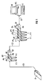
- FIG. 1 shows a basic illustration of a Dental device with a first peripheral device G1, which four storage devices A1 to A4 for there discarded, hose and / or wired instruments I1 to I4 contains.
- G2 is a second peripheral device designated, which two more, in trays A5, A6 contains held instruments I5 and I6.
- the instruments I1 to I4, for example, can be customary for tooth preparation suitable drilling and grinding instruments, while the Instruments I5 and I6 imaging instruments, for example instruments with an integrated video camera or X-ray camera can be.
- the device G1 is via a cable C1 with the serial interface of a personal computer (PC) connected, a keyboard T and a in a known manner Monitor M contains.
- the device G1 contains one later explained electronic component with a logic circuit, with another connection cable C2 another such electronic module in device G2 connected is. Another leads from this Connection cable C3 to a foot switch labeled F.
- All instruments I1 to I6 are sensors in the form of Position detectors P1 to P6 assigned to the removal or Record the storage status of the instruments.
- Position detectors can be light barriers, e.g. in U.S. Patent 4,308,011.
- the position detectors give a corresponding signal to the aforementioned logic circuit, which in turn sends an information signal to the PC passes on, which may then be displayed on the monitor can.
- the foot switch F preferably has several of one Center out in two opposite directions adjustable switching positions.
- the circuitry structure of the PC communicating Instrument storage is based on the block diagram in Fig. 2 explains.
- a logic circuit 100 which is preferably a can be programmed IC, all incoming and outgoing Logic states switched.
- Logic circuit 100 is over a transmit and receive module 101 by means of cable C1 the standard interface of the PC (Fig. 1) connected.
- the Power supply 102 for the circuit takes place preferably via the serial interface from the PC, because this is available by default.
- the logic circuit 100 receives signals from switching elements 103 which are in the instrument trays A1 to A6. in the In the present case, these are position indicators P1 to P6, the storage or removal status of an instrument Report.
- Via the transmit and receive module 101 Signals sent to the PC.
- the logic circuit 101 gives Signals from the PC to display elements 104, which are labeled D1 in FIG and D2 are designated and on the peripheral device G1 or G2 can be present.
- a second peripheral device (G2) is present, it is advantageous to Instrument trays A5 and A6 cascaded one behind the other to connect the interface of the PC.
- the device G2 also contains one corresponding logic circuit, not shown in FIG. 2, as shown in Fig. 2, the cable C2 is connected to the logic circuit 100 in the device G1.
- Another transmission and reception module 105 is likewise provided that performs the same function as that Module 101.
- 106 denotes display elements that also be activated via the logic circuit and the Operational readiness of the instruments, error messages or also display status functions such as speed.
- Designated switching elements that the instruments identify. These switching elements can be in the instrument itself or in the supply hose connected to it be arranged. The outgoing from these switching elements Signals are sent to logic circuit 100 first and then forwarded to the PC via the send module 101.
- This Arrangement has the advantage that only one serial Interface on the PC needs to be occupied.
- the application program in the PC which is assigned to the instrument being pulled, is activated via the logic circuit. If, for example, a drilling instrument with an electric motor drive arranged in the instrument is removed from its storage, the control and / or monitoring program assigned to this instrument is activated in the PC. A neutral state is set when the instrument is put down. If another instrument is then pulled, for example with an integrated video camera (I5 or I6), activated by the logic circuit present in the device G2, the program in the PC is switched to the instrument program assigned to the instrument now being pulled.
- an integrated video camera I5 or I6
- foot switch F which has several switching positions, can, for example, individual in the user program of the PC Instrument programs can be selected and activated.
- the function of the trigger switch on the foot switch by giving the time sequence of triggering a gives additional meaning. For example by simply clicking, double-clicking or holding the Trigger switch extends the function of the foot switch become. If the PC and the serial interface monitoring software not to differentiate from such different switching operations, this will take over the logic circuit in the PC. Depending on the switching sequence and The logic circuit sends the switching time via the serial Interface a coded data word to the PC, which via a known code key from the switching action is informed. Such a data word is usually used seven to eight bits long. This data word can be used by everyone new action to be sent to the PC.
Landscapes
- Health & Medical Sciences (AREA)
- Engineering & Computer Science (AREA)
- General Health & Medical Sciences (AREA)
- Biomedical Technology (AREA)
- Public Health (AREA)
- Epidemiology (AREA)
- Dentistry (AREA)
- Animal Behavior & Ethology (AREA)
- Life Sciences & Earth Sciences (AREA)
- Oral & Maxillofacial Surgery (AREA)
- Veterinary Medicine (AREA)
- Water Supply & Treatment (AREA)
- Business, Economics & Management (AREA)
- General Business, Economics & Management (AREA)
- Medical Informatics (AREA)
- Primary Health Care (AREA)
- Dental Tools And Instruments Or Auxiliary Dental Instruments (AREA)
Applications Claiming Priority (2)
| Application Number | Priority Date | Filing Date | Title |
|---|---|---|---|
| DE4409862A DE4409862C2 (de) | 1994-03-22 | 1994-03-22 | Zahnärztliche Einrichtung mit ein oder mehreren unterschiedlich konfigurierten Instrumenten |
| DE4409862 | 1994-03-22 |
Publications (3)
| Publication Number | Publication Date |
|---|---|
| EP0678280A2 EP0678280A2 (de) | 1995-10-25 |
| EP0678280A3 EP0678280A3 (cg-RX-API-DMAC7.html) | 1995-11-29 |
| EP0678280B1 true EP0678280B1 (de) | 1999-11-17 |
Family
ID=6513511
Family Applications (1)
| Application Number | Title | Priority Date | Filing Date |
|---|---|---|---|
| EP95103432A Expired - Lifetime EP0678280B1 (de) | 1994-03-22 | 1995-03-09 | Zahnärztliche Einrichtung mit ein oder mehreren unterschiedlich konfigurierten Instrumenten |
Country Status (5)
| Country | Link |
|---|---|
| US (1) | US5931669A (cg-RX-API-DMAC7.html) |
| EP (1) | EP0678280B1 (cg-RX-API-DMAC7.html) |
| JP (1) | JPH07265336A (cg-RX-API-DMAC7.html) |
| DE (2) | DE4409862C2 (cg-RX-API-DMAC7.html) |
| DK (1) | DK0678280T3 (cg-RX-API-DMAC7.html) |
Families Citing this family (27)
| Publication number | Priority date | Publication date | Assignee | Title |
|---|---|---|---|---|
| DE19531785A1 (de) * | 1995-08-30 | 1997-03-06 | Loesch Schloms Werner Dipl Ing | Dentalcomputer |
| IT1279733B1 (it) * | 1995-09-28 | 1997-12-16 | Castellini Spa | Sistema di controllo ed assistenza di un riunito dentale |
| DE19601718C2 (de) * | 1996-01-18 | 1999-03-25 | Sirona Dental Systems Gmbh | In der zahnärztlichen Praxis einsetzbares mobiles Gerät zur Aufnahme und Übermittlung von Daten |
| US5921669A (en) * | 1997-03-25 | 1999-07-13 | Schwinn Cycling & Fitness Inc. | Convertible orientation bicycle lamp |
| US6470222B1 (en) * | 1997-08-26 | 2002-10-22 | Rockford Dental Mfg. Co. | Dental delivery system |
| FI109521B (fi) | 1997-11-28 | 2002-08-30 | Planmeca Oy | Kuvausväline, hammashoitokone ja menetelmä kuvausvälineen liittämiseksi hammashoitokoneeseen |
| US6152246A (en) * | 1998-12-02 | 2000-11-28 | Noble Drilling Services, Inc. | Method of and system for monitoring drilling parameters |
| US6798396B2 (en) * | 2000-02-22 | 2004-09-28 | Air Techniques, Inc. | Foot switch interface for operation of computer |
| DE10133593B4 (de) * | 2001-06-12 | 2006-03-23 | Sirona Dental Systems Gmbh | Anordnung und Verfahren zum Betreiben eines mit einem Rechner verbundenen Dentalbehandlungsplatz |
| US7625208B2 (en) | 2002-06-17 | 2009-12-01 | Warner Thomas P | Universal-control mechanism for dental implements |
| US7422432B2 (en) * | 2002-06-17 | 2008-09-09 | Warner Systems, Llc | System and method for remotely controlling devices |
| CN1905851B (zh) * | 2004-01-27 | 2010-11-17 | Xo卡雷公司 | 牙科业务操作系统 |
| FI20041289L (fi) * | 2004-10-05 | 2006-04-06 | Planmeca Oy | Ohjausjärjestely ja menetelmä hammashoitokoneen yhteyteen järjestetyn tietokoneen ohjaamiseksi |
| DE112004003014T5 (de) * | 2004-11-15 | 2008-01-03 | Kabushiki Kaisha Morita Tokyo Seisakusho | Optische Zahndiagnosevorrichtung |
| DE102004060406A1 (de) * | 2004-12-14 | 2006-06-29 | Sirona Dental Systems Gmbh | Zahnärztliche Behandlungseinheit mit Vermessungseinrichtung sowie dreidimensionale Vermessungseinrichtung |
| US20070031781A1 (en) * | 2005-08-02 | 2007-02-08 | Warner Thomas P | System and method for remotely controlling devices |
| US20070030166A1 (en) * | 2005-08-02 | 2007-02-08 | Warner Thomas P | Device selection module and method for selecting devices |
| US7659833B2 (en) * | 2005-08-02 | 2010-02-09 | Warner Thomas P | System and method for remotely controlling devices |
| US7675430B2 (en) * | 2005-08-02 | 2010-03-09 | Warner Thomas P | Device control module and method for controlling devices |
| FI123984B (fi) * | 2007-03-19 | 2014-01-15 | Planmeca Oy | Hammashoitokone, jossa on ohjelmoitavissa olevia toimintoja |
| US8725096B2 (en) | 2010-04-12 | 2014-05-13 | Dentsply International Inc. | Circuit board for controlling wireless dental handpiece |
| US8723668B1 (en) | 2010-11-14 | 2014-05-13 | Gene Michael Strohallen | System and method for controlling at least one device |
| DE102010063234A1 (de) * | 2010-12-16 | 2012-06-21 | Sirona Dental Systems Gmbh | Anordnung zur Durchführung einer Dentalbehandlung und Verfahren zum Betreiben einer solchen Anordnung |
| DE102013207728A1 (de) * | 2013-04-26 | 2014-10-30 | Xion Gmbh | Steuereinheit für eine Mehrzahl von bildaufnehmenden Medizingeräten |
| ES2669418T3 (es) * | 2015-10-29 | 2018-05-25 | Kaltenbach & Voigt Gmbh | Sistema de tratamiento o examen dental y procedimiento de funcionamiento del mismo |
| JP6306642B2 (ja) * | 2016-06-01 | 2018-04-04 | 株式会社吉田製作所 | 歯科用インスツルメントハンガー |
| US10052171B1 (en) | 2017-04-07 | 2018-08-21 | Naif A. Almalki | Intraoral multifunctional dental tool |
Family Cites Families (11)
| Publication number | Priority date | Publication date | Assignee | Title |
|---|---|---|---|---|
| DE2715798C2 (de) * | 1977-04-07 | 1983-09-29 | Kaltenbach & Voigt Gmbh & Co, 7950 Biberach | Zahnärztlicher Behandlungsplatz |
| DE2823858C2 (de) * | 1978-05-31 | 1985-12-19 | Siemens AG, 1000 Berlin und 8000 München | Ablagevorrichtung für zahnärztliche Handstücke |
| DE2844348C2 (de) * | 1978-10-11 | 1985-10-03 | Kaltenbach & Voigt Gmbh & Co, 7950 Biberach | Zahnärztlicher Behandlungsplatz |
| US5016098A (en) * | 1987-03-05 | 1991-05-14 | Fuji Optical Systems, Incorporated | Electronic video dental camera |
| DK159714C (da) * | 1987-12-22 | 1991-04-22 | Den Flex As | Mikroprocessorstyret tandlaegeapparat med et hierakisk ordnet system af betjenings- og justeringsmenuer |
| US4915626A (en) * | 1989-01-18 | 1990-04-10 | Lemmey Edgar S | Dental inspection and display apparatus |
| US5052924A (en) * | 1989-03-22 | 1991-10-01 | Berg Randy J | Fiberoptic imaging dental drill |
| DE4010998A1 (de) * | 1990-04-05 | 1991-10-17 | Diehl Gmbh & Co | Elektronisches geraet zur steuerung von verbrauchern |
| US5257184A (en) * | 1990-04-10 | 1993-10-26 | Mushabac David R | Method and apparatus with multiple data input stylii for collecting curvilinear contour data |
| FR2683665B1 (fr) * | 1991-11-12 | 1993-12-31 | Francis Mouyen | Boitier renfermant l'ensemble des dispositifs informatiques et electroniques, notamment d'imagerie, utilises dans un cabinet dentaire. |
| JPH0824685B2 (ja) * | 1992-11-25 | 1996-03-13 | 株式会社江川 | インプラント構造体の測定方法およびその測定装置 |
-
1994
- 1994-03-22 DE DE4409862A patent/DE4409862C2/de not_active Expired - Fee Related
-
1995
- 1995-03-09 EP EP95103432A patent/EP0678280B1/de not_active Expired - Lifetime
- 1995-03-09 DK DK95103432T patent/DK0678280T3/da active
- 1995-03-09 DE DE59507229T patent/DE59507229D1/de not_active Expired - Lifetime
- 1995-03-22 JP JP7063128A patent/JPH07265336A/ja active Pending
- 1995-03-22 US US08/407,948 patent/US5931669A/en not_active Expired - Lifetime
Also Published As
| Publication number | Publication date |
|---|---|
| DK0678280T3 (da) | 2002-12-23 |
| DE4409862C2 (de) | 1997-06-05 |
| DE59507229D1 (de) | 1999-12-23 |
| JPH07265336A (ja) | 1995-10-17 |
| US5931669A (en) | 1999-08-03 |
| EP0678280A3 (cg-RX-API-DMAC7.html) | 1995-11-29 |
| DE4409862A1 (de) | 1995-09-28 |
| EP0678280A2 (de) | 1995-10-25 |
Similar Documents
| Publication | Publication Date | Title |
|---|---|---|
| EP0678280B1 (de) | Zahnärztliche Einrichtung mit ein oder mehreren unterschiedlich konfigurierten Instrumenten | |
| DE2755782C2 (de) | Steuereinheit für einen Fraktionssammler | |
| EP0894039A1 (de) | Elektrischer rasierapparat oder damit zusammenwirkendes gerät und anordnung zur auswertung von informationen | |
| DE102007003471A1 (de) | Vorrichtung zur Anzeige und Verwaltung von Systemparametern und Daten eines zahnärztlichen Behandlungsplatzes | |
| DE19857613A1 (de) | Intelligente medizinische Behandlungsvorrichtung | |
| EP1090602A1 (de) | Zahnmedizinische Einrichtung | |
| EP1321108A1 (de) | Zahnärztliches Arbeitsgerät | |
| DE19622529A1 (de) | Ansteuereinrichtung | |
| DD261519A5 (de) | Elektronische steuerungsvorrichtung zum steuern von stellgliedern in einer fischbearbeitungsmaschine | |
| DE19607101A1 (de) | Elektronisches Gerät und Einrichtung zur Datenübertragung zwischen zwei gleichartig aufgebauten elektronischen Geräten | |
| DE19644492A1 (de) | Steuergerät zum Anschluß von zahnärztlichen, zahntechnischen oder feinwerktechnischen Behandlungsinstrumenten oder Handstücken | |
| DE3519908A1 (de) | Vorrichtung zur anzeige und ueberwachung eines system-druckes | |
| EP1425904B1 (de) | Körpermontierbares kameratragsystem mit einem multifunktionalen verbund elektrischer komponenten | |
| EP0908803B1 (de) | Rechner für eine Druckmaschine | |
| DE102009033326B4 (de) | Anordnung mit Kommunikationsteilnehmern | |
| DE2323710A1 (de) | Medizinische untersuchungsanlage | |
| DE3308610C2 (cg-RX-API-DMAC7.html) | ||
| EP0207175A1 (de) | Schneidemaschine mit Rechnersteuerung | |
| DE19710480A1 (de) | Unterbrechungsanzeigevorrichtung für ein Halbleiterschaltelement, welches eine Überstrom/Überhitzungs-Schutzfunktion aufweist | |
| DE102007033334A1 (de) | Verfahren zur Erfassung von Biosignalen mittels einer Erfassungseinheit und Vorrichtung hierfür | |
| DE29617827U1 (de) | Steuerungseinrichtung für Solarien | |
| DE19752853C1 (de) | Verfahren und System zum Verarbeiten von Alarmmeldungen in einem Rechnerverbundnetz mit mehreren Personal Computern | |
| DE3942587A1 (de) | Anzeigevorrichtung, insbesondere fuer leitwarten, simulatoren oder dergleichen | |
| DE19635595C2 (de) | Diagnostikeinrichtung mit Mitteln zur digitalen Bildspeicherung | |
| DE102007002906A1 (de) | Mehrkanal-Impulsfolgen-Übertragungsvorrichtung |
Legal Events
| Date | Code | Title | Description |
|---|---|---|---|
| PUAI | Public reference made under article 153(3) epc to a published international application that has entered the european phase |
Free format text: ORIGINAL CODE: 0009012 |
|
| PUAL | Search report despatched |
Free format text: ORIGINAL CODE: 0009013 |
|
| AK | Designated contracting states |
Kind code of ref document: A2 Designated state(s): DE DK FR IT |
|
| AK | Designated contracting states |
Kind code of ref document: A3 Designated state(s): DE DK FR IT |
|
| 17P | Request for examination filed |
Effective date: 19960524 |
|
| RAP1 | Party data changed (applicant data changed or rights of an application transferred) |
Owner name: SIRONA DENTAL SYSTEMS GMBH & CO.KG |
|
| 17Q | First examination report despatched |
Effective date: 19981028 |
|
| GRAG | Despatch of communication of intention to grant |
Free format text: ORIGINAL CODE: EPIDOS AGRA |
|
| GRAG | Despatch of communication of intention to grant |
Free format text: ORIGINAL CODE: EPIDOS AGRA |
|
| GRAH | Despatch of communication of intention to grant a patent |
Free format text: ORIGINAL CODE: EPIDOS IGRA |
|
| RAP1 | Party data changed (applicant data changed or rights of an application transferred) |
Owner name: SIRONA DENTAL SYSTEMS GMBH |
|
| GRAH | Despatch of communication of intention to grant a patent |
Free format text: ORIGINAL CODE: EPIDOS IGRA |
|
| GRAA | (expected) grant |
Free format text: ORIGINAL CODE: 0009210 |
|
| AK | Designated contracting states |
Kind code of ref document: B1 Designated state(s): DE DK FR IT |
|
| ITF | It: translation for a ep patent filed | ||
| REF | Corresponds to: |
Ref document number: 59507229 Country of ref document: DE Date of ref document: 19991223 |
|
| ET | Fr: translation filed | ||
| PLBE | No opposition filed within time limit |
Free format text: ORIGINAL CODE: 0009261 |
|
| STAA | Information on the status of an ep patent application or granted ep patent |
Free format text: STATUS: NO OPPOSITION FILED WITHIN TIME LIMIT |
|
| 26N | No opposition filed | ||
| REG | Reference to a national code |
Ref country code: DK Ref legal event code: T3 |
|
| PGFP | Annual fee paid to national office [announced via postgrant information from national office to epo] |
Ref country code: DK Payment date: 20140323 Year of fee payment: 20 Ref country code: DE Payment date: 20140331 Year of fee payment: 20 |
|
| PGFP | Annual fee paid to national office [announced via postgrant information from national office to epo] |
Ref country code: IT Payment date: 20140325 Year of fee payment: 20 |
|
| PGFP | Annual fee paid to national office [announced via postgrant information from national office to epo] |
Ref country code: FR Payment date: 20140410 Year of fee payment: 20 |
|
| REG | Reference to a national code |
Ref country code: DE Ref legal event code: R071 Ref document number: 59507229 Country of ref document: DE |
|
| REG | Reference to a national code |
Ref country code: DK Ref legal event code: EUP Effective date: 20150309 |