EP0678280B1 - Dental appliance with one or more variously configured instruments - Google Patents
Dental appliance with one or more variously configured instruments Download PDFInfo
- Publication number
- EP0678280B1 EP0678280B1 EP95103432A EP95103432A EP0678280B1 EP 0678280 B1 EP0678280 B1 EP 0678280B1 EP 95103432 A EP95103432 A EP 95103432A EP 95103432 A EP95103432 A EP 95103432A EP 0678280 B1 EP0678280 B1 EP 0678280B1
- Authority
- EP
- European Patent Office
- Prior art keywords
- instruments
- instrument
- logic circuit
- dental appliance
- appliance according
- Prior art date
- Legal status (The legal status is an assumption and is not a legal conclusion. Google has not performed a legal analysis and makes no representation as to the accuracy of the status listed.)
- Expired - Lifetime
Links
Images

Classifications
-
- A—HUMAN NECESSITIES
- A61—MEDICAL OR VETERINARY SCIENCE; HYGIENE
- A61C—DENTISTRY; APPARATUS OR METHODS FOR ORAL OR DENTAL HYGIENE
- A61C1/00—Dental machines for boring or cutting ; General features of dental machines or apparatus, e.g. hand-piece design
- A61C1/0007—Control devices or systems
-
- G—PHYSICS
- G16—INFORMATION AND COMMUNICATION TECHNOLOGY [ICT] SPECIALLY ADAPTED FOR SPECIFIC APPLICATION FIELDS
- G16H—HEALTHCARE INFORMATICS, i.e. INFORMATION AND COMMUNICATION TECHNOLOGY [ICT] SPECIALLY ADAPTED FOR THE HANDLING OR PROCESSING OF MEDICAL OR HEALTHCARE DATA
- G16H40/00—ICT specially adapted for the management or administration of healthcare resources or facilities; ICT specially adapted for the management or operation of medical equipment or devices
- G16H40/60—ICT specially adapted for the management or administration of healthcare resources or facilities; ICT specially adapted for the management or operation of medical equipment or devices for the operation of medical equipment or devices
- G16H40/63—ICT specially adapted for the management or administration of healthcare resources or facilities; ICT specially adapted for the management or operation of medical equipment or devices for the operation of medical equipment or devices for local operation
Definitions
- the invention relates to a dental device according to the preamble of claim 1.
- Such a device is for example from EP-B1-0 391 967 known.
- the known device contains one Number of holders for dynamic, i.e. with drive devices provided instruments, their operating and operating functions show up on a monitoring and control panel to let.
- a microprocessor is available for this purpose is designed to have a number of function display panels on the panel to show on the one hand from instrument-related operating functions and on the other hand by Auxiliary functions can be generated.
- To the microprocessor can also be connected to an alphanumeric keyboard with which it is possible to enter information entered the display fields.
- the surveillance and Control panel can be a screen used to show Text and video information can be used.
- the invention is based on the fact that with such dental institution other than those already mentioned dynamic instruments (drilling or grinding instruments) that primarily serve the preparation, too imaging tools, e.g. Instruments with integrated video camera for intra- or extraoral considerations in the patient's mouth, for use can come.
- the instruments can also be configured differently be. This means, for example, that they are different Attachments (gear, lens attachments or the like) can be provided, or that different in them Media (e.g. with / without light, with / without spray) offered or to be provided.
- Attachments gear, lens attachments or the like
- Media e.g. with / without light, with / without spray
- the specified in claim 1 The invention has for its object a device to improve the genus mentioned in that in addition to the usual preparation instruments, diagnostic imaging Instruments that were previously only available in self-sufficient, peripheral devices were integrated in the same way as the aforementioned preparation instruments, with economical reasonable effort can be operated.
- peripheral devices that work on the special Conditions and requirements such as hygiene, ergonomics, Patient protection, etc., are tailored and used as self-sufficient devices in a dental workplace were arranged by system integration to one Personal computer (PC) through new or different functions can benefit.
- PC Personal computer
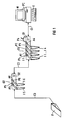
- FIG. 1 shows a basic illustration of a Dental device with a first peripheral device G1, which four storage devices A1 to A4 for there discarded, hose and / or wired instruments I1 to I4 contains.
- G2 is a second peripheral device designated, which two more, in trays A5, A6 contains held instruments I5 and I6.
- the instruments I1 to I4, for example, can be customary for tooth preparation suitable drilling and grinding instruments, while the Instruments I5 and I6 imaging instruments, for example instruments with an integrated video camera or X-ray camera can be.
- the device G1 is via a cable C1 with the serial interface of a personal computer (PC) connected, a keyboard T and a in a known manner Monitor M contains.
- the device G1 contains one later explained electronic component with a logic circuit, with another connection cable C2 another such electronic module in device G2 connected is. Another leads from this Connection cable C3 to a foot switch labeled F.
- All instruments I1 to I6 are sensors in the form of Position detectors P1 to P6 assigned to the removal or Record the storage status of the instruments.
- Position detectors can be light barriers, e.g. in U.S. Patent 4,308,011.
- the position detectors give a corresponding signal to the aforementioned logic circuit, which in turn sends an information signal to the PC passes on, which may then be displayed on the monitor can.
- the foot switch F preferably has several of one Center out in two opposite directions adjustable switching positions.
- the circuitry structure of the PC communicating Instrument storage is based on the block diagram in Fig. 2 explains.
- a logic circuit 100 which is preferably a can be programmed IC, all incoming and outgoing Logic states switched.
- Logic circuit 100 is over a transmit and receive module 101 by means of cable C1 the standard interface of the PC (Fig. 1) connected.
- the Power supply 102 for the circuit takes place preferably via the serial interface from the PC, because this is available by default.
- the logic circuit 100 receives signals from switching elements 103 which are in the instrument trays A1 to A6. in the In the present case, these are position indicators P1 to P6, the storage or removal status of an instrument Report.
- Via the transmit and receive module 101 Signals sent to the PC.
- the logic circuit 101 gives Signals from the PC to display elements 104, which are labeled D1 in FIG and D2 are designated and on the peripheral device G1 or G2 can be present.
- a second peripheral device (G2) is present, it is advantageous to Instrument trays A5 and A6 cascaded one behind the other to connect the interface of the PC.
- the device G2 also contains one corresponding logic circuit, not shown in FIG. 2, as shown in Fig. 2, the cable C2 is connected to the logic circuit 100 in the device G1.
- Another transmission and reception module 105 is likewise provided that performs the same function as that Module 101.
- 106 denotes display elements that also be activated via the logic circuit and the Operational readiness of the instruments, error messages or also display status functions such as speed.
- Designated switching elements that the instruments identify. These switching elements can be in the instrument itself or in the supply hose connected to it be arranged. The outgoing from these switching elements Signals are sent to logic circuit 100 first and then forwarded to the PC via the send module 101.
- This Arrangement has the advantage that only one serial Interface on the PC needs to be occupied.
- the application program in the PC which is assigned to the instrument being pulled, is activated via the logic circuit. If, for example, a drilling instrument with an electric motor drive arranged in the instrument is removed from its storage, the control and / or monitoring program assigned to this instrument is activated in the PC. A neutral state is set when the instrument is put down. If another instrument is then pulled, for example with an integrated video camera (I5 or I6), activated by the logic circuit present in the device G2, the program in the PC is switched to the instrument program assigned to the instrument now being pulled.
- an integrated video camera I5 or I6
- foot switch F which has several switching positions, can, for example, individual in the user program of the PC Instrument programs can be selected and activated.
- the function of the trigger switch on the foot switch by giving the time sequence of triggering a gives additional meaning. For example by simply clicking, double-clicking or holding the Trigger switch extends the function of the foot switch become. If the PC and the serial interface monitoring software not to differentiate from such different switching operations, this will take over the logic circuit in the PC. Depending on the switching sequence and The logic circuit sends the switching time via the serial Interface a coded data word to the PC, which via a known code key from the switching action is informed. Such a data word is usually used seven to eight bits long. This data word can be used by everyone new action to be sent to the PC.
Description
Die Erfindung bezieht sich auf eine zahnärztliche Einrichtung nach dem Oberbegriff des Anspruches 1.The invention relates to a dental device according to the preamble of claim 1.
Eine derartige Einrichtung ist beispielsweise aus EP-B1-0 391 967 bekannt. Die bekannte Einrichtung enthält eine Anzahl Halter für dynamische, d.h. mit Antriebseinrichtungen versehene Instrumente, deren Bedien- und Betriebsfunktionen sich auf einem Überwachungs- und Steuerpaneel aufzeigen lassen. Hierzu ist ein Mikroprozessor vorhanden, der so konzipiert ist, daß auf dem Paneel eine Anzahl von Funktions-Displayfeldern zum visuellen Aufzeigen einerseits von instrumentenbezogenen Bedienfunktionen und andererseits von Hilfsfunktionen generiert werden kann. An den Mikroprozessor kann außerdem eine alphanumerische Tastatur angeschlossen werden, mit der es möglich ist, eingegebene Informationen auf den Displayfeldern aufzuzeigen. Das Überwachungs- und Steuerpaneel kann ein Bildschirm sein, der zum Aufzeigen von Text- und Videoinformationen eingesetzt werden kann.Such a device is for example from EP-B1-0 391 967 known. The known device contains one Number of holders for dynamic, i.e. with drive devices provided instruments, their operating and operating functions show up on a monitoring and control panel to let. A microprocessor is available for this purpose is designed to have a number of function display panels on the panel to show on the one hand from instrument-related operating functions and on the other hand by Auxiliary functions can be generated. To the microprocessor can also be connected to an alphanumeric keyboard with which it is possible to enter information entered the display fields. The surveillance and Control panel can be a screen used to show Text and video information can be used.
Die Erfindung geht davon aus, daß bei einer derartigen zahnärztlichen Einrichtung außer den bereits angesprochenen dynamischen Instrumenten (Bohr- oder Schleifinstrumente), die primär der Präparation dienen, auch bilderfassende Instrumente, z.B. Instrumente mit integrierter Videokamera für intra- oder extraorale Betrachtungen im Patientenmund, zur Anwendung kommen können.The invention is based on the fact that with such dental institution other than those already mentioned dynamic instruments (drilling or grinding instruments) that primarily serve the preparation, too imaging tools, e.g. Instruments with integrated video camera for intra- or extraoral considerations in the patient's mouth, for use can come.
Die Instrumente können außerdem unterschiedlich konfiguriert sein. Dies bedeutet beispielsweise, daß sie mit verschiedenen Aufsätzen (Getriebe-, Objektiv-Aufsätzen oder dergleichen) versehen sein können, oder daß in ihnen unterschiedliche Medien (z.B. mit/ohne Licht, mit/ohne Spray) angeboten bzw. bereit gestellt werden.The instruments can also be configured differently be. This means, for example, that they are different Attachments (gear, lens attachments or the like) can be provided, or that different in them Media (e.g. with / without light, with / without spray) offered or to be provided.
Der im Patentanspruch 1 angegebenen Erfindung liegt die Aufgabe zugrunde, eine Einrichtung der eingangs genannten Gattung dahingehend zu verbessern, daß außer den üblichen Präparations-Instrumenten weitere, zur Diagnose dienende bilderfassende Instrumente, die bisher ausschließlich in autarken, peripheren Geräten eingebunden waren, in gleicher Weise wie die vorgenannten Präparationsinstrumente, mit wirtschaftlich vertretbarem Aufwand betrieben werden können.The specified in claim 1 The invention has for its object a device to improve the genus mentioned in that in addition to the usual preparation instruments, diagnostic imaging Instruments that were previously only available in self-sufficient, peripheral devices were integrated in the same way as the aforementioned preparation instruments, with economical reasonable effort can be operated.
Mit der vorliegenden Erfindung wird eine Möglichkeit aufgezeigt, wie periphere Geräte, die auf die besonderen Bedingungen und Anforderungen wie Hygiene, Ergonomie, Patientenschutz, etc., zugeschnitten sind und die bisher als autarke Geräte an einem zahnärztlichen Arbeitsplatz angeordnet waren, durch Systemeinbindung an einen Personal-Computer (PC) durch neue oder andere Funktionen profitieren können. With the present invention, one possibility demonstrated how peripheral devices that work on the special Conditions and requirements such as hygiene, ergonomics, Patient protection, etc., are tailored and used as self-sufficient devices in a dental workplace were arranged by system integration to one Personal computer (PC) through new or different functions can benefit.
Gemäß einer vorteilhaften Ausgestaltung der Erfindung, bei der die Einrichtung den Instrumenten zugeordnete Ablagehalterungen sowie diesen zugeordnete Positionsmeldesensoren enthält, wie sie beispielsweise aus der US-PS 4 308 011 bekannt sind, können Mittel vorhanden sein, die den Betriebszustand eines instrumentenbezogenen Antriebes, Abweichungen von Soll-Betriebszuständen oder andere Fehlermeldungen dem PC melden und ggf. am Monitor anzeigen. So kann beispielsweise die Entnahme einer IntraoralVideokamera dem PC angezeigt werden, welcher wiederum selbständig das entsprechende Programm aktiviert. Über Bedien- bzw. Schaltelemente an der Kamera oder auch an einem Fußschalter kann der Benutzer sich durch das Programm bewegen und entsprechende Funktionen auslösen. Sobald das Instrument wieder in seine Ablage zurückgelegt wird, wird der ursprüngliche Zustand wieder hergestellt. Wie bereits angesprochen, können periphere Informationen, insbesondere auch Fehlermeldungen, über den Logik-Schaltkreis mitgeteilt und am PC-Monitor angezeigt werden.According to an advantageous embodiment of the Invention in which the establishment of the instruments associated storage brackets and associated with them Contains position detection sensors, such as those from U.S. Patent 4,308,011 are known there may be means available to the Operating state of an instrument-related drive, Deviations from target operating states or others Report error messages to the PC and display them on the monitor if necessary. For example, the removal of an intraoral video camera be displayed on the PC, which in turn automatically activated the corresponding program. over Operating or switching elements on the camera or on one The foot switch allows the user to move through the program and trigger corresponding functions. Once the instrument put back in its storage, the original condition restored. As before peripheral information, in particular also error messages communicated via the logic circuit and displayed on the PC monitor.
Obgleich an sich jede übliche Schnittstelle (ISA-Bus für Einsteckkarten, parallele oder serielle Schnittstelle, Multifunktionsschnittstelle) genutzt werden kann, ist es vorteilhaft, die serielle Schnittstelle für die Datenübertragung heranzuziehen.Although in itself every common interface (ISA bus for Plug-in cards, parallel or serial interface, Multifunction interface), it is advantageous, the serial interface for the Data transmission.
Weitere vorteilhafte Ausgestaltungen und Weiterbildungen der Erfindung ergeben sich aus den Patentansprüchen sowie dem nachfolgend anhand der Zeichnung näher erläuterten Ausführungsbeispiel. Es zeigen:
- Fig. 1
- eine Prinzipdarstellung einer zahnärztlichen Einrichtung gemäß der Erfindung, und
- Fig. 2
- ein Blockschaltbild vom Logik-Schaltkreis.
- Fig. 1
- a schematic diagram of a dental device according to the invention, and
- Fig. 2
- a block diagram of the logic circuit.
Die Fig. 1 zeigt in einer Prinzipdarstellung eine zahnärztliche Einrichtung mit einem ersten peripheren Gerät G1, welches vier Ablagevorrichtungen A1 bis A4 für dort abgelegte, schlauch- und/oder kabelgebundene Instrumente I1 bis I4 enthält. Mit G2 ist ein zweites peripheres Gerät bezeichnet, welches zwei weitere, in Ablagen A5, A6 gehalterte Instrumente I5 und I6 enthält. Die Instrumente I1 bis I4 können beispielsweise übliche, zur Zahnpräparation geeignete Bohr- und Schleifinstrumente sein, während die Instrumente I5 und I6 bilderfassende Instrumente, beispielsweise Instrumente mit integrierter Videokamera oder Röntgenkamera sein können. Das Gerät G1 ist über ein Kabel C1 mit der seriellen Schnittstelle eines Personalcomputers (PC) verbunden, der in bekannter Weise eine Tastatur T sowie einen Monitor M enthält. Das Gerät G1 enthält einen später noch näher erläuterten Elektronikbaustein mit einem Logik-Schaltkreis, der über ein weiteres Verbindungskabel C2 mit einem weiteren solchen Elektronikbaustein im Gerät G2 verbunden ist. Von diesem führt wiederum ein weiteres Verbindungskabel C3 zu einem mit F bezeichneten Fußschalter.1 shows a basic illustration of a Dental device with a first peripheral device G1, which four storage devices A1 to A4 for there discarded, hose and / or wired instruments I1 to I4 contains. With G2 is a second peripheral device designated, which two more, in trays A5, A6 contains held instruments I5 and I6. The instruments I1 to I4, for example, can be customary for tooth preparation suitable drilling and grinding instruments, while the Instruments I5 and I6 imaging instruments, for example instruments with an integrated video camera or X-ray camera can be. The device G1 is via a cable C1 with the serial interface of a personal computer (PC) connected, a keyboard T and a in a known manner Monitor M contains. The device G1 contains one later explained electronic component with a logic circuit, with another connection cable C2 another such electronic module in device G2 connected is. Another leads from this Connection cable C3 to a foot switch labeled F.
Sämtlichen Instrumenten I1 bis I6 sind Sensoren in Form von Positionsmeldern P1 bis P6 zugeordnet, welche den Entnahme- bzw. Ablagezustand der Instrumente erfassen. Solche Positionsmelder können Lichtschranken sein, wie sie z.B. in der US-PS 4 308 011 beschrieben sind. Die Positionsmelder geben ein entsprechendes Signal an den vorerwähnten Logik-Schaltkreis, der wiederum ein Informationssignal an den PC weitergibt, welches dann ggf. am Monitor angezeigt werden kann. All instruments I1 to I6 are sensors in the form of Position detectors P1 to P6 assigned to the removal or Record the storage status of the instruments. Such Position detectors can be light barriers, e.g. in U.S. Patent 4,308,011. The position detectors give a corresponding signal to the aforementioned logic circuit, which in turn sends an information signal to the PC passes on, which may then be displayed on the monitor can.
Der Fußschalter F besitzt vorzugsweise mehrere aus einer Mittelstellung heraus in zwei entgegengesetze Richtungen verstellbare Schaltpositionen.The foot switch F preferably has several of one Center out in two opposite directions adjustable switching positions.
Der schaltungstechnische Aufbau der PC-kommunizierenden Instrumentenablage wird anhand des Blockschaltbildes in Fig. 2 erläutert.The circuitry structure of the PC communicating Instrument storage is based on the block diagram in Fig. 2 explains.
Über einen Logik-Schaltkreis 100, der vorzugsweise ein
programmierter IC sein kann, werden alle ein- und ausgehenden
Logikzustände geschaltet. Der Logik-Schaltkreis 100 ist über
einen Sende- und Empfangsbaustein 101 mittels Kabel C1 mit
der Standardschnittstelle des PC's (Fig. 1) verbunden. Die
Spannungsversorgung 102 für den Schaltkreis erfolgt
vorzugsweise über die serielle Schnittstelle vom PC aus, da
diese standardmäßig zur Verfügung steht. Der Logik-Schaltkreis
100 erhält Signale von Schaltelementen 103, die
sich in den Instrumentenablagen A1 bis A6 befinden. Im
vorliegenden Fall sind dies die Positionsmelder P1 bis P6,
die den Ablage- bzw. Entnahmezustand eines Instruments
melden. Über den Sende- und Empfangsbaustein 101 werden die
Signale zum PC gesendet. Der Logik-Schaltkreis 101 gibt
Signale vom PC an Anzeigeelemente 104, die in Fig. 1 mit D1
und D2 bezeichnet sind und am peripheren Gerät G1 oder G2
vorhanden sein können.Via a
Wenn, wie im Ausführungsbeispiel dargestellt, ein zweites
peripheres Gerät (G2) vorhanden ist, ist es vorteilhaft, die
Instrumentenablagen A5 und A6 hintereinander kaskadiert an
die Schnittstelle des PC's anzuschließen. Im aufgezeigten
Anwendungsfall enthält dann auch das Gerät G2 einen
entsprechenden, in Fig. 2 nicht dargestellten Logik-Schaltkreis,
wie in Fig. 2 dargestellt, der über das Kabel C2
mit dem Logik-Schaltkreis 100 im Gerät G1 verbunden ist.
Ebenso ist ein weiterer Sende- und Empfangsbaustein 105
vorgesehen, der die gleiche Funktion erfüllt, wie der
Baustein 101. Mit 106 sind Anzeigeelemente bezeichnet, die
ebenfalls über den Logikschaltkreis aktiviert werden und die
Betriebsbereitschaft der Instrumente, Fehlermeldungen oder
auch Statusfunktionen, wie Drehzahl, anzeigen. Mit 107 sind
Schaltelemente bezeichnet, die die Instrumente
identifizieren. Diese Schaltelemente können im Instrument
selbst oder auch im daran angeschlossenen Versorgungsschlauch
angeordnet sein. Die von diesen Schaltelementen ausgehenden
Signale werden zunächst an den Logik-Schaltkreis 100 und dann
über den Sende-Baustein 101 an denn PC weitergeleitet. Diese
Anordnung hat den Vorteil, daß nur eine serielle
Schnittstelle am PC belegt zu werden braucht.If, as shown in the embodiment, a second
peripheral device (G2) is present, it is advantageous to
Instrument trays A5 and A6 cascaded one behind the other
to connect the interface of the PC. In the shown
In this case, the device G2 also contains one
corresponding logic circuit, not shown in FIG. 2,
as shown in Fig. 2, the cable C2
is connected to the
Nachfolgend werden einige besonders vorteilhafte Anwendungen
geschildert:
Bei Entnahme eines Instrumentes I1 bis I4 aus seiner
Halterung A1 bis A4 wird über den Logik-Schaltkreis das
Anwendungsprogramm im PC, das jeweils dem gezogenen
Instrument zugeordnet ist, aktiviert. Wird beispielsweise ein
Bohrinstrument mit einem im Instrument angeordneten
Elektromotorantrieb aus seiner Ablage entnommen, so wird das
diesem Instrument zugeordnete Steuer- und/oder
Überwachungsprogramm im PC aktiviert. Bei Ablage des
Instrumentes wird ein neutraler Zustand eingestellt. Wird
danach ein anderes Instrument, beispielsweise mit
integrierter Videokamera (I5 oder I6), gezogen, so wird,
aktiviert durch den im Gerät G2 vorhandenen Logik-Schaltkreis,
im PC das Programm auf das dem jetzt gezogenen
Instrument zugeordnete Instrumentenprogramm umgeschaltet.Some particularly advantageous applications are described below:
When an instrument I1 to I4 is removed from its holder A1 to A4, the application program in the PC, which is assigned to the instrument being pulled, is activated via the logic circuit. If, for example, a drilling instrument with an electric motor drive arranged in the instrument is removed from its storage, the control and / or monitoring program assigned to this instrument is activated in the PC. A neutral state is set when the instrument is put down. If another instrument is then pulled, for example with an integrated video camera (I5 or I6), activated by the logic circuit present in the device G2, the program in the PC is switched to the instrument program assigned to the instrument now being pulled.
Unter Bezugnahme auf das abgespeicherte Programm kann in dem erwähnten Fall beispielsweise ein am Instrument oder auch am Fußschalter F vorhandener Auslöseschalter ein bestimmtes Videobild "einfrieren". With reference to the stored program in the mentioned case, for example, on the instrument or on Foot switch F existing trigger switch a certain one "Freeze" video image.
Mit dem Fußschalter F, der mehrere Schaltpositionen aufweist, können beispielsweise im Anwenderprogramm des PC's einzelne Instrumentenprogramme ausgewählt und aktiviert werden.With the foot switch F, which has several switching positions, can, for example, individual in the user program of the PC Instrument programs can be selected and activated.
Im Rahmen der Erfindung ist es möglich, die vorhandene Funktion des Auslöseschalters am Fußschalter zu erweitern, indem man der zeitlichen Abfolge des Auslösens eine zusätzliche Bedeutung zukommen läßt. So kann beispielsweise durch einfaches Klicken, Doppelklicken oder Halten des Auslöseschalters die Funktion des Fußschalters erweitert werden. Falls der PC und die die serielle Schnittstelle überwachende Software nicht zur Differenzierung von solchen unterschiedlichen Schaltvorgängen ausgelegt ist, wird dies die Logik-Schaltung im PC übernehmen. Je nach Schaltfolge und Schaltdauer sendet die Logik-Schaltung über die serielle Schnittstelle ein codiertes Datenwort an den PC, welcher über einen an sich bekannten Codeschlüssel von der Schaltaktion informiert wird. Üblicherweise ist ein solches Datenwort sieben bis acht Bit lang. Dieses Datenwort kann bei jeder neuen Aktion zum PC gesendet werden.Within the scope of the invention it is possible to use the existing one Extend the function of the trigger switch on the foot switch, by giving the time sequence of triggering a gives additional meaning. For example by simply clicking, double-clicking or holding the Trigger switch extends the function of the foot switch become. If the PC and the serial interface monitoring software not to differentiate from such different switching operations, this will take over the logic circuit in the PC. Depending on the switching sequence and The logic circuit sends the switching time via the serial Interface a coded data word to the PC, which via a known code key from the switching action is informed. Such a data word is usually used seven to eight bits long. This data word can be used by everyone new action to be sent to the PC.
Claims (8)
- Dental appliance, containing one or more variously configured preparation instruments (I1 to I4) which are retained in depositing devices (A1 to A4) and are assigned sensors (P1 to P4), which detect the configuration and/depositing state of the preparation instruments, and a control apparatus assigned to the preparation instruments and comprising a microprocessor, a keyboard and a screen, with the aid of which instrument-related functions can be displayed on the screen, and if appropriate activated with the aid of a foot switch (F), in dependence on removal or depositing of an instrument, characterized in that the preparation instruments (I1 to I4) and further, image-acquiring instruments (I5, I6), which are used for diagnosis, share a personal computer (PC) with keyboard (T) and screen (M) which contains the microprocessor and has a plurality of interfaces, via one interface of which data from instrument-related functions can be read in and out, a plurality of application programs assigned to the various instruments being installed in the personal computer (PC), and in that a logic circuit (100) is present, which is connected to the one interface of the PC, on the one hand, and to switching and display elements (103, 104, 106, 107), on the other hand, bidirectional operating data corresponding to the instruments or sensors assigned to the instruments being transferred via the logic circuit (100) and the interface of the PC, and the logic circuit (100), in dependence on an instrument removed from a depositing device (A1 to A4), activating the personal computer (PC) in respect of providing the application program assigned to the instrument removed.
- Dental appliance according to Claim 1, characterized in that means are present which display the operating state of an instrument-related drive on the screen (M).
- Dental appliance according to Claim 2, characterized in that the application program of an instrument is designed in such a way that deviations from desired operating values of the drive are displayed on the screen (M).
- Dental appliance according to one of Claims 1 to 3, characterized in that a foot switch (F) is provided, which has a plurality of switching positions which enable the application programs, preferably instrument-related application programs, to be selected via the logic circuit (100).
- Dental appliance according to one of Claims 1 to 4, characterized in that the logic circuit (100) is connected to a serial interface of the PC.
- Dental appliance according to one of Claims 1 to 5, characterized in that one or more instruments (I5, I6) are connected to the interface of the PC such that they are cascaded in series.
- Dental appliance according to Claim 6, characterized in that a plurality of instruments are combined into groups (I1 to I4; I5, I6), each group being assigned a logic circuit.
- Dental appliance according to one of Claims 1 to 7, characterized in that the logic circuit is designed in such a way that it identifies the type of temporal activation of the switching elements and converts it into a PC-identifiable code and transfers it, the information being transferred bidirectionally in coded form.
Applications Claiming Priority (2)
| Application Number | Priority Date | Filing Date | Title |
|---|---|---|---|
| DE4409862A DE4409862C2 (en) | 1994-03-22 | 1994-03-22 | Dental facility with one or more differently configured instruments |
| DE4409862 | 1994-03-22 |
Publications (3)
| Publication Number | Publication Date |
|---|---|
| EP0678280A2 EP0678280A2 (en) | 1995-10-25 |
| EP0678280A3 EP0678280A3 (en) | 1995-11-29 |
| EP0678280B1 true EP0678280B1 (en) | 1999-11-17 |
Family
ID=6513511
Family Applications (1)
| Application Number | Title | Priority Date | Filing Date |
|---|---|---|---|
| EP95103432A Expired - Lifetime EP0678280B1 (en) | 1994-03-22 | 1995-03-09 | Dental appliance with one or more variously configured instruments |
Country Status (5)
| Country | Link |
|---|---|
| US (1) | US5931669A (en) |
| EP (1) | EP0678280B1 (en) |
| JP (1) | JPH07265336A (en) |
| DE (2) | DE4409862C2 (en) |
| DK (1) | DK0678280T3 (en) |
Families Citing this family (27)
| Publication number | Priority date | Publication date | Assignee | Title |
|---|---|---|---|---|
| DE19531785A1 (en) * | 1995-08-30 | 1997-03-06 | Loesch Schloms Werner Dipl Ing | Computer system for dentists |
| IT1279733B1 (en) * | 1995-09-28 | 1997-12-16 | Castellini Spa | CONTROL AND ASSISTANCE SYSTEM OF A DENTAL UNIT |
| DE19601718C2 (en) * | 1996-01-18 | 1999-03-25 | Sirona Dental Systems Gmbh | Mobile device that can be used in dental practice to record and transmit data |
| US5921669A (en) * | 1997-03-25 | 1999-07-13 | Schwinn Cycling & Fitness Inc. | Convertible orientation bicycle lamp |
| US6470222B1 (en) * | 1997-08-26 | 2002-10-22 | Rockford Dental Mfg. Co. | Dental delivery system |
| FI109521B (en) | 1997-11-28 | 2002-08-30 | Planmeca Oy | An imaging device, a dental apparatus, and a method for attaching an imaging apparatus to a dental apparatus |
| US6152246A (en) * | 1998-12-02 | 2000-11-28 | Noble Drilling Services, Inc. | Method of and system for monitoring drilling parameters |
| US6798396B2 (en) * | 2000-02-22 | 2004-09-28 | Air Techniques, Inc. | Foot switch interface for operation of computer |
| DE10133593B4 (en) * | 2001-06-12 | 2006-03-23 | Sirona Dental Systems Gmbh | Arrangement and method for operating a dental treatment station connected to a computer |
| US7625208B2 (en) | 2002-06-17 | 2009-12-01 | Warner Thomas P | Universal-control mechanism for dental implements |
| US7422432B2 (en) * | 2002-06-17 | 2008-09-09 | Warner Systems, Llc | System and method for remotely controlling devices |
| DK1725206T3 (en) * | 2004-01-27 | 2011-10-31 | Xo Care As | Operating system for dental practice |
| FI20041289A (en) * | 2004-10-05 | 2006-04-06 | Planmeca Oy | Control Arrangement and Method for Controlling a Computer Connected to a Dental Machine |
| DE112004003014T5 (en) * | 2004-11-15 | 2008-01-03 | Kabushiki Kaisha Morita Tokyo Seisakusho | Optical dental diagnostic device |
| DE102004060406A1 (en) * | 2004-12-14 | 2006-06-29 | Sirona Dental Systems Gmbh | Dental treatment unit with measuring device and three-dimensional measuring device |
| US7675430B2 (en) * | 2005-08-02 | 2010-03-09 | Warner Thomas P | Device control module and method for controlling devices |
| US7659833B2 (en) * | 2005-08-02 | 2010-02-09 | Warner Thomas P | System and method for remotely controlling devices |
| US20070030166A1 (en) * | 2005-08-02 | 2007-02-08 | Warner Thomas P | Device selection module and method for selecting devices |
| US20070031781A1 (en) * | 2005-08-02 | 2007-02-08 | Warner Thomas P | System and method for remotely controlling devices |
| FI123984B (en) * | 2007-03-19 | 2014-01-15 | Planmeca Oy | Dental unit with programmable functions |
| WO2011130236A1 (en) | 2010-04-12 | 2011-10-20 | Levin, Leana | System including a wireless dental instrument and universal wireless foot controller |
| US8723668B1 (en) | 2010-11-14 | 2014-05-13 | Gene Michael Strohallen | System and method for controlling at least one device |
| DE102010063234A1 (en) * | 2010-12-16 | 2012-06-21 | Sirona Dental Systems Gmbh | Arrangement for carrying out a dental treatment and method for operating such an arrangement |
| DE102013207728A1 (en) * | 2013-04-26 | 2014-10-30 | Xion Gmbh | Control unit for a plurality of image-receiving medical devices |
| ES2669418T3 (en) | 2015-10-29 | 2018-05-25 | Kaltenbach & Voigt Gmbh | Dental treatment or examination system and its operating procedure |
| JP6306642B2 (en) * | 2016-06-01 | 2018-04-04 | 株式会社吉田製作所 | Dental instrument hanger |
| US10052171B1 (en) | 2017-04-07 | 2018-08-21 | Naif A. Almalki | Intraoral multifunctional dental tool |
Family Cites Families (11)
| Publication number | Priority date | Publication date | Assignee | Title |
|---|---|---|---|---|
| DE2715798C2 (en) * | 1977-04-07 | 1983-09-29 | Kaltenbach & Voigt Gmbh & Co, 7950 Biberach | Dental treatment place |
| DE2823858C2 (en) * | 1978-05-31 | 1985-12-19 | Siemens AG, 1000 Berlin und 8000 München | Storage device for dental handpieces |
| DE2844348C2 (en) * | 1978-10-11 | 1985-10-03 | Kaltenbach & Voigt Gmbh & Co, 7950 Biberach | Dental treatment place |
| US5016098A (en) * | 1987-03-05 | 1991-05-14 | Fuji Optical Systems, Incorporated | Electronic video dental camera |
| DK159714C (en) * | 1987-12-22 | 1991-04-22 | Den Flex As | MICROPROCESSOR-CONTROLLED DENTAL APPLIANCE WITH A HIERARCHIC ORGANIZED SYSTEM OF OPERATION AND ADJUSTMENT MENU |
| US4915626A (en) * | 1989-01-18 | 1990-04-10 | Lemmey Edgar S | Dental inspection and display apparatus |
| US5052924A (en) * | 1989-03-22 | 1991-10-01 | Berg Randy J | Fiberoptic imaging dental drill |
| DE4010998A1 (en) * | 1990-04-05 | 1991-10-17 | Diehl Gmbh & Co | Electronic control for household appliance - uses digital display to set time, temp. etc. for oven, washer, dryer, etc. |
| US5257184A (en) * | 1990-04-10 | 1993-10-26 | Mushabac David R | Method and apparatus with multiple data input stylii for collecting curvilinear contour data |
| FR2683665B1 (en) * | 1991-11-12 | 1993-12-31 | Francis Mouyen | HOUSING CONTAINING ALL COMPUTER AND ELECTRONIC DEVICES, ESPECIALLY IMAGING, USED IN A DENTAL CABINET. |
| JPH0824685B2 (en) * | 1992-11-25 | 1996-03-13 | 株式会社江川 | Implant structure measuring method and measuring apparatus |
-
1994
- 1994-03-22 DE DE4409862A patent/DE4409862C2/en not_active Expired - Fee Related
-
1995
- 1995-03-09 DE DE59507229T patent/DE59507229D1/en not_active Expired - Lifetime
- 1995-03-09 EP EP95103432A patent/EP0678280B1/en not_active Expired - Lifetime
- 1995-03-09 DK DK95103432T patent/DK0678280T3/en active
- 1995-03-22 JP JP7063128A patent/JPH07265336A/en active Pending
- 1995-03-22 US US08/407,948 patent/US5931669A/en not_active Expired - Lifetime
Also Published As
| Publication number | Publication date |
|---|---|
| DE59507229D1 (en) | 1999-12-23 |
| DK0678280T3 (en) | 2002-12-23 |
| DE4409862C2 (en) | 1997-06-05 |
| EP0678280A2 (en) | 1995-10-25 |
| US5931669A (en) | 1999-08-03 |
| DE4409862A1 (en) | 1995-09-28 |
| EP0678280A3 (en) | 1995-11-29 |
| JPH07265336A (en) | 1995-10-17 |
Similar Documents
| Publication | Publication Date | Title |
|---|---|---|
| EP0678280B1 (en) | Dental appliance with one or more variously configured instruments | |
| DE3414518A1 (en) | CONTROL PANEL FOR A COMPUTER-BASED X-RAY TOMOGRAPH | |
| WO1996037163A1 (en) | Process and device for the computer-assisted restoration of teeth | |
| DE2755782C2 (en) | Control unit for a fraction collector | |
| DE102007003471A1 (en) | Device for displaying and managing system parameters and data from a dental treatment center | |
| EP1151821A2 (en) | Screw-driving system | |
| DE19857613A1 (en) | Intelligent medical treatment device | |
| DE19948620A1 (en) | Dental facility | |
| DE19622529A1 (en) | Control device | |
| DE4314484B4 (en) | Data acquisition approach to a mobile electronic multimeter, in particular a handheld multimeter | |
| EP0623878A2 (en) | Display device for installation bus system | |
| EP1321108A1 (en) | Dental apparatus | |
| DD261519A5 (en) | ELECTRONIC CONTROL DEVICE FOR CONTROLLING ADJUSTMENTS IN A FISH PROCESSING MACHINE | |
| DE19607101A1 (en) | Electronic device and device for data transmission between two identical electronic devices | |
| DE19644492A1 (en) | Control unit for connecting dental, dental technology or precision engineering treatment instruments or handpieces | |
| EP0723686B1 (en) | Digital integration system for integrating diagnostic imaging and data-processing devices into edp systems | |
| DE3519908A1 (en) | Device for displaying and monitoring a system pressure | |
| EP0486717A1 (en) | Medical diagnostic system | |
| DE3220645A1 (en) | DEVICE AND METHOD FOR MONITORING THE OPERATION OF AN ENGINE CONTROL COMPUTER | |
| EP1196829B1 (en) | Module for controlling a drive | |
| DE4415818C2 (en) | Arrangement for the digital integration of diagnostic imaging and data processing equipment in EDP systems | |
| EP0207175A1 (en) | Cutting machine with computer control | |
| EP2161920A2 (en) | Camera support device worn on the body comprising a multifunctional assembly of electrical components | |
| DE3500440A1 (en) | DEVICE FOR ELECTRONIC ERROR DISPLAY, IN PARTICULAR MOTOR ELECTRONICS IN MOTOR VEHICLES | |
| DE19710480A1 (en) | Cut-off display mechanism for semiconductor switching element |
Legal Events
| Date | Code | Title | Description |
|---|---|---|---|
| PUAI | Public reference made under article 153(3) epc to a published international application that has entered the european phase |
Free format text: ORIGINAL CODE: 0009012 |
|
| PUAL | Search report despatched |
Free format text: ORIGINAL CODE: 0009013 |
|
| AK | Designated contracting states |
Kind code of ref document: A2 Designated state(s): DE DK FR IT |
|
| AK | Designated contracting states |
Kind code of ref document: A3 Designated state(s): DE DK FR IT |
|
| 17P | Request for examination filed |
Effective date: 19960524 |
|
| RAP1 | Party data changed (applicant data changed or rights of an application transferred) |
Owner name: SIRONA DENTAL SYSTEMS GMBH & CO.KG |
|
| 17Q | First examination report despatched |
Effective date: 19981028 |
|
| GRAG | Despatch of communication of intention to grant |
Free format text: ORIGINAL CODE: EPIDOS AGRA |
|
| GRAG | Despatch of communication of intention to grant |
Free format text: ORIGINAL CODE: EPIDOS AGRA |
|
| GRAH | Despatch of communication of intention to grant a patent |
Free format text: ORIGINAL CODE: EPIDOS IGRA |
|
| RAP1 | Party data changed (applicant data changed or rights of an application transferred) |
Owner name: SIRONA DENTAL SYSTEMS GMBH |
|
| GRAH | Despatch of communication of intention to grant a patent |
Free format text: ORIGINAL CODE: EPIDOS IGRA |
|
| GRAA | (expected) grant |
Free format text: ORIGINAL CODE: 0009210 |
|
| AK | Designated contracting states |
Kind code of ref document: B1 Designated state(s): DE DK FR IT |
|
| ITF | It: translation for a ep patent filed |
Owner name: DE DOMINICIS & MAYER S.R.L. |
|
| REF | Corresponds to: |
Ref document number: 59507229 Country of ref document: DE Date of ref document: 19991223 |
|
| ET | Fr: translation filed | ||
| PLBE | No opposition filed within time limit |
Free format text: ORIGINAL CODE: 0009261 |
|
| STAA | Information on the status of an ep patent application or granted ep patent |
Free format text: STATUS: NO OPPOSITION FILED WITHIN TIME LIMIT |
|
| 26N | No opposition filed | ||
| REG | Reference to a national code |
Ref country code: DK Ref legal event code: T3 |
|
| PGFP | Annual fee paid to national office [announced via postgrant information from national office to epo] |
Ref country code: DK Payment date: 20140323 Year of fee payment: 20 Ref country code: DE Payment date: 20140331 Year of fee payment: 20 |
|
| PGFP | Annual fee paid to national office [announced via postgrant information from national office to epo] |
Ref country code: IT Payment date: 20140325 Year of fee payment: 20 |
|
| PGFP | Annual fee paid to national office [announced via postgrant information from national office to epo] |
Ref country code: FR Payment date: 20140410 Year of fee payment: 20 |
|
| REG | Reference to a national code |
Ref country code: DE Ref legal event code: R071 Ref document number: 59507229 Country of ref document: DE |
|
| REG | Reference to a national code |
Ref country code: DK Ref legal event code: EUP Effective date: 20150309 |