EP0677733B1 - Gaslaser und Gasnachweis damit - Google Patents
Gaslaser und Gasnachweis damit Download PDFInfo
- Publication number
- EP0677733B1 EP0677733B1 EP95100163A EP95100163A EP0677733B1 EP 0677733 B1 EP0677733 B1 EP 0677733B1 EP 95100163 A EP95100163 A EP 95100163A EP 95100163 A EP95100163 A EP 95100163A EP 0677733 B1 EP0677733 B1 EP 0677733B1
- Authority
- EP
- European Patent Office
- Prior art keywords
- lambda
- laser
- gas
- arrangement according
- detector
- Prior art date
- Legal status (The legal status is an assumption and is not a legal conclusion. Google has not performed a legal analysis and makes no representation as to the accuracy of the status listed.)
- Expired - Lifetime
Links
- 238000001514 detection method Methods 0.000 title claims description 18
- 239000007789 gas Substances 0.000 claims description 29
- 238000005259 measurement Methods 0.000 claims description 20
- QGZKDVFQNNGYKY-UHFFFAOYSA-N Ammonia Chemical compound N QGZKDVFQNNGYKY-UHFFFAOYSA-N 0.000 claims description 19
- 230000010354 integration Effects 0.000 claims description 12
- UGFAIRIUMAVXCW-UHFFFAOYSA-N Carbon monoxide Chemical compound [O+]#[C-] UGFAIRIUMAVXCW-UHFFFAOYSA-N 0.000 claims description 11
- 239000003546 flue gas Substances 0.000 claims description 11
- 238000011156 evaluation Methods 0.000 claims description 8
- 229910021529 ammonia Inorganic materials 0.000 claims description 7
- 230000008878 coupling Effects 0.000 claims description 7
- 238000010168 coupling process Methods 0.000 claims description 7
- 238000005859 coupling reaction Methods 0.000 claims description 7
- 239000000779 smoke Substances 0.000 claims description 7
- 230000003287 optical effect Effects 0.000 claims description 6
- 230000007704 transition Effects 0.000 claims description 6
- 238000010521 absorption reaction Methods 0.000 claims description 5
- 238000006073 displacement reaction Methods 0.000 claims description 5
- 239000000203 mixture Substances 0.000 claims description 4
- 230000031700 light absorption Effects 0.000 claims description 3
- 239000000463 material Substances 0.000 claims 8
- 229910000069 nitrogen hydride Inorganic materials 0.000 claims 3
- 230000006978 adaptation Effects 0.000 claims 1
- 239000000126 substance Substances 0.000 description 9
- 238000013461 design Methods 0.000 description 5
- 230000003321 amplification Effects 0.000 description 4
- 230000008901 benefit Effects 0.000 description 4
- 238000003199 nucleic acid amplification method Methods 0.000 description 4
- 230000005540 biological transmission Effects 0.000 description 3
- 230000005855 radiation Effects 0.000 description 3
- CURLTUGMZLYLDI-UHFFFAOYSA-N Carbon dioxide Chemical compound O=C=O CURLTUGMZLYLDI-UHFFFAOYSA-N 0.000 description 2
- 239000000919 ceramic Substances 0.000 description 2
- 230000008859 change Effects 0.000 description 2
- 238000010276 construction Methods 0.000 description 2
- 238000010586 diagram Methods 0.000 description 2
- 230000000694 effects Effects 0.000 description 2
- 238000000295 emission spectrum Methods 0.000 description 2
- VNWKTOKETHGBQD-UHFFFAOYSA-N methane Natural products C VNWKTOKETHGBQD-UHFFFAOYSA-N 0.000 description 2
- 230000004044 response Effects 0.000 description 2
- 230000001360 synchronised effect Effects 0.000 description 2
- 108010076504 Protein Sorting Signals Proteins 0.000 description 1
- WUCKNWYBLRBMPA-UHFFFAOYSA-N [Hg].[Hg].[Cd] Chemical compound [Hg].[Hg].[Cd] WUCKNWYBLRBMPA-UHFFFAOYSA-N 0.000 description 1
- 230000008033 biological extinction Effects 0.000 description 1
- 229910002092 carbon dioxide Inorganic materials 0.000 description 1
- 239000001569 carbon dioxide Substances 0.000 description 1
- 238000002485 combustion reaction Methods 0.000 description 1
- 238000001816 cooling Methods 0.000 description 1
- 238000013016 damping Methods 0.000 description 1
- 238000000354 decomposition reaction Methods 0.000 description 1
- 239000000428 dust Substances 0.000 description 1
- 230000005284 excitation Effects 0.000 description 1
- 230000002349 favourable effect Effects 0.000 description 1
- 230000007274 generation of a signal involved in cell-cell signaling Effects 0.000 description 1
- PCHJSUWPFVWCPO-UHFFFAOYSA-N gold Chemical compound [Au] PCHJSUWPFVWCPO-UHFFFAOYSA-N 0.000 description 1
- 229910052737 gold Inorganic materials 0.000 description 1
- 239000010931 gold Substances 0.000 description 1
- 238000007373 indentation Methods 0.000 description 1
- 238000004519 manufacturing process Methods 0.000 description 1
- 238000012986 modification Methods 0.000 description 1
- 230000004048 modification Effects 0.000 description 1
- 238000012545 processing Methods 0.000 description 1
- 238000000926 separation method Methods 0.000 description 1
- 230000003595 spectral effect Effects 0.000 description 1
- 238000001228 spectrum Methods 0.000 description 1
- 238000012795 verification Methods 0.000 description 1
- XLYOFNOQVPJJNP-UHFFFAOYSA-N water Substances O XLYOFNOQVPJJNP-UHFFFAOYSA-N 0.000 description 1
Images


Classifications
-
- H—ELECTRICITY
- H01—ELECTRIC ELEMENTS
- H01S—DEVICES USING THE PROCESS OF LIGHT AMPLIFICATION BY STIMULATED EMISSION OF RADIATION [LASER] TO AMPLIFY OR GENERATE LIGHT; DEVICES USING STIMULATED EMISSION OF ELECTROMAGNETIC RADIATION IN WAVE RANGES OTHER THAN OPTICAL
- H01S3/00—Lasers, i.e. devices using stimulated emission of electromagnetic radiation in the infrared, visible or ultraviolet wave range
- H01S3/10—Controlling the intensity, frequency, phase, polarisation or direction of the emitted radiation, e.g. switching, gating, modulating or demodulating
- H01S3/105—Controlling the intensity, frequency, phase, polarisation or direction of the emitted radiation, e.g. switching, gating, modulating or demodulating by controlling the mutual position or the reflecting properties of the reflectors of the cavity, e.g. by controlling the cavity length
- H01S3/1055—Controlling the intensity, frequency, phase, polarisation or direction of the emitted radiation, e.g. switching, gating, modulating or demodulating by controlling the mutual position or the reflecting properties of the reflectors of the cavity, e.g. by controlling the cavity length one of the reflectors being constituted by a diffraction grating
-
- G—PHYSICS
- G01—MEASURING; TESTING
- G01N—INVESTIGATING OR ANALYSING MATERIALS BY DETERMINING THEIR CHEMICAL OR PHYSICAL PROPERTIES
- G01N21/00—Investigating or analysing materials by the use of optical means, i.e. using sub-millimetre waves, infrared, visible or ultraviolet light
- G01N21/17—Systems in which incident light is modified in accordance with the properties of the material investigated
- G01N21/25—Colour; Spectral properties, i.e. comparison of effect of material on the light at two or more different wavelengths or wavelength bands
- G01N21/31—Investigating relative effect of material at wavelengths characteristic of specific elements or molecules, e.g. atomic absorption spectrometry
- G01N21/39—Investigating relative effect of material at wavelengths characteristic of specific elements or molecules, e.g. atomic absorption spectrometry using tunable lasers
-
- G—PHYSICS
- G01—MEASURING; TESTING
- G01N—INVESTIGATING OR ANALYSING MATERIALS BY DETERMINING THEIR CHEMICAL OR PHYSICAL PROPERTIES
- G01N33/00—Investigating or analysing materials by specific methods not covered by groups G01N1/00 - G01N31/00
- G01N33/0004—Gaseous mixtures, e.g. polluted air
- G01N33/0009—General constructional details of gas analysers, e.g. portable test equipment
- G01N33/0027—General constructional details of gas analysers, e.g. portable test equipment concerning the detector
- G01N33/0036—General constructional details of gas analysers, e.g. portable test equipment concerning the detector specially adapted to detect a particular component
- G01N33/0054—Ammonia
-
- G—PHYSICS
- G01—MEASURING; TESTING
- G01J—MEASUREMENT OF INTENSITY, VELOCITY, SPECTRAL CONTENT, POLARISATION, PHASE OR PULSE CHARACTERISTICS OF INFRARED, VISIBLE OR ULTRAVIOLET LIGHT; COLORIMETRY; RADIATION PYROMETRY
- G01J3/00—Spectrometry; Spectrophotometry; Monochromators; Measuring colours
- G01J3/28—Investigating the spectrum
- G01J3/42—Absorption spectrometry; Double beam spectrometry; Flicker spectrometry; Reflection spectrometry
- G01J2003/423—Spectral arrangements using lasers, e.g. tunable
-
- H—ELECTRICITY
- H01—ELECTRIC ELEMENTS
- H01S—DEVICES USING THE PROCESS OF LIGHT AMPLIFICATION BY STIMULATED EMISSION OF RADIATION [LASER] TO AMPLIFY OR GENERATE LIGHT; DEVICES USING STIMULATED EMISSION OF ELECTROMAGNETIC RADIATION IN WAVE RANGES OTHER THAN OPTICAL
- H01S3/00—Lasers, i.e. devices using stimulated emission of electromagnetic radiation in the infrared, visible or ultraviolet wave range
- H01S3/05—Construction or shape of optical resonators; Accommodation of active medium therein; Shape of active medium
- H01S3/08—Construction or shape of optical resonators or components thereof
- H01S3/08086—Multiple-wavelength emission
- H01S3/0809—Two-wavelenghth emission
-
- H—ELECTRICITY
- H01—ELECTRIC ELEMENTS
- H01S—DEVICES USING THE PROCESS OF LIGHT AMPLIFICATION BY STIMULATED EMISSION OF RADIATION [LASER] TO AMPLIFY OR GENERATE LIGHT; DEVICES USING STIMULATED EMISSION OF ELECTROMAGNETIC RADIATION IN WAVE RANGES OTHER THAN OPTICAL
- H01S3/00—Lasers, i.e. devices using stimulated emission of electromagnetic radiation in the infrared, visible or ultraviolet wave range
- H01S3/14—Lasers, i.e. devices using stimulated emission of electromagnetic radiation in the infrared, visible or ultraviolet wave range characterised by the material used as the active medium
- H01S3/22—Gases
- H01S3/223—Gases the active gas being polyatomic, i.e. containing two or more atoms
- H01S3/2232—Carbon dioxide (CO2) or monoxide [CO]
-
- Y—GENERAL TAGGING OF NEW TECHNOLOGICAL DEVELOPMENTS; GENERAL TAGGING OF CROSS-SECTIONAL TECHNOLOGIES SPANNING OVER SEVERAL SECTIONS OF THE IPC; TECHNICAL SUBJECTS COVERED BY FORMER USPC CROSS-REFERENCE ART COLLECTIONS [XRACs] AND DIGESTS
- Y02—TECHNOLOGIES OR APPLICATIONS FOR MITIGATION OR ADAPTATION AGAINST CLIMATE CHANGE
- Y02A—TECHNOLOGIES FOR ADAPTATION TO CLIMATE CHANGE
- Y02A50/00—TECHNOLOGIES FOR ADAPTATION TO CLIMATE CHANGE in human health protection, e.g. against extreme weather
- Y02A50/20—Air quality improvement or preservation, e.g. vehicle emission control or emission reduction by using catalytic converters
Definitions
- the invention relates to a gas laser sinusoidal displacement of a resonator mirror or one Grid modulated at two different wavelengths emitted. It also concerns its use in a Arrangement for proof of substance by different Absorption of light of two wavelengths, as well as one appropriate arrangement for substance verification.
- p. 110-112 describes the detection of ammonia with a two-wavelength CO 2 laser.
- the wavelength modulation is carried out by a piezoelectrically moved mirror with rectangular control pulses.
- a synchronous detector is provided.
- GB-A 2 127 537 describes a gas detector with a laser, preferably a CO 2 laser without a grating, which can emit at different wavelengths through a piezoelectrically adjusted resonator mirror.
- a mechanical chopper, a cooled photodetector and a phase-sensitive detector circuit are provided in the measuring beam path.
- a reference cell with a pyroelectric detector is mandatory.
- the object of the invention is to provide a generic gas laser, which without external switching means, e.g. Chopper, in the detection beam path as a light source for suitable for the two-wavelength absorption substance detection is good with a simple, robust construction and electronically processable signal characteristics. It is also the indication an overall system for laser substance detection, in which these laser properties are used optimally.
- An arrangement according to the invention according to claim 8, together with components known per se, provides for the use of a gas laser according to one of the preceding claims.
- Advantageous designs according to the following claims relate to the open design of the measuring section with a reflector; a reference line for calibration purposes with a cell; the arrangement of the measuring section in a flue gas duct, the detection of NH 3 ; Means, for example interchangeable or swiveling damping filters, for adapting the laser power to the substance concentration or to the absorbing and scattering effect of dust, smoke and other background effects - and thus to increase the sensor dynamics.
- an arrangement according to the invention without a chopper or without a third detector for a reference beam a calibrated cell gets along.
- the expenditure on equipment is thereby significantly reduced and operational safety elevated.
- An MCT detector is preferred as the measuring detector.
- the preferred construction of the evaluation device sees AC coupling of the reference and measurement detectors, an amplification circuit and an integration device before, as well an analog-to-digital converter and a programmable one Computer.
- the integration device signal recorded by the detector over the predominant Part of the time interval in which the gas laser is at one of the two wavelengths emitted, integrated. This means that a very low-noise useful signal can be generated very quickly be won. This is possible above all through the Sinus modulation, which results in low-interference signal profiles.
- Amplification circuit depending on its gain factor are automatically adjusted by the signal from the measuring detector, e.g. by the factors 10, 100 and 1000.
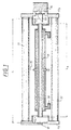
- the CO 2 laser (1) according to FIG. 1 consists of components known per se.
- a ceramic waveguide (11) of length L K , a coupling mirror (12) at a distance d 1 and a grating (13) at a distance d 2 form the laser resonator.
- the resonator length L can be adjusted with a piezoelectric actuator (14).
- the excitation takes place via an HF line (15), water cooling (16) is provided and the whole is arranged in a stable housing (17).
- the grating (13) is designed, essentially by the number of grating lines and thus the resolution, that only the two desired lines Lambda 1 , Lambda 2 can oscillate (optimal line density approx. 150 lines / mm, Littrow angle 54.1 °, reflection efficiency in 1st order (ie with autocollimation) approx. 98%).
- the alternating emission is achieved (cf. 2) i), 2) ii)) by sinusoidally changing the resonator length L im Range of a quarter wavelength, here approx. ⁇ 2.7 ⁇ m, with the piezoelectric actuator (14), which is the grid (13) linear in the direction of the optical axis of the laser (1) shifts.
- the laser gas is a common mixture of He, 13 CO 2 as a laser-active gas, N 2 and Xe, the gas pressure is approx. 120 mbar and the coupled RF power is in the order of 40 - 70 W.
- Internal losses in the resonator are primarily caused by the Littrow grating (13) (reflection, scattering, absorption) and the waveguide (11) are determined and amount to approx. 3-5%.
- FIG. 2 shows a typical signature of the 13 CO 2 laser used, ie the output power P out as a function of the change Delta L of the resonator length L.
- a bias voltage (U AP ) is applied to the piezoelectric actuator (14) so that the signature is at a minimum.
- a sine modulation U mod is applied , as a result of which the voltage at the piezo element is varied up and down and the laser (1) is moved to the maximum of the power curve of lambda 1 and then to the maximum of lambda 2 . Deviations from the maximum are permitted.
- the bias voltage U AP is actively stabilized by the programmable computer (57) to the working point. According to the modulation frequency, a signal sequence results that corresponds to the signature form.
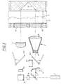
- FIG. 3 shows the optical structure of an NH 3 detector for flue gas in a flue gas duct (32).
- a reference detector D1
- the transmission optics (2) is a telescope with two lenses (21) and (22) for beam expansion.
- the laser beam enters the flue gas channel (32) through a closing window (25) and crosses the measuring section (3).
- a retroreflector (31) ensures the beam reversal to the end window (41).
- the measuring section of approximately 1 m to 20 m in length, which can also be folded several times in the flue gas channel (32) (cf.
- the laser beam is specifically weakened and reaches the measuring detector (D2), which is an MCT detector, via the receiving optics in the form of a converging lens (4).
- MCT detectors are special photoresistors made of mercury (mercury) -cadmium telluride, which are thermoelectrically cooled to approx. - 60 ° C and have very short response times.
- the signals from the reference (D1) and measuring detector (D2) are fed to the evaluation device (5).
- the laser beam can be weakened to protect the detectors by means of a pivotable filter (24), for example to 2 per mille power.
- the laser radiation can pass through two insertable gold mirrors (62, 63) directly to the measuring detector (D2) in order to compare the evidence using (D1 and D2) ("zero measurement”).
- a calibrated cell (61) with a known NH 3 content can then be introduced to calibrate the absorption strength at the two wavelengths Lambda 1 , Lambda 2 ("reference measurement").
- Figure 4 shows the measurement signal thus generated at the measurement detector.
- the zero point is reached on the basis of the signature described with FIG. 2.
- the times t 1 and t 2 each show the limits of the integration time, see below.
- the indentations in the middle of the signal curves arise when the modulation voltage U mod slightly exceeds the maxima of the signature (FIG. 2). It is shown that the detectors (D1, D2) have a zero position shifted by an offset due to the AC coupling, which is why the offset control (53, 53R) is provided (see below).
- FIG. 5 shows a block diagram of the evaluation circuit (5) together with the core elements of the optical structure - the same reference numerals designate the same parts as in the figure 1 and Figure 3 - and other circuit parts.
- the evaluation circuit contains for both detectors (D1, D2) one AC coupling each (51, 51R), one Amplifier (52, 52R), an offset control (53, 53R) and an integration device (55, 55R).
- the measuring detector (D2) is arranged immediately in front of the integration device (55) a programmable adjustable amplification circuit (54), e.g. with switching levels 100, 100, 1000 times. With a very high dynamic range, the detector can thus the integration device (55) and the subsequent one Analog-digital converter (56) for measuring and Reference signal serves at the same time, much easier be designed.
- a programmable computer (57) evaluates the digitized signals from the measuring beam path (3) for lambda 1 and lambda 2 and from the reference detector (D1) for lambda 1 and lambda 2 in a known manner (cf. US Pat. No. 5,002,391) and generates concentration information.
- An entered or externally stored look-up table (571) for the ammonia absorption allows the NH 3 concentration to be specified in any units.
- Data that are recorded by one or more sensors (7) in the flue gas channel (32) via pressure, temperature or other factors, for example the carbon dioxide concentration, can also be taken into account, so that the absolute concentration of ammonia can be indicated.
- a monitor (8) is for example used for data output. intended.
- the programmable computer (57) also controls the laser modulation via the piezoelectric adjustment device (14) and the offset control (53, 53R) as well as the adjustable Amplification circuit (54) and the timing of Integration (55, 55R) and can be used for other needs Tasks programmed and connected via interfaces become.
- the laser radiation arrives after passing through the measuring section (3) on the measuring detector (D2), a small part of the Radiation is directed through the beam splitter (23) Reference detector (D1) passed.
- the detector signals from (D1) and (D2) are amplified, namely AC-coupled, because a DC offset signal due to the required bias current of the detectors arises.
- the AC coupling (51, 51R), the 0V line fluctuates depending the waveform and signal amplitude. Since the measurement / reference signals to be evaluated through integration is one Connection of the signals to the 0V level necessary. This happens in the offset control (53, 53R) using sample & hold: If the modulation signal has a zero crossing, you get a signal minimum.
- the operating point (U AP ) of the laser (1) and the modulation voltage U mod are determined automatically. Since a constructive design ensures that the laser (1) only emits on the two desired lines lambda 1 , lambda 2 , a spectrum analyzer for checking the wavelength is unnecessary.
- the light attenuation measured at the wavelength Lambda2 or transmission that is unaffected by ammonia used to determine the smoke density in the measuring volume (3) become. This is exactly possible if the components of the Exhaust gas / smoke flow itself and the extinction coefficient of smoke are known.
- the long wavelength used in the infrared is advantageous because of the low Scattering recorded relatively large measuring lengths and smoke densities can be. A particular advantage is that this additional measurement only through appropriate programming of the computer (57) is obtained.
- the description of the invention using a specific example does not imply any restriction, and numerous modifications are possible. It is important that the design according to the invention makes it possible to do without choppers or similar additional light modulators in the substance detection arrangement, since the signature of the laser (1) ensures a reliable zero crossing of the laser intensity.
- the sine modulation of the laser light can be processed by the detectors (D1) and (D2) and the evaluation circuit (5) true to form, in contrast to rectangular modulation, without losses in the Fourier decomposition or in the frequency response. This enables the integration of the signals and thus the high utilization of laser energy for signal generation. Rectangular modulation with sample-and-hold signal processing, on the other hand, has to disregard a large part of the laser pulse.
- a reference cell with a calibrated NH 3 content is also not constantly measured with its own detector. It is sufficient to occasionally introduce them for calibration purposes and then use the existing measuring detector (D2).
Landscapes
- Physics & Mathematics (AREA)
- Chemical & Material Sciences (AREA)
- Engineering & Computer Science (AREA)
- Health & Medical Sciences (AREA)
- Life Sciences & Earth Sciences (AREA)
- Optics & Photonics (AREA)
- Electromagnetism (AREA)
- Spectroscopy & Molecular Physics (AREA)
- Analytical Chemistry (AREA)
- Biochemistry (AREA)
- General Health & Medical Sciences (AREA)
- General Physics & Mathematics (AREA)
- Immunology (AREA)
- Pathology (AREA)
- Food Science & Technology (AREA)
- Plasma & Fusion (AREA)
- Medicinal Chemistry (AREA)
- Combustion & Propulsion (AREA)
- Investigating Or Analysing Materials By Optical Means (AREA)
- Lasers (AREA)
Description
- Fig. 1
- schematisch den Aufbau eines erfindungsgemäßen Lasers (Beispiel);
- Fig. 2
- die Signatur eines erfindungsgemäßen Lasers;
- Fig. 3
- ein schematisches Beispiel für den optischen Aufbau einer Anordnung zum Stoffnachweis;
- Fig. 4
- den Verlauf des Signals am Meßdetektor einer Anordnung nach Fig. 3;
- Fig. 5
- ein Blockschaltbild einer Schaltung für eine erfindungsgemäße Anordnung zum Stoffnachweis.
- N =
- ganze Zahl (Unterschied in der Anzahl der Halbwellen Lambda/2 von Linie 1 und 2).
- FSR =
- Freier Spektralbereich: c/2L (c = Lichtgeschw., L = Resonatorlänge)
R(16), Lambda1 = 10,800 µm: f1 = 27758500.36 MHz und
R(18), Lambda2 = 10,784 µm: f2 = 27799764.18 MHz (vergleiche US 5 002 391).

Claims (19)
- Gaslaser, der durch sinusförmige Verschiebung eines Resonatorspiegels oder eines Gitters (13) bei zwei verschiedenen Wellenlängen (Lambda1, Lambda2) emittiert, dadurch gekennzeichnet, daß durch geeignete Dimensionierung eines Gitters (13) hinsichtlich Gitterstruktur und Winkellage, des Auskoppelgrads des Auskoppelspiegels (12), der Resonatorlänge (L) und der Gaszusammensetzung der Laser in zwei nebeneinanderliegenden Intervallen der Resonatorlänge (L) bei den zwei gewünschten Wellenlängen (Lambda1 und Lambda2) emittiert und am Übergang zwischen den zwei Intervallen die Laseremission unterbunden ist, und daß die sinusförmige Modulation der Resonatorlänge (L) im wesentlichen symmetrisch um diesen Übergang liegt.
- Gaslaser nach Anspruch 1, dadurch gekennzeichnet, daß er ein CO2-Laser mit einem Gitter in Littrow-Anordnung ist.
- Gaslaser nach Anspruch 1 oder Anspruch 2, dadurch gekennzeichnet, daß die Resonatorlänge (L) nach L = (n + 1/2) · L0 bestimmt ist, wobei n ganzzahlig ist und L0 die kleinste Länge ist, bei der zugleich für beide Wellenlängen (Lambda1, Lambda2), bei welchen der Laser (1) emittiert, Resonanz gegeben ist.
- Gaslaser nach Anspruch 2 oder 3, dadurch gekennzeichnet, daß er das Isotop 13C enthält und bei den Linien R (16) mit der Wellenlänge Lambda1 = 10,800 µm und R (18) mit Lambda2 = 10,784 µm emittiert.
- Gaslaser nach mindestens einem der Ansprüche 1 - 4, dadurch gekennzeichnet, daß ein piezoelektrisches Stellelement (14) zur linearen Verschiebung des Gitters (13) in Richtung der Resonatorachse vorgesehen ist und damit die emittierte Wellenlänge (Lambda1, Lambda2) bestimmt wird.
- Verwendung eines Gaslasers (1) nach mindestens einem der Ansprüche 1 - 5 in einer Anordnung zum Stoffnachweis durch unterschiedliche Absorption von Licht zweier Wellenlängen (Lambda1, Lambda2).
- Verwendung eines Gaslasers (1) nach Anspruch 6 gekennzeichnet durch den Nachweis von Spurengas in Gas, insbesondere von NH3 in Rauchgas.
- Anordnung zum Stoffnachweis mit einer 2-Wellenlängen-Laserlichtquelle (1),einer Modulationseinrichtung (14) zum Verstellen der Resonatorlänge (L) und einer Referenz-Detektionseinrichtung (D1) zur Erfassung der momentanen Laserleistung,einer Sendeoptik (2)einer sich anschließenden Meßstrecke (3), welche den nachzuweisenden Stoff enthält,einer Empfangsoptik (4) für das Laserlicht, das die Meßstrecke passiert hat, und einem sich anschließenden Meßdetektor (D2)und einer Auswerteeinrichtung (5), welche das Verhältnis der Lichtabsorption in der Meßstrecke (3) bei den zwei Wellenlängen (Lambda1, Lambda2) und daraus die Konzentration des nachzuweisenden Stoffes in der Meßstrecke (3) bestimmt, dadurch gekennzeichnet, daß die 2-Wellenlängen-Laserlichtquelle (1) ein Laser nach einem oder mehreren der Ansprüche 1 - 5 ist.
- Anordnung nach Anspruch 8, dadurch gekennzeichnet, daß die Meßstrecke (3) offen ist und einen Reflektor (31) enthält.
- Eine Anordnung nach Anspruch 8 oder Anspruch 9, dadurch gekennzeichnet, daß zum Zweck einer Referenzmessung eine Zelle (61) mit bekannter Konzentration des nachzuweisenden Stoffs in den Strahlengang eingebracht werden kann.
- Anordnung nach Anspruch 9 oder 10, dadurch gekennzeichnet, daß die Meßstrecke (3) in einem Rauchgaskanal (32) liegt und der nachzuweisende Stoff NH3 ist.
- Anordnung nach mindestens einem der Ansprüche 8 - 11, dadurch gekennzeichnet, daß Mittel (24) zur Einstellung der in die Meßstrecke (3) eingestrahlten Laserleistung zur Anpassung an die Konzentration des nachzuweisenden Stoffs oder des Untergrunds vorhanden sind.
- Anordnung nach mindestens einem der Ansprüche 8 - 12, dadurch gekennzeichnet, daß die Anordnung chopperlos aufgebaut ist mit einem dauernd lichtdurchgängigen Strahlungsweg von der Laserlichtquelle (1) zum Meßdetektor.
- Anordnung nach mindestens einem der Ansprüche 8 - 13, dadurch gekennzeichnet, daß höchstens zwei Detektoren für das Laserlicht vorhanden sind.
- Anordnung nach mindestens einem der Ansprüche 8 - 14, dadurch gekennzeichnet, daß der Meßdetektor (D2) ein MCT-Detektor ist.
- Anordnung nach mindestens einem der Ansprüche 8 - 15, dadurch gekennzeichnet, daß die Auswerteeinrichtung (5) eine Wechselstromkopplung (51, 51R) des Referenz-(D1) und des Meßdetektors (D2) eine Verstärkungsschaltung (52, 52R, 54) zur Verstärkung der Signale des Referenz-(D1) und Meßdetektors (D2) und eine nachgeschaltete Integrationseinrichtung (55, 55R) enthält, sowie einen anschließenden Analog-Digital-Wandler (56) und einen programmierbaren Rechner (57).
- Anordnung nach Anspruch 16, dadurch gekennzeichnet, daß die Integrationseinrichtung (55, 55R) so ausgebildet ist, daß sie das vom Meßdetektor (D2) aufgenommene Signal jeweils über den überwiegenden Teil (t1 - t2) des Zeitintervalls, in dem der Gaslaser (1) bei einer Wellenlänge (Lambda1, Lambda2) emittiert, aufintegriert.
- Anordnung nach Anspruch 16 oder 17, dadurch gekennzeichnet, daß sie so ausgebildet ist, daß die Verstärkungsschaltung (54) in ihrem Verstärkungsfaktor abhängig vom Signal des Meßdetektors (D2) automatisch verstellt wird.
- Anordnung nach mindestens einem der Ansprüche 8 - 18, dadurch gekennzeichnet, daß die Meßstrecke (3) in einem Rauchgaskanal (32) liegt und der nachzuweisende Stoff NH3 ist, und daß die Auswerteeinrichtung (5) so ausgebildet ist, daß aus den bei der Wellenlänge (Lambda2), bei der Ammoniak nicht absorbiert, gewonnenen Absorptionsdaten zusätzlich ein Meßwert für die Rauchdichte in der Meßstrecke (3) bestimmt und ausgegeben wird.
Applications Claiming Priority (2)
| Application Number | Priority Date | Filing Date | Title |
|---|---|---|---|
| DE4402054A DE4402054A1 (de) | 1994-01-25 | 1994-01-25 | Gaslaser und Gasnachweis damit |
| DE4402054 | 1994-01-25 |
Publications (2)
| Publication Number | Publication Date |
|---|---|
| EP0677733A1 EP0677733A1 (de) | 1995-10-18 |
| EP0677733B1 true EP0677733B1 (de) | 2001-04-11 |
Family
ID=6508612
Family Applications (1)
| Application Number | Title | Priority Date | Filing Date |
|---|---|---|---|
| EP95100163A Expired - Lifetime EP0677733B1 (de) | 1994-01-25 | 1995-01-07 | Gaslaser und Gasnachweis damit |
Country Status (6)
| Country | Link |
|---|---|
| US (1) | US5544186A (de) |
| EP (1) | EP0677733B1 (de) |
| JP (1) | JPH0843306A (de) |
| CA (1) | CA2140995A1 (de) |
| DE (2) | DE4402054A1 (de) |
| DK (1) | DK0677733T3 (de) |
Families Citing this family (28)
| Publication number | Priority date | Publication date | Assignee | Title |
|---|---|---|---|---|
| IL121793A (en) * | 1997-09-17 | 2008-06-05 | Lewis Coleman | Isotopic gas analyzer |
| AT411298B (de) * | 2001-09-18 | 2003-11-25 | Gerhard Mag Totschnig | Verfahren zur laser-absorptionsspektroskopie und einrichtungen zur durchführung dieses verfahrens |
| JP4522882B2 (ja) * | 2005-02-15 | 2010-08-11 | 浜松ホトニクス株式会社 | 吸収計測装置 |
| US8021469B2 (en) * | 2005-07-14 | 2011-09-20 | Access Business Group International Llc | Control methods for an air treatment system |
| US7808640B2 (en) * | 2008-07-30 | 2010-10-05 | Honeywell International Inc. | Photoacoustic spectroscopy system |
| US8327686B2 (en) * | 2010-03-02 | 2012-12-11 | Li-Cor, Inc. | Method and apparatus for the photo-acoustic identification and quantification of analyte species in a gaseous or liquid medium |
| US8269972B2 (en) | 2010-06-29 | 2012-09-18 | Honeywell International Inc. | Beam intensity detection in a cavity ring down sensor |
| US8437000B2 (en) | 2010-06-29 | 2013-05-07 | Honeywell International Inc. | Multiple wavelength cavity ring down gas sensor |
| US8322191B2 (en) | 2010-06-30 | 2012-12-04 | Honeywell International Inc. | Enhanced cavity for a photoacoustic gas sensor |
| JP2014516405A (ja) * | 2011-03-25 | 2014-07-10 | ユニバーシティ オブ ヴァージニア パテント ファウンデーション | 分光装置に適合可能なセルデザイン |
| US8945936B2 (en) | 2011-04-06 | 2015-02-03 | Fresenius Medical Care Holdings, Inc. | Measuring chemical properties of a sample fluid in dialysis systems |
| US8665442B2 (en) * | 2011-08-18 | 2014-03-04 | Li-Cor, Inc. | Cavity enhanced laser based isotopic gas analyzer |
| US8659759B2 (en) | 2011-08-25 | 2014-02-25 | Li-Cor, Inc. | Laser based cavity enhanced optical absorption gas analyzer |
| EP2564973B1 (de) * | 2011-09-05 | 2014-12-10 | ALLTEC Angewandte Laserlicht Technologie Gesellschaft mit beschränkter Haftung | Markierungsvorrichtung mit mehreren Lasern und einem Mischungsdeflektorsmittel |
| EP2564972B1 (de) * | 2011-09-05 | 2015-08-26 | ALLTEC Angewandte Laserlicht Technologie Gesellschaft mit beschränkter Haftung | Markierungsvorrichtung mith mehreren Lasern, Deflektionmitteln und Telescopikmitteln für jeden Laserstrahl |
| EP2564976B1 (de) | 2011-09-05 | 2015-06-10 | ALLTEC Angewandte Laserlicht Technologie Gesellschaft mit beschränkter Haftung | Markierungsvorrichtung mit mindestens einem Gaslaser und einer Kühleinrichtung |
| ES2544269T3 (es) * | 2011-09-05 | 2015-08-28 | ALLTEC Angewandte Laserlicht Technologie Gesellschaft mit beschränkter Haftung | Aparato de marcado con una pluralidad de láseres de gas con tubos de resonancia y medios de deflexión ajustables individualmente |
| DK2565994T3 (en) | 2011-09-05 | 2014-03-10 | Alltec Angewandte Laserlicht Technologie Gmbh | Laser device and method for marking an object |
| EP2565996B1 (de) | 2011-09-05 | 2013-12-11 | ALLTEC Angewandte Laserlicht Technologie Gesellschaft mit beschränkter Haftung | Lasergerät mit Lasereinheit und Flüssigkeitsbehälter für eine Kühlvorrichtung dieser Lasereinheit |
| EP2564975B1 (de) * | 2011-09-05 | 2014-12-10 | ALLTEC Angewandte Laserlicht Technologie Gesellschaft mit beschränkter Haftung | Markierungsvorrichtung mit mehreren Lasern und individuell justierbaren Deflektionsmitteln |
| EP2565673B1 (de) | 2011-09-05 | 2013-11-13 | ALLTEC Angewandte Laserlicht Technologie Gesellschaft mit beschränkter Haftung | Vorrichtung und Verfahren zum Markieren eines Objekts mit Hilfe eines Laserstrahls |
| US8659758B2 (en) | 2011-10-04 | 2014-02-25 | Li-Cor, Inc. | Laser based cavity enhanced optical absorption gas analyzer with laser feedback optimization |
| US9194742B2 (en) | 2012-11-02 | 2015-11-24 | Li-Cor, Inc. | Cavity enhanced laser based gas analyzer systems and methods |
| US8885167B2 (en) | 2012-11-02 | 2014-11-11 | Li-Cor, Inc. | Cavity enhanced laser based gas analyzer systems and methods |
| US20180202923A1 (en) * | 2015-07-17 | 2018-07-19 | Konica Minolta, Inc. | Gas Detection Device and Gas Detection Method |
| WO2017058901A1 (en) | 2015-09-28 | 2017-04-06 | Ball Aerospace & Technologies Corp. | Differential absorption lidar |
| US10168276B1 (en) | 2017-11-08 | 2019-01-01 | Itron, Inc. | Identifying targeted gaseous chemical compound |
| US10921245B2 (en) | 2018-06-08 | 2021-02-16 | Ball Aerospace & Technologies Corp. | Method and systems for remote emission detection and rate determination |
Family Cites Families (6)
| Publication number | Priority date | Publication date | Assignee | Title |
|---|---|---|---|---|
| US4471220A (en) * | 1981-12-21 | 1984-09-11 | Exxon Research And Engineering Co. | System for monitoring trace gaseous ammonia concentration in flue gases |
| GB2127537B (en) * | 1982-09-09 | 1986-09-10 | Laser Applic Limited | Gas detection apparatus |
| JPS61222289A (ja) * | 1985-03-28 | 1986-10-02 | Tokyo Gas Co Ltd | レ−ザ装置 |
| US4789989A (en) * | 1987-09-25 | 1988-12-06 | General Dynamics Corp./Space Systems Div. | Solar simulator employing flexible-optics |
| DE3741026A1 (de) * | 1987-12-03 | 1989-06-15 | Muetek Laser Und Opto Elektron | Verfahren und system zur (spuren-) gasanalyse |
| DE4203225C2 (de) * | 1992-02-05 | 1994-06-09 | Deutsche Forsch Luft Raumfahrt | Wellenleiterlaser |
-
1994
- 1994-01-25 DE DE4402054A patent/DE4402054A1/de not_active Ceased
-
1995
- 1995-01-07 DK DK95100163T patent/DK0677733T3/da active
- 1995-01-07 DE DE59509167T patent/DE59509167D1/de not_active Expired - Fee Related
- 1995-01-07 EP EP95100163A patent/EP0677733B1/de not_active Expired - Lifetime
- 1995-01-24 CA CA002140995A patent/CA2140995A1/en not_active Abandoned
- 1995-01-25 JP JP7027763A patent/JPH0843306A/ja active Pending
- 1995-01-25 US US08/378,017 patent/US5544186A/en not_active Expired - Fee Related
Non-Patent Citations (1)
| Title |
|---|
| W. J. WITTEMAN: "The CO2 Laser", 1987, SPRINGER, BERLIN, 987 * |
Also Published As
| Publication number | Publication date |
|---|---|
| EP0677733A1 (de) | 1995-10-18 |
| JPH0843306A (ja) | 1996-02-16 |
| DE4402054A1 (de) | 1995-07-27 |
| CA2140995A1 (en) | 1995-07-26 |
| DE59509167D1 (de) | 2001-05-17 |
| DK0677733T3 (da) | 2001-07-30 |
| US5544186A (en) | 1996-08-06 |
Similar Documents
| Publication | Publication Date | Title |
|---|---|---|
| EP0677733A1 (de) | Gaslaser und Gasnachweis damit | |
| DE19611290C2 (de) | Gassensor | |
| EP0874233B1 (de) | Gassensor zur selektiven Detektion von Gasen | |
| EP3455612B1 (de) | Messeinrichtung und verfahren zur erfassung unterschiedlicher gase und gaskonzentrationen | |
| DE19713928C1 (de) | Meßvorrichtung zur Infrarotabsorption | |
| EP2520924A1 (de) | Verfahren und Messanordnung zur Verbesserung der Signalauflösung bei der Gasabsorptionsspektroskopie | |
| DE10015615C2 (de) | Gasmesssystem | |
| DE3741026A1 (de) | Verfahren und system zur (spuren-) gasanalyse | |
| EP2132553A1 (de) | Zylindrischer photoakustischer detektor mit anregung der zweiten azimutalen resonanz | |
| DE2537237A1 (de) | Laserabsorptionsspektrometer und verfahren der laserabsorptionsspektroskopie | |
| WO2000075640A1 (de) | Analysegerät | |
| DE2616377A1 (de) | Verfahren zur kontinuierlichen erzeugung von wellen kohaerenter anti-stokes- schwingungsspektren | |
| DE3513035A1 (de) | System zum nachweis kleiner teilchen | |
| DE4446723C2 (de) | Vorrichtung und Verfahren zur Messung der Konzentration eines Gases | |
| DE10255022A1 (de) | Resonatorverstärktes Absorptions-Spektrometer | |
| DE19634191B4 (de) | Vorrichtung und Verfahren zur Gasdetektion | |
| DE102014226487A1 (de) | FTIR-Spektrometer mit Stabilisierung des Referenzlasers über eine natürliche Absorptionslinie | |
| DE9420231U1 (de) | Vorrichtung zum Detektieren eines Gases | |
| DE19525415C2 (de) | Verfahren und Vorrichtung zur Bestimmung der Wasserdampfkonzentration bzw. des Taupunktes | |
| DE3734401C2 (de) | ||
| DE102005049522B3 (de) | Gassensoranordnung | |
| DE3002558C2 (de) | Einrichtung zum Messen der Strahlungsleistung und der Strahlungsenergie von Lasern | |
| DE68907524T2 (de) | Elektrische Signalüberwachungsvorrichtung. | |
| WO2007014960A1 (de) | Anordnung zur bestimmung der gastemperatur | |
| WO2004008113A1 (de) | Absorptionsspektrometer und entsprechendes messverfahren |
Legal Events
| Date | Code | Title | Description |
|---|---|---|---|
| PUAI | Public reference made under article 153(3) epc to a published international application that has entered the european phase |
Free format text: ORIGINAL CODE: 0009012 |
|
| AK | Designated contracting states |
Kind code of ref document: A1 Designated state(s): CH DE DK FR GB IT LI SE |
|
| 17P | Request for examination filed |
Effective date: 19960315 |
|
| 17Q | First examination report despatched |
Effective date: 19980714 |
|
| GRAG | Despatch of communication of intention to grant |
Free format text: ORIGINAL CODE: EPIDOS AGRA |
|
| GRAG | Despatch of communication of intention to grant |
Free format text: ORIGINAL CODE: EPIDOS AGRA |
|
| GRAG | Despatch of communication of intention to grant |
Free format text: ORIGINAL CODE: EPIDOS AGRA |
|
| GRAH | Despatch of communication of intention to grant a patent |
Free format text: ORIGINAL CODE: EPIDOS IGRA |
|
| GRAH | Despatch of communication of intention to grant a patent |
Free format text: ORIGINAL CODE: EPIDOS IGRA |
|
| GRAA | (expected) grant |
Free format text: ORIGINAL CODE: 0009210 |
|
| AK | Designated contracting states |
Kind code of ref document: B1 Designated state(s): CH DE DK FR GB IT LI SE |
|
| REG | Reference to a national code |
Ref country code: CH Ref legal event code: EP |
|
| REF | Corresponds to: |
Ref document number: 59509167 Country of ref document: DE Date of ref document: 20010517 |
|
| ITF | It: translation for a ep patent filed | ||
| REG | Reference to a national code |
Ref country code: DK Ref legal event code: T3 |
|
| GBT | Gb: translation of ep patent filed (gb section 77(6)(a)/1977) |
Effective date: 20010710 |
|
| ET | Fr: translation filed | ||
| REG | Reference to a national code |
Ref country code: GB Ref legal event code: IF02 |
|
| PLBE | No opposition filed within time limit |
Free format text: ORIGINAL CODE: 0009261 |
|
| STAA | Information on the status of an ep patent application or granted ep patent |
Free format text: STATUS: NO OPPOSITION FILED WITHIN TIME LIMIT |
|
| 26N | No opposition filed | ||
| PGFP | Annual fee paid to national office [announced via postgrant information from national office to epo] |
Ref country code: SE Payment date: 20040105 Year of fee payment: 10 Ref country code: GB Payment date: 20040105 Year of fee payment: 10 |
|
| PGFP | Annual fee paid to national office [announced via postgrant information from national office to epo] |
Ref country code: DK Payment date: 20040106 Year of fee payment: 10 Ref country code: CH Payment date: 20040106 Year of fee payment: 10 |
|
| PGFP | Annual fee paid to national office [announced via postgrant information from national office to epo] |
Ref country code: DE Payment date: 20040108 Year of fee payment: 10 |
|
| PGFP | Annual fee paid to national office [announced via postgrant information from national office to epo] |
Ref country code: FR Payment date: 20040109 Year of fee payment: 10 |
|
| PG25 | Lapsed in a contracting state [announced via postgrant information from national office to epo] |
Ref country code: IT Free format text: LAPSE BECAUSE OF NON-PAYMENT OF DUE FEES;WARNING: LAPSES OF ITALIAN PATENTS WITH EFFECTIVE DATE BEFORE 2007 MAY HAVE OCCURRED AT ANY TIME BEFORE 2007. THE CORRECT EFFECTIVE DATE MAY BE DIFFERENT FROM THE ONE RECORDED. Effective date: 20050107 Ref country code: GB Free format text: LAPSE BECAUSE OF NON-PAYMENT OF DUE FEES Effective date: 20050107 |
|
| PG25 | Lapsed in a contracting state [announced via postgrant information from national office to epo] |
Ref country code: SE Free format text: LAPSE BECAUSE OF NON-PAYMENT OF DUE FEES Effective date: 20050108 |
|
| PG25 | Lapsed in a contracting state [announced via postgrant information from national office to epo] |
Ref country code: LI Free format text: LAPSE BECAUSE OF NON-PAYMENT OF DUE FEES Effective date: 20050131 Ref country code: DK Free format text: LAPSE BECAUSE OF NON-PAYMENT OF DUE FEES Effective date: 20050131 Ref country code: CH Free format text: LAPSE BECAUSE OF NON-PAYMENT OF DUE FEES Effective date: 20050131 |
|
| PG25 | Lapsed in a contracting state [announced via postgrant information from national office to epo] |
Ref country code: DE Free format text: LAPSE BECAUSE OF NON-PAYMENT OF DUE FEES Effective date: 20050802 |
|
| GBPC | Gb: european patent ceased through non-payment of renewal fee |
Effective date: 20050107 |
|
| EUG | Se: european patent has lapsed | ||
| REG | Reference to a national code |
Ref country code: DK Ref legal event code: EBP |
|
| REG | Reference to a national code |
Ref country code: CH Ref legal event code: PL |
|
| PG25 | Lapsed in a contracting state [announced via postgrant information from national office to epo] |
Ref country code: FR Free format text: LAPSE BECAUSE OF NON-PAYMENT OF DUE FEES Effective date: 20050930 |
|
| REG | Reference to a national code |
Ref country code: FR Ref legal event code: ST |