EP0675250B1 - Serrure, en particulier crémone ou similaire - Google Patents
Serrure, en particulier crémone ou similaire Download PDFInfo
- Publication number
- EP0675250B1 EP0675250B1 EP95100927A EP95100927A EP0675250B1 EP 0675250 B1 EP0675250 B1 EP 0675250B1 EP 95100927 A EP95100927 A EP 95100927A EP 95100927 A EP95100927 A EP 95100927A EP 0675250 B1 EP0675250 B1 EP 0675250B1
- Authority
- EP
- European Patent Office
- Prior art keywords
- handle
- driving
- slide
- rod connection
- displaced
- Prior art date
- Legal status (The legal status is an assumption and is not a legal conclusion. Google has not performed a legal analysis and makes no representation as to the accuracy of the status listed.)
- Expired - Lifetime
Links
Images


Classifications
-
- E—FIXED CONSTRUCTIONS
- E05—LOCKS; KEYS; WINDOW OR DOOR FITTINGS; SAFES
- E05C—BOLTS OR FASTENING DEVICES FOR WINGS, SPECIALLY FOR DOORS OR WINDOWS
- E05C9/00—Arrangements of simultaneously actuated bolts or other securing devices at well-separated positions on the same wing
- E05C9/02—Arrangements of simultaneously actuated bolts or other securing devices at well-separated positions on the same wing with one sliding bar for fastening when moved in one direction and unfastening when moved in opposite direction; with two sliding bars moved in the same direction when fastening or unfastening
- E05C9/021—Arrangements of simultaneously actuated bolts or other securing devices at well-separated positions on the same wing with one sliding bar for fastening when moved in one direction and unfastening when moved in opposite direction; with two sliding bars moved in the same direction when fastening or unfastening with rack and pinion mechanism
-
- E—FIXED CONSTRUCTIONS
- E05—LOCKS; KEYS; WINDOW OR DOOR FITTINGS; SAFES
- E05C—BOLTS OR FASTENING DEVICES FOR WINGS, SPECIALLY FOR DOORS OR WINDOWS
- E05C9/00—Arrangements of simultaneously actuated bolts or other securing devices at well-separated positions on the same wing
- E05C9/02—Arrangements of simultaneously actuated bolts or other securing devices at well-separated positions on the same wing with one sliding bar for fastening when moved in one direction and unfastening when moved in opposite direction; with two sliding bars moved in the same direction when fastening or unfastening
- E05C9/026—Arrangements of simultaneously actuated bolts or other securing devices at well-separated positions on the same wing with one sliding bar for fastening when moved in one direction and unfastening when moved in opposite direction; with two sliding bars moved in the same direction when fastening or unfastening comprising key-operated locks, e.g. a lock cylinder to drive auxiliary deadbolts or latch bolts
-
- E—FIXED CONSTRUCTIONS
- E05—LOCKS; KEYS; WINDOW OR DOOR FITTINGS; SAFES
- E05C—BOLTS OR FASTENING DEVICES FOR WINGS, SPECIALLY FOR DOORS OR WINDOWS
- E05C9/00—Arrangements of simultaneously actuated bolts or other securing devices at well-separated positions on the same wing
- E05C9/04—Arrangements of simultaneously actuated bolts or other securing devices at well-separated positions on the same wing with two sliding bars moved in opposite directions when fastening or unfastening
- E05C9/041—Arrangements of simultaneously actuated bolts or other securing devices at well-separated positions on the same wing with two sliding bars moved in opposite directions when fastening or unfastening with rack and pinion mechanism
-
- E—FIXED CONSTRUCTIONS
- E05—LOCKS; KEYS; WINDOW OR DOOR FITTINGS; SAFES
- E05C—BOLTS OR FASTENING DEVICES FOR WINGS, SPECIALLY FOR DOORS OR WINDOWS
- E05C9/00—Arrangements of simultaneously actuated bolts or other securing devices at well-separated positions on the same wing
- E05C9/04—Arrangements of simultaneously actuated bolts or other securing devices at well-separated positions on the same wing with two sliding bars moved in opposite directions when fastening or unfastening
- E05C9/047—Arrangements of simultaneously actuated bolts or other securing devices at well-separated positions on the same wing with two sliding bars moved in opposite directions when fastening or unfastening comprising key-operated locks, e.g. a lock cylinder to drive auxiliary deadbolts or latch bolts
-
- E—FIXED CONSTRUCTIONS
- E05—LOCKS; KEYS; WINDOW OR DOOR FITTINGS; SAFES
- E05C—BOLTS OR FASTENING DEVICES FOR WINGS, SPECIALLY FOR DOORS OR WINDOWS
- E05C9/00—Arrangements of simultaneously actuated bolts or other securing devices at well-separated positions on the same wing
- E05C9/06—Arrangements of simultaneously actuated bolts or other securing devices at well-separated positions on the same wing with three or more sliding bars
- E05C9/063—Arrangements of simultaneously actuated bolts or other securing devices at well-separated positions on the same wing with three or more sliding bars extending along three or more sides of the wing or frame
- E05C9/066—Locks for windows or doors specially adapted for tilt and turn
-
- E—FIXED CONSTRUCTIONS
- E05—LOCKS; KEYS; WINDOW OR DOOR FITTINGS; SAFES
- E05B—LOCKS; ACCESSORIES THEREFOR; HANDCUFFS
- E05B59/00—Locks with latches separate from the lock-bolts or with a plurality of latches or lock-bolts
Definitions
- the invention relates to a lock, in particular espagnolette lock or the like according to the generic term of Claim 1.
- Such a castle is known from the German Laid-open specification 39 01 957.
- a neutral position in which the pusher or a handle is usually horizontal
- the locked position the trap is closed and the Lockable latch. It is also in this position the connecting rod connecting slide in its closed position and the trap can no longer be closed, but blocked.
- An opening position is from one Realized intermediate position, in which the handle about 20 to 30 ° from the horizontal towards the Lock position is shifted. In this position the trap is closed.
- the invention has for its object a generic Locked regarding the locking position improve.
- the embodiment of the invention is now no longer recognizable whether the lock is in a neutral position or a locking position.
- the handle When actuated the handle first moves to the second handle position, which in the prior art the locking position assigned to the connecting rod connecting slide is.
- the trigger becomes shifted back to the first trigger position, which one in the prior art, the neutral position of the Espagnolette connecting slide is assigned.
- the lock remains in the locked position.
- the handle is moved back without taking the Espagnolette connecting slide.
- the pusher must be in again from the first position the second press position will be shifted. Only now takes place when the handle is moved back the connecting rod slide valve in the neutral position.
- Double actuation in the same direction once to reach the locking position and once to release the locking position gives the Locked an additional security.
- An advantageous one Further training of the castle provides that the castle has a key-operated latch, which only is lockable in the locking position and in all other drive rod positions are blocked. It it is also preferably provided that when locked Bolt also the lever handle is locked. It can also be provided that the connecting rod connecting slide by pushing the button in the opposite direction, from a first to a third press position, with simultaneous withdrawal of the trap into one a tilt assigned position is shiftable. It can be provided that the double actuation the handle is realized by a split nut. With the first actuation of the lever from the first lever position in the second press position are the two Coupled nut parts.
- the two nut parts When transitioning to the second The two nut parts are end-coupled, so that only a nut part after reaching the locking position according to a spring application in the first push position is moved back. In the second press actuation then only one nut part pivots and couples when reaching the second handle position again with the second nut part, so that both Nut parts are then spring loaded into the first lever position be relocated.
- the first nut part is preferred a central hub part, and the second nut part Segment of a ring gear. Both nut parts should preferably be coupled by a coupling member.
- the Sprocket which is assigned to a toothed segment part of the nut should be with a toothing of the drive rod comb.
- the coupling member is intended to enter the second pusher position either the clutch between Create or dissolve the nab compartment and ring gear. It is provided that the coupling part as on the ring gear seated two-armed swivel lever is formed.
- the one arm of the pivot lever forms a coupling pin that enters an opening of the hub part, in order to couple the two nut parts together in a rotationally fixed manner.
- the second arm of the coupling member should be with a interact in the housing of the control cam, which can be displaced transversely.
- the control curve is preferably assigned to a slide, which in the housing cover transversely to the direction of the faceplate is relocatable.
- the slide can be a second Have control curve on which a control pin of the Espagnolette connecting slide opens, so the slide to move to a position in which the control curve of the slide takes effect, which with the second Arm of the coupling member interacts.
- On the nut is an additional shoulder is provided, which is assigned to an arm of the hub part. With this Stop shoulder can enter the nut when entering First push position after relocation of the connecting rod slide in the locking position of the slide be moved back again, so that when the next one Actuate the pusher the coupling member back into the coupling position occurs.
- the connecting rod connecting slide a locking member is also assigned, which is in the neutral position and in a tilted position assigned position of the connecting rod connecting slide enters the trajectory of the bolt. Hereby the bolt is prevented from being actuated.
- a two-armed in the energy accumulator Rocker arm is assigned, which one arm in the Travel of the handle actuation spring protrudes and with its other end in a pocket of the tie tail or a tumbler that can be shifted with the bolt engages. If the bolt is now locked, the rocker arm pivots and reaches with one arm into the actuation path the trigger spring so that the trigger actuation Is blocked.
- There is an additional key lever in the lock case provided that with a shorter arm on a Control curve of the hub part of the nut slides and with a control arm of the drive rod connecting slide on a longer arm scans. The rocker arm is with his long arm cushioned towards the cuff.
- the short arm acts in the form of a ratchet with a locking projection of the hub part together, so that the handle in the locked position not in the third press position can be relocated.
- the rocker arm is moved so that the short arm behind the locking projection of the hub part, so that in the second press position, the actuation of the button is locked in the direction of the third trigger position.
- the espagnolette lock shown in the figures takes place preferably used for balcony doors or the like. Such doors can about a vertical axis be rotated and tilted about a horizontal axis become.
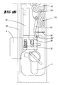
- the lock is functionally designed so that in a neutral position, the handle 6 horizontally runs ( Figure 1 and Figure 3). Is in this position bolt 4 closed and not lockable, the trap can either be hit on a Strike plate or closed by handle operation become.
- the handle is in one of FIG. 4 bring appropriate position (intermediate position). Around to come into the position shown in Figure 4 the handle can be shifted by about 20 to 25 °. At pressing the button further down into the second Pressure setting, as shown in FIG. 5, the trap 3 comes out again and becomes the connecting rod connecting slide 13 shifted upwards.
- a latch actuating arm 9 In the lock housing 1, which with a lock cover 2nd can be covered is pivotable about an axis 40 a latch actuating arm 9.
- the latch actuating arm has a control cam 11, with a projection 10.
- the free end 9 'of the latch actuating arm is between the trap head 3 and the trap tail 3 'form-fitting a, so that a pivoting of the latch actuating arm 9 is associated with a trap retreat.
- the pivoting of the latch actuating arm is controlled 9 by a control pin 12, which extends in the direction of the lock slidably guided in the lock housing 1 is located.
- the control pin 12 is fixed to the Espagnolette connecting slide 13 connected.
- the control pin 12 feels the cam 11 of the latch actuating arm from.
- a control pin or pin 20 arranged, which with a guided in the castle ceiling 2 Slider 7 cooperates.
- the slider 7 is in a recess 8 of the castle ceiling 2 out in a direction transverse to the direction of displacement of the connecting rod connecting slide 13.
- the slide 7 has one Control curve 7 'on by the control pin 20 at the Relocation of the connecting rod connecting slide is applied becomes. As a result, the slide 7 is in the direction shifted away from the cuff 18.
- the slide has a further control curve 7 ', which with an arm 28 '' of a coupling member 28 cooperates.
- the coupling member 28 is assigned to the nut. How in particular 11 and 12 can be seen, points the nut 23 on a hub part 30, which rotatably with the nut is connected. In a rectangular recess 24 of the hub part 30 is a press mandrel 29 for nut actuation insertable.
- the nut also has a ring gear part on which by means of the coupling member 28 the hub part 30 can be coupled.
- the ring gear part is there from the toothed segment sections 25 and 26.
- the coupling member On the Tooth segment 26, the coupling member is pivotable about a Pivot axis mounted.
- the coupling member 28 has the Shape of a two-armed lever, one arm 28 ' cooperates with the mentioned control curve 7 '.
- the opposite arm 28 ' forms a coupling pin from, he enters a corresponding recess 30 'of Hub part one.
- the arm 28 'in the recess 30' is the hub part 30 with the ring gear part 26, 25 rotatably connected when pivoting the coupling member 28 the arm 28 'emerges from the recess 30' out so that the two nut parts are uncoupled.
- the lock cylinder 5 Along with the closure of the bolt 4 by actuation the lock cylinder 5 becomes a locking lever 35 which is pivoted about an axis in the castle floor is pivoted.
- the locking lever 35 has a locking level 35 'on, which by pivoting against the Force of a spring 36 in the range of movement of the slide 42 is brought.
- the opposite free end the other swivel arm 35 "lies in a recess 38 a tumbler 37 of the bolt 4.
- the latch becomes the arm 35 "as well transversely displaced, accompanied by a pivoting of the Lever 35 so that the locking arm 35 'in the path of movement of the slider 42 is brought.
- FIG Position that is, with bolt 4 locked, actuation the handle 6 not possible.
- An actuating arm 33 is provided on the hub part 30, which in the position shown in Figure 8 Slider 7 applied and thus by a certain amount Amount shifted. For this purpose there is a stop on the arm 33 33 'provided, which against a corresponding counter-stop 7 '' '' kicks.
- the slider also points another control curve section 7 '' ', this control curve section prevents the connecting rod slide from moving back in the transition from that in FIG. 5 shown closed position in the shown in Figure 8 Closed position, the control pin 20 being there can hit the control surface 7 '' '.
Landscapes
- Engineering & Computer Science (AREA)
- Mechanical Engineering (AREA)
- Lock And Its Accessories (AREA)
- Immobilizing And Processing Of Enzymes And Microorganisms (AREA)
- Polysaccharides And Polysaccharide Derivatives (AREA)
Claims (12)
- Serrure à barres mobiles pour le déplacement d'au moins une barre mobile d'une porte, fenêtre ou analogue, avec un fouillot (23) actionnable par une poignée et un coulisseau de raccordement de barre mobile (13) déplaçable le long de la têtière, et avec un pêne demi-tour (3) rétractable transversalement par rapport à la têtière (18), le coulisseau de raccordement de barres mobiles (13) étant déplaçable par actionnement de la poignée, d'une première position de poignée dans une deuxième position de poignée, pour passer d'une position neutre à une position de verrouillage, où le pêne demi-tour (3) déployé dans la position neutre et dans la position de verrouillage prenant, dans une position intermédiaire située entre la position neutre et la position de verrouillage du coulisseau de raccordement de barres mobiles (13), une position rétractée, caractérisée en ce que - en partant de la position neutre - après avoir effectué un premier actionnement de la poignée, de la première position à la deuxième position de poignée, la poignée (6) est ramenée à sa première position de poignée sous l'effet d'un ressort (27), tandis que le coulisseau de raccordement de barres mobiles (13) reste dans la position de verrouillage, et ensuite, après répétition de l'actionnement de la poignée de la première à la deuxième position de poignée, il est ramené à la position neutre.
- Serrure à barres mobiles selon la revendication 1, caractérisée par un pêne dormant (4), en particulier actionnable par une clé, et qui ne peut être fermé préalablement que dans la position de verrouillage et est bloqué dans toutes les autres positions du coulisseau de raccordement de barres mobiles.
- Serrure à barres mobiles selon l'une ou plusieurs des revendications précédentes, caractérisée en ce que l'actionnement par poignée est bloqué lorsque le pêne dormant (4) est préfermé.
- Serrure à barres mobiles selon l'une ou plusieurs des revendications précédentes, caractérisée en ce que le coulisseau de raccordement de barres mobiles (13) est déplaçable par actionnement de la poignée dans le sens inverse d'une première position de poignée dans une troisième position de poignée avec rétraction simultanée du pêne demi-tour (3) dans une position associée à une position de basculement.
- Serrure à barres mobiles selon l'une ou plusieurs des revendications précédentes, caractérisée en ce que le fouillot (23) présente une partie de moyeu (30) centrale et une zone dentée (25, 26) susceptible d'y être accouplée au moyen d'un organe d'accouplement (28), la zone dentée s'engrenant avec une denture (31, 32) du genre d'une crémaillère appartenant à la barre mobile (13), l'organe d'accouplement (28) établissant ou respectivement cessant, dans la deuxième position. l'accouplement entre la partie de moyeu (30) et la zone dentée (25, 26).
- Serrure à barres mobiles selon l'une ou plusieurs des revendications précédentes, caractérisée en ce que l'organe d'accouplement est réalisé sous la forme d'un levier à deux bras (28) monté sur la partie de fouillot (25, 26) dentée, levier dont un bras (28') vient, dans la position d'accouplement, s'engager dans une ouverture (30') de la partie de moyeu (30), tandis que le deuxième bras (28") coopère avec une came de commande (27) déplaçable transversalement dans le boítier (2).
- Serrure à barres mobiles selon l'une ou plusieurs des revendications précédentes, caractérisée par une tige de commande (20), prévue sur le coulisseau de raccordement de barres mobiles (13) pour déplacer un coulisseau (7) constituant la came de commande (7'), lors du déplacement du coulisseau de raccordement de barres mobiles.
- Serrure à barres mobiles selon l'une ou plusieurs des revendications précédentes, caractérisée en ce que, lors du déplacement du coulisseau de raccordement de barres mobiles (13) dans la position de verrouillage, le coulisseau (7) est déplacé dans une première position de coulisseau susceptible de déplacer l'organe d'accouplement (28) en position de déblocage et, par un bras (33) associé à la partie de moyeu, lors du passage à la première position de poignée, est déplacé dans une deuxième position de coulisseau déplaçant l'organe d'accouplement (28) en position d'accouplement.
- Serrure à barres mobiles selon l'une ou plusieurs des revendications précédentes, caractérisée par un organe de blocage (22) associé au coulisseau de raccordement de barres mobiles (13) et situé sur la trajectoire de déplacement du pêne dormant (4), dans la position associée à la position neutre et à la position de basculement, du coulisseau de raccordement de barres mobiles (13).
- Serrure à barres mobiles selon l'une ou plusieurs des revendications précédentes, caractérisée par un organe d'accumulation de forces (34) susceptible d'être chargé ou armé lors de l'actionnement de la poignée par le fouillot (23).
- Serrure à barres mobiles selon l'une ou plusieurs des revendications précédentes, caractérisée en ce que l'organe d'accumulation de forces (34) présente un levier de blocage (35) accouplé au pêne demi-tour (3), qui bloque l'actionnement de l'organe d'accumulation de forces (34) lorsque le pêne dormant est sorti.
- Serrure à barres mobiles selon l'une ou plusieurs des revendications précédentes, caractérisée par un levier basculant (15) qui est pivoté dans la position de verrouillage du coulisseau de raccordement de barres mobiles (13), et qui, dans la position de verrouillage, coopère, par un premier bras (15'), avec une saillie d'encliquetage (39') du fouillot (23), de manière qu'un actionnement de la poignée dans la troisième position de poignée soit bloqué.
Applications Claiming Priority (2)
| Application Number | Priority Date | Filing Date | Title |
|---|---|---|---|
| DE4409439 | 1994-03-19 | ||
| DE4409439A DE4409439A1 (de) | 1994-03-19 | 1994-03-19 | Schloß, insbesondere Treibstangenschloß oder dergleichen |
Publications (2)
| Publication Number | Publication Date |
|---|---|
| EP0675250A1 EP0675250A1 (fr) | 1995-10-04 |
| EP0675250B1 true EP0675250B1 (fr) | 1999-03-17 |
Family
ID=6513255
Family Applications (1)
| Application Number | Title | Priority Date | Filing Date |
|---|---|---|---|
| EP95100927A Expired - Lifetime EP0675250B1 (fr) | 1994-03-19 | 1995-01-25 | Serrure, en particulier crémone ou similaire |
Country Status (3)
| Country | Link |
|---|---|
| EP (1) | EP0675250B1 (fr) |
| AT (1) | ATE177814T1 (fr) |
| DE (2) | DE4409439A1 (fr) |
Families Citing this family (2)
| Publication number | Priority date | Publication date | Assignee | Title |
|---|---|---|---|---|
| AT410961B (de) * | 2001-08-22 | 2003-09-25 | Roto Frank Eisenwaren | Mehrriegelschloss |
| CN101008297B (zh) * | 2007-01-26 | 2010-10-13 | 庄子平 | 一种组合门锁 |
Family Cites Families (4)
| Publication number | Priority date | Publication date | Assignee | Title |
|---|---|---|---|---|
| FR2025272A6 (fr) * | 1969-03-08 | 1970-09-04 | Drevet Et Cie | |
| US5265920A (en) * | 1988-09-16 | 1993-11-30 | Aug. Winkaus GmbH & Co. KG | Drive rod lock |
| DE3901957C2 (de) * | 1989-01-24 | 1999-04-01 | Fliether Karl Gmbh & Co | Treibstangenverschluß, insbesondere für Balkontüren |
| DE4041537A1 (de) * | 1990-12-22 | 1992-06-25 | Fliether Karl Gmbh & Co | Treibstangenverschluss |
-
1994
- 1994-03-19 DE DE4409439A patent/DE4409439A1/de not_active Withdrawn
-
1995
- 1995-01-25 AT AT95100927T patent/ATE177814T1/de not_active IP Right Cessation
- 1995-01-25 EP EP95100927A patent/EP0675250B1/fr not_active Expired - Lifetime
- 1995-01-25 DE DE59505346T patent/DE59505346D1/de not_active Expired - Fee Related
Also Published As
| Publication number | Publication date |
|---|---|
| ATE177814T1 (de) | 1999-04-15 |
| EP0675250A1 (fr) | 1995-10-04 |
| DE4409439A1 (de) | 1995-09-21 |
| DE59505346D1 (de) | 1999-04-22 |
Similar Documents
| Publication | Publication Date | Title |
|---|---|---|
| EP0796968B1 (fr) | Dispositif de fermeture | |
| EP2951369B1 (fr) | Serrure anti-panique | |
| EP1557514B1 (fr) | Crémone-serrure pour porte à double battants avec fonction anti-panique | |
| DE4324300C2 (de) | Antipanik-Türschloß | |
| DE8909801U1 (de) | Treibstangenschloß | |
| EP1049845B1 (fr) | Serrure a pene demi-tour faisant saillie hors du boitier de ladite serrure | |
| DE3505379C1 (de) | Treibstangenschloß | |
| EP0945572B1 (fr) | Ensemble de serrure de porte, de préférence crémone-serrure | |
| DE19626745C1 (de) | Selbstverriegelndes Panikschloß | |
| DE19607403A1 (de) | Treibstangenverschluß | |
| DE102004012108B4 (de) | Treibstangenschloss für Türen, Fenster oder dergleichen mit Panikfunktion und Mehrpunktverriegelung | |
| EP0954667B1 (fr) | Serrure a pene demi-tour pour porte ou fenetre | |
| EP1020594B1 (fr) | Crémone | |
| EP1020597B1 (fr) | Serrure à crémone avec une serrure principal et une serrure complémentaire | |
| DE102015000606A1 (de) | Verriegelungsvorrichtung für einen schwenkbar gelagerten Flügel | |
| DE4114007C2 (de) | Treibstangenverschluß | |
| EP0675250B1 (fr) | Serrure, en particulier crémone ou similaire | |
| DE3931101C2 (fr) | ||
| DE19822951B4 (de) | Schloss mit Falle und Hilfsfalle | |
| EP0381820B1 (fr) | Crémone | |
| DE202007016091U1 (de) | Treibstangenschloss | |
| EP0974721B1 (fr) | Serrure à plusieurs pênes | |
| WO1990004694A1 (fr) | Serrure a verrouillage automatique | |
| EP0990758A2 (fr) | Serrure additionelle pour crémone | |
| EP2322744A1 (fr) | Serrure, serrure à crochet pivotant et système de verrouillage, notamment pour le verrouillage à plusieurs points d'une porte ou d'une fenêtre |
Legal Events
| Date | Code | Title | Description |
|---|---|---|---|
| PUAI | Public reference made under article 153(3) epc to a published international application that has entered the european phase |
Free format text: ORIGINAL CODE: 0009012 |
|
| AK | Designated contracting states |
Kind code of ref document: A1 Designated state(s): AT BE CH DE DK ES FR GB GR IE IT LI LU MC NL PT SE |
|
| RAX | Requested extension states of the european patent have changed |
Free format text: LT PAYMENT 950127;SI PAYMENT 950127 |
|
| 17P | Request for examination filed |
Effective date: 19960206 |
|
| 17Q | First examination report despatched |
Effective date: 19970528 |
|
| GRAG | Despatch of communication of intention to grant |
Free format text: ORIGINAL CODE: EPIDOS AGRA |
|
| GRAG | Despatch of communication of intention to grant |
Free format text: ORIGINAL CODE: EPIDOS AGRA |
|
| GRAH | Despatch of communication of intention to grant a patent |
Free format text: ORIGINAL CODE: EPIDOS IGRA |
|
| GRAH | Despatch of communication of intention to grant a patent |
Free format text: ORIGINAL CODE: EPIDOS IGRA |
|
| RAP1 | Party data changed (applicant data changed or rights of an application transferred) |
Owner name: KARL FLIETHER GMBH & CO. |
|
| GRAA | (expected) grant |
Free format text: ORIGINAL CODE: 0009210 |
|
| AK | Designated contracting states |
Kind code of ref document: B1 Designated state(s): AT BE CH DE DK ES FR GB GR IE IT LI LU MC NL PT SE |
|
| AX | Request for extension of the european patent |
Free format text: LT PAYMENT 950127;SI PAYMENT 950127 |
|
| LTIE | Lt: invalidation of european patent or patent extension | ||
| PG25 | Lapsed in a contracting state [announced via postgrant information from national office to epo] |
Ref country code: SE Free format text: THE PATENT HAS BEEN ANNULLED BY A DECISION OF A NATIONAL AUTHORITY Effective date: 19990317 Ref country code: IT Free format text: LAPSE BECAUSE OF FAILURE TO SUBMIT A TRANSLATION OF THE DESCRIPTION OR TO PAY THE FEE WITHIN THE PRESCRIBED TIME-LIMIT;WARNING: LAPSES OF ITALIAN PATENTS WITH EFFECTIVE DATE BEFORE 2007 MAY HAVE OCCURRED AT ANY TIME BEFORE 2007. THE CORRECT EFFECTIVE DATE MAY BE DIFFERENT FROM THE ONE RECORDED. Effective date: 19990317 Ref country code: GR Free format text: LAPSE BECAUSE OF NON-PAYMENT OF DUE FEES Effective date: 19990317 Ref country code: GB Free format text: LAPSE BECAUSE OF NON-PAYMENT OF DUE FEES Effective date: 19990317 Ref country code: FR Free format text: LAPSE BECAUSE OF FAILURE TO SUBMIT A TRANSLATION OF THE DESCRIPTION OR TO PAY THE FEE WITHIN THE PRESCRIBED TIME-LIMIT Effective date: 19990317 Ref country code: ES Free format text: THE PATENT HAS BEEN ANNULLED BY A DECISION OF A NATIONAL AUTHORITY Effective date: 19990317 |
|
| REF | Corresponds to: |
Ref document number: 177814 Country of ref document: AT Date of ref document: 19990415 Kind code of ref document: T |
|
| REG | Reference to a national code |
Ref country code: CH Ref legal event code: EP |
|
| REG | Reference to a national code |
Ref country code: IE Ref legal event code: FG4D Free format text: GERMAN |
|
| REF | Corresponds to: |
Ref document number: 59505346 Country of ref document: DE Date of ref document: 19990422 |
|
| PG25 | Lapsed in a contracting state [announced via postgrant information from national office to epo] |
Ref country code: PT Free format text: LAPSE BECAUSE OF FAILURE TO SUBMIT A TRANSLATION OF THE DESCRIPTION OR TO PAY THE FEE WITHIN THE PRESCRIBED TIME-LIMIT Effective date: 19990617 Ref country code: DK Free format text: LAPSE BECAUSE OF FAILURE TO SUBMIT A TRANSLATION OF THE DESCRIPTION OR TO PAY THE FEE WITHIN THE PRESCRIBED TIME-LIMIT Effective date: 19990617 |
|
| EN | Fr: translation not filed | ||
| GBV | Gb: ep patent (uk) treated as always having been void in accordance with gb section 77(7)/1977 [no translation filed] |
Effective date: 19990317 |
|
| PLBE | No opposition filed within time limit |
Free format text: ORIGINAL CODE: 0009261 |
|
| STAA | Information on the status of an ep patent application or granted ep patent |
Free format text: STATUS: NO OPPOSITION FILED WITHIN TIME LIMIT |
|
| PG25 | Lapsed in a contracting state [announced via postgrant information from national office to epo] |
Ref country code: LU Free format text: LAPSE BECAUSE OF NON-PAYMENT OF DUE FEES Effective date: 20000125 Ref country code: IE Free format text: LAPSE BECAUSE OF NON-PAYMENT OF DUE FEES Effective date: 20000125 |
|
| PG25 | Lapsed in a contracting state [announced via postgrant information from national office to epo] |
Ref country code: MC Free format text: THE PATENT HAS BEEN ANNULLED BY A DECISION OF A NATIONAL AUTHORITY Effective date: 20000131 Ref country code: LI Free format text: LAPSE BECAUSE OF NON-PAYMENT OF DUE FEES Effective date: 20000131 Ref country code: CH Free format text: LAPSE BECAUSE OF NON-PAYMENT OF DUE FEES Effective date: 20000131 |
|
| 26N | No opposition filed | ||
| REG | Reference to a national code |
Ref country code: CH Ref legal event code: PL |
|
| REG | Reference to a national code |
Ref country code: IE Ref legal event code: MM4A |
|
| PGFP | Annual fee paid to national office [announced via postgrant information from national office to epo] |
Ref country code: NL Payment date: 20060109 Year of fee payment: 12 Ref country code: BE Payment date: 20060109 Year of fee payment: 12 Ref country code: AT Payment date: 20060109 Year of fee payment: 12 |
|
| PGFP | Annual fee paid to national office [announced via postgrant information from national office to epo] |
Ref country code: DE Payment date: 20060214 Year of fee payment: 12 |
|
| PG25 | Lapsed in a contracting state [announced via postgrant information from national office to epo] |
Ref country code: DE Free format text: LAPSE BECAUSE OF NON-PAYMENT OF DUE FEES Effective date: 20070801 |
|
| NLV4 | Nl: lapsed or anulled due to non-payment of the annual fee |
Effective date: 20070801 |
|
| PG25 | Lapsed in a contracting state [announced via postgrant information from national office to epo] |
Ref country code: AT Free format text: LAPSE BECAUSE OF NON-PAYMENT OF DUE FEES Effective date: 20070125 |
|
| BERE | Be: lapsed |
Owner name: KARL *FLIETHER G.M.B.H. & CO. Effective date: 20070131 |
|
| PG25 | Lapsed in a contracting state [announced via postgrant information from national office to epo] |
Ref country code: BE Free format text: LAPSE BECAUSE OF NON-PAYMENT OF DUE FEES Effective date: 20070131 |
|
| PG25 | Lapsed in a contracting state [announced via postgrant information from national office to epo] |
Ref country code: NL Free format text: LAPSE BECAUSE OF NON-PAYMENT OF DUE FEES Effective date: 20070801 |