EP0674053A2 - Schnellkupplung eines Arbeitsvorsatzes an Baggern - Google Patents
Schnellkupplung eines Arbeitsvorsatzes an Baggern Download PDFInfo
- Publication number
- EP0674053A2 EP0674053A2 EP95104275A EP95104275A EP0674053A2 EP 0674053 A2 EP0674053 A2 EP 0674053A2 EP 95104275 A EP95104275 A EP 95104275A EP 95104275 A EP95104275 A EP 95104275A EP 0674053 A2 EP0674053 A2 EP 0674053A2
- Authority
- EP
- European Patent Office
- Prior art keywords
- receiving
- fastening device
- mouth
- tool
- arm
- Prior art date
- Legal status (The legal status is an assumption and is not a legal conclusion. Google has not performed a legal analysis and makes no representation as to the accuracy of the status listed.)
- Granted
Links
- 230000008878 coupling Effects 0.000 title abstract description 4
- 238000010168 coupling process Methods 0.000 title abstract description 4
- 238000005859 coupling reaction Methods 0.000 title abstract description 4
- 238000003971 tillage Methods 0.000 claims description 4
- 238000006073 displacement reaction Methods 0.000 claims 1
- 230000000694 effects Effects 0.000 description 2
- 230000002349 favourable effect Effects 0.000 description 1
- 230000002787 reinforcement Effects 0.000 description 1
- 238000007789 sealing Methods 0.000 description 1
- 239000002689 soil Substances 0.000 description 1
- 230000000007 visual effect Effects 0.000 description 1
Images


Classifications
-
- E—FIXED CONSTRUCTIONS
- E02—HYDRAULIC ENGINEERING; FOUNDATIONS; SOIL SHIFTING
- E02F—DREDGING; SOIL-SHIFTING
- E02F3/00—Dredgers; Soil-shifting machines
- E02F3/04—Dredgers; Soil-shifting machines mechanically-driven
- E02F3/28—Dredgers; Soil-shifting machines mechanically-driven with digging tools mounted on a dipper- or bucket-arm, i.e. there is either one arm or a pair of arms, e.g. dippers, buckets
- E02F3/36—Component parts
- E02F3/3604—Devices to connect tools to arms, booms or the like
- E02F3/3609—Devices to connect tools to arms, booms or the like of the quick acting type, e.g. controlled from the operator seat
- E02F3/3622—Devices to connect tools to arms, booms or the like of the quick acting type, e.g. controlled from the operator seat with a hook and a locking element acting on a pin
-
- E—FIXED CONSTRUCTIONS
- E02—HYDRAULIC ENGINEERING; FOUNDATIONS; SOIL SHIFTING
- E02F—DREDGING; SOIL-SHIFTING
- E02F3/00—Dredgers; Soil-shifting machines
- E02F3/04—Dredgers; Soil-shifting machines mechanically-driven
- E02F3/28—Dredgers; Soil-shifting machines mechanically-driven with digging tools mounted on a dipper- or bucket-arm, i.e. there is either one arm or a pair of arms, e.g. dippers, buckets
- E02F3/36—Component parts
- E02F3/3604—Devices to connect tools to arms, booms or the like
- E02F3/3609—Devices to connect tools to arms, booms or the like of the quick acting type, e.g. controlled from the operator seat
- E02F3/364—Devices to connect tools to arms, booms or the like of the quick acting type, e.g. controlled from the operator seat using wedges
-
- E—FIXED CONSTRUCTIONS
- E02—HYDRAULIC ENGINEERING; FOUNDATIONS; SOIL SHIFTING
- E02F—DREDGING; SOIL-SHIFTING
- E02F3/00—Dredgers; Soil-shifting machines
- E02F3/04—Dredgers; Soil-shifting machines mechanically-driven
- E02F3/28—Dredgers; Soil-shifting machines mechanically-driven with digging tools mounted on a dipper- or bucket-arm, i.e. there is either one arm or a pair of arms, e.g. dippers, buckets
- E02F3/36—Component parts
- E02F3/3604—Devices to connect tools to arms, booms or the like
- E02F3/3609—Devices to connect tools to arms, booms or the like of the quick acting type, e.g. controlled from the operator seat
- E02F3/3663—Devices to connect tools to arms, booms or the like of the quick acting type, e.g. controlled from the operator seat hydraulically-operated
-
- E—FIXED CONSTRUCTIONS
- E02—HYDRAULIC ENGINEERING; FOUNDATIONS; SOIL SHIFTING
- E02F—DREDGING; SOIL-SHIFTING
- E02F3/00—Dredgers; Soil-shifting machines
- E02F3/04—Dredgers; Soil-shifting machines mechanically-driven
- E02F3/28—Dredgers; Soil-shifting machines mechanically-driven with digging tools mounted on a dipper- or bucket-arm, i.e. there is either one arm or a pair of arms, e.g. dippers, buckets
- E02F3/36—Component parts
- E02F3/3604—Devices to connect tools to arms, booms or the like
- E02F3/3609—Devices to connect tools to arms, booms or the like of the quick acting type, e.g. controlled from the operator seat
- E02F3/3668—Devices to connect tools to arms, booms or the like of the quick acting type, e.g. controlled from the operator seat where engagement is effected by a mechanical lever or handle
-
- E—FIXED CONSTRUCTIONS
- E02—HYDRAULIC ENGINEERING; FOUNDATIONS; SOIL SHIFTING
- E02F—DREDGING; SOIL-SHIFTING
- E02F3/00—Dredgers; Soil-shifting machines
- E02F3/04—Dredgers; Soil-shifting machines mechanically-driven
- E02F3/28—Dredgers; Soil-shifting machines mechanically-driven with digging tools mounted on a dipper- or bucket-arm, i.e. there is either one arm or a pair of arms, e.g. dippers, buckets
- E02F3/36—Component parts
- E02F3/3604—Devices to connect tools to arms, booms or the like
- E02F3/3609—Devices to connect tools to arms, booms or the like of the quick acting type, e.g. controlled from the operator seat
- E02F3/3672—Devices to connect tools to arms, booms or the like of the quick acting type, e.g. controlled from the operator seat where disengagement is effected by a mechanical lever or handle
Definitions
- the invention relates to a mounting and fastening device for a tool, an excavator bucket or the like which can be fastened to the extension arm of a tillage tool, excavator or the like, the tool having two receiving lugs which are spaced apart and parallel to one another, each having two mutually opposite passage openings, in which can be used to connect the tool to the cantilever arm connecting bolts in the associated recesses of the cantilever arm.
- This tool change is time-consuming and always requires two operators, namely the operator who brings the extension arm to the tool in the appropriate position and a second operator who uses the connecting bolts.
- the object of the invention is therefore to propose a mounting and fastening device of the type mentioned at the beginning, with which simple and quick changing of conventional tools is possible.
- the receiving and fastening device likewise has two receiving lugs which are spaced apart and parallel to one another, each with two mutually opposite passage openings, into which connecting bolts can be inserted into the associated recesses of the cantilever arm for connecting the receiving and fastening device to the extension arm
- the recording and Fastening device has two essentially U-shaped receiving mouths in cross section for connecting bolts inserted into the receiving tabs of the tool, the receiving mouths being arranged opposite one another in the receiving and securing device and at least one receiving mouth being displaceable and fixable in the direction of the other receiving mouth the receiving and fastening device is arranged.
- the displaceable receiving mouth advantageously has an arm which is held displaceably in a guide of the receiving and fastening device.
- a clamping screw is preferably screwed into a recess with an internal thread of the arm of the displaceable receiving mouth and is rotatably held in a counterpressure plate of the receiving and fastening device.
- the counterpressure plate is fixed in the receiving and fastening device.
- the counter-pressure plate is designed as a locking plate which can be pivoted in the release position.
- the displaceable receiving mouth is preferably connected to the piston rod of a hydraulically actuable cylinder.
- the displaceable receiving mouth is advantageously connected to a prestressed spring in such a way that the receiving mouth is moved into the release position by the force of the prestressed spring.
- a receiving and fastening device 2 has receiving tabs 1 and 2 which are spaced parallel to one another and have passage openings 3 located opposite one another.
- connecting bolts can be used in a known manner, which pass through the associated recesses of an excavator arm, not shown, so that the receiving and fastening device is connected to the excavator arm.
- the receiving and fastening device has a front receiving mouth 4 with a substantially U-shaped cross section and a rear receiving mouth 5 with a likewise substantially U-shaped cross section, the openings of the two receiving mouths 4 and 5 being directed in opposite directions .
- the rear receiving mouth 5 has an arm 6 which is slidably held in a guide 7 of the receiving and fastening device.
- FIG. 4 further shows, a recess 8 with an internal thread is arranged in the arm 6, in which a clamping screw 9 is held screwably.
- the clamping screw 9 is rotatably held in a locking plate 10 which in turn is pivotable, as indicated by the double arrow designated 11 in FIG. 5.
- the displaceable rear jaw 5 is connected to the piston rod 12 of a hydraulically actuated pressure cylinder 13.
- the displaceable mouth 5 is connected to a prestressed spring 14 in such a way that it is moved into the release position by the force of the prestressed spring.
- an excavator bucket 15 also has two receiving tabs 16 which are spaced apart and parallel to one another, each with two mutually opposite passage openings, into which connecting bolts 17 are inserted in a known manner.
- the clamping screw 9 is loosened and the locking plate 10 is pivoted to the left, in which it can slide between the guides 7, as shown in FIG. 5.
- the displaceable receiving mouth 5 is moved in the release position in the direction of the front receiving mouth 4 by the prestressed spring 14.
- the receiving device with the front receiving mouth 4 is then suspended in the front connecting bolt 17 of the excavator bucket 15, as shown in FIG. 1.
- the holding and fastening device is pivoted down onto the excavator bucket 15 and the pressure cylinder 13 is actuated, so that the rear holding jaw 5 is moved into the closed position, in which it is in the rear connecting bolt 17th of the bucket 15 engages, as shown in FIG. 2.
- the locking plate 10 is pivoted to the right by 90 ° into the position shown in FIGS. 4 and 5, in which it rests on the guides 7. Tightening the clamping screw 9 ensures a secure connection.
- the locking plate 10 is firmly connected to the guides 7 in the position shown in FIGS. 4 and 5, so that actuation of the displaceable receiving jaw 5 is only achieved with the help of the clamping screw 9 can be done.
- the receiving and fastening device can also be used with tools with different distances between the connecting bolts 17.
- the receiving mouths 4, 5 are designed to widen in a wedge shape towards their opening. This ensures a secure, play-free fit when a tool is picked up, since the mounting bolts get jammed in the mounting jaws.
- FIG. 2 further shows that the receiving mouth 5 is arranged at an angle of approximately 15 ° to the connecting line of the receiving mouths 4 and 5 so that it can be slid downward in the receiving and fastening device. Due to this angular arrangement, the hydraulic cylinder can be arranged further above in the receiving and fastening device, so that a free space is created between the receiving mouths. This allows the inclusion of tools or the like between the studs hump or the like. have, as shown in FIG. 2.
- the aim of this invention is to eliminate this recognized disadvantage and to develop a quick-change device which enables a quick change for standard, unchanged tools.
- hinge pins On the usual tools on the market, there are usually two hinge pins between two side plates as articulation points for a quick-change device. As a rule, a stiffening plate extends between the hinge pins, and its highest elevation extends beyond the direct connecting line between the hinge pin centers.
- the hinge pin diameters and positions can vary over a wide range with the usual tools available on the market, and are also subject to considerable fluctuations even with the same types.
- these boundary conditions are taken into account by skillful execution and arrangement of the components of the quick-change device, and lead to a solution which, surprisingly, can be used for a very large number of commercially available tools.
- the special embodiment of the mouth causes the dirt accumulating in the operation of tillage tools to slide into the corners of the mouth when the quick-change device is inserted on the bolts and a wrong coupling is prevented by the effect of dirt.
- the movable jaw which acts on the second hinge pin, is designed according to the invention so that the actuating means, hydraulic cylinder with return spring and clamping screw are inclined at an angle of approximately 15 ° so that the usual reinforcement plates on the tools between the hinge pins when coupling Represent obstacle.
- the movable jaw is wedge-shaped and clamps the hinge pin between the wedge and the housing.
- the alignment of the actuating means was chosen according to the invention so that the actuating force direction acts in the direction of the center of the bolt and the guide arm together with the wedge nevertheless consists of a single part.
- a remotely controllable actuating element eg hydraulic cylinder
- clamping screw If the remote-controlled actuating element fails, the tool remains securely locked.
- the quick-change device remains functional, that is to say tools can still be detached from the device and also coupled again in this arrangement.
- the biasing spring is cleverly arranged so that on the one hand the clamping screw is not subjected to buckling when opening the lock, and that on the other hand, the locking of the tool is supported by the remote-controlled actuating element, not by the spring, since when locking due to inaccurate positioning it is necessary to pull the pre-positioned tool into position.
- Tension screw resulting difficulty that an operator has to adjust the tension screw by large distances synonymous with many revolutions on the tension screw before the remotely controllable actuating element (e.g. hydraulic cylinder) can be used, is solved according to the invention in that a locking plate is pivotally arranged so that the Can bring the clamping screw in and out of engagement in a jiffy, in order to adjust it hydraulically for example.
- a remotely controllable actuating element e.g. hydraulic cylinder
- a disc spring between the tension screw head and the locking plate also serves, according to the invention, to hold the tension screw under pre-tension in order to prevent the screw from loosening, and in addition the spring travel of the disc spring, which is visible from the outside, serves as a visual control for the operator, who has then correctly pre-tensioned the screw, when the full spring travel of the disc spring has just been used.
Landscapes
- Engineering & Computer Science (AREA)
- Mechanical Engineering (AREA)
- Mining & Mineral Resources (AREA)
- Civil Engineering (AREA)
- General Engineering & Computer Science (AREA)
- Structural Engineering (AREA)
- Earth Drilling (AREA)
- Shovels (AREA)
Abstract
Description
- Die Erfindung betrifft eine am Auslegerarm eines Bodenbearbeitungswerkzeuges, Baggers od. dgl. befestigbare Aufnahme- und Befestigungsvorrichtung für ein Werkzeug, einen Baggerlöffel od. dgl., wobei das Werkzeug zwei im Abstand und parallel zueinander stehende Aufnahmelaschen mit jeweils zwei einander gegenüberliegenden Durchtrittsöffnungen hat, in die zur Verbindung des Werkzeuges mit dem Auslegerarm Verbindungsbolzen in zugeordnete Ausnehmungen des Auslegerarmes einsetzbar sind.
- Es gibt eine Vielzahl von Werkzeugen, die jeweils nach Baustellenbedingungen täglich mehrmals gewechselt werden müssen. Dazu sind am Werkzeug zwei im Abstand zueinander stehende Aufnahmelaschen mit jeweils zwei einander gegenüberliegenden Durchtrittsöffnungen vorgesehen. Zur Verbindung des Werkzeuges mit dem Auslegerarm werden dann durch die Durchtrittsöffnungen der Aufnahmelaschen des Werkzeuges und die zugeordneten Ausnehmungen des Auslegerarmes Verbindungsbolzen eingesetzt.
- Dieser Werkzeugwechsel ist zeitraubend und setzt stets zwei Bediener voraus, nämlich einmal den Führer, der den Auslegerarm in entsprechende Position zum Werkzeug bringt, und ein zweiter Bediener, der die Verbindungsbolzen einsetzt.
- Es sind weiterhin unterschiedliche Schnellwechselsysteme bekannt, die das Wechseln von Werkzeugen erleichtern, die jedoch nicht mit den herkömmlichen Werkzeugen verwendet werden können, sondern es sind jeweils auf das Schnellwechselsystem angepaßte Werkzeuge notwendig.
- Die Aufgabe der Erfindung besteht daher darin, eine Aufnahme- und Befestigungsvorrichtung der eingangs genannten Art vorzuschlagen, mit der ein einfaches und schnelles Wechseln herkömmlicher Werkzeuge möglich ist.
- Die Aufgabe wird dadurch gelöst, daß die Aufnahme- und Befestigungsvorrichtung gleichfalls zwei im Abstand und parallel zueinander stehende Aufnahmelaschen mit jeweils zwei einander gegenüberliegenden Durchtrittsöffnungen hat, in die zur Verbindung der Aufnahme- und Befestigungsvorrichtung mit dem Auslegerarm Verbindungsbolzen in die zugeordneten Ausnehmungen des Auslegerarmes einsetzbar sind, und daß die Aufnahme- und Befestigungsvorrichtung zwei im Querschnitt im wesentlichen U-förmige Aufnahmemäuler für in die Aufnahmelaschen des Werkzeuges eingesetzte Verbindungsbolzen hat, wobei die Aufnahmemäuler mit ihrer Öffnung einander entgegengesetzt in der Aufnahme- und Befestigungsvorrichtung angeordnet sind und mindestens ein Aufnahmemaul in Richtung auf das andere Aufnahmemaul verschiebbar und festlegbar in der Aufnahme- und Befestigungsvorrichtung angeordnet ist.
- Vorteilhaft hat das verschiebbare Aufnahmemaul einen Arm, der in einer Führung der Aufnahme- und Befestigungsvorrichtung verschiebbar gehalten ist. Vorzugsweise ist in einer Ausnehmung mit Innengewinde des Armes des verschiebbaren Aufnahmemauls eine Spannschraube schraubbar eingesetzt, die drehbar in einer Gegendruckplatte der Aufnahme- und Befestigungsvorrichtung gehalten ist.
- Bei einer vorteilhaften Ausführungsform ist die Gegendruckplatte fest in der Aufnahme- und Befestigungsvorrichtung angeordnet.
- Bei einer bevorzugten Ausführungsform ist die Gegendruckplatte als in Freigabestellung schwenkbare Riegelplatte ausgebildet.
- Vorzugsweise ist das verschiebbare Aufnahmemaul mit der Kolbenstange eines hydraulisch betätigbaren Zylinders verbunden. Vorteilhaft ist das verschiebbare Aufnahmemaul derart mit einer vorgespannten Feder verbunden, daß das Aufnahmemaul durch die Kraft der vorgespannten Feder in Freigabestellung bewegt ist.
- Die Erfindung ist in den Zeichnungen beispielhaft dargestellt. Es zeigen:
- Fig. 1
- die Aufnahme- und Befestigungsvorrichtung in teilweiser Verbindung mit einem Baggerlöffel, in Seitenansicht
- Fig. 2
- die Aufnahme- und Befestigungsvorrichtung in Verbindung mit einem Baggerlöffel, in Seitenansicht
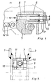
- Fig. 3
- die Vorrichichtung nach Fig. 2 in Rückansicht,
- Fig. 4
- ein Detail der Aufnahme- und Befestigungsvorrichtung in Seitenansicht und
- Fig. 5
- ein Detail der Aufnahme- und Befestigungsvorrichtung in Rückansicht.
- Wie die Figuren 2 und 3 zeigen, hat eine erfindungsgemäße Aufnahme- und Befestigungsvorrichtung 2 im Abstand parallel zueinander stehende Aufnahmelaschen 1 und 2, die einander gegenüberliegende Durchtrittsöffnungen 3 haben. In diese Durchtrittsöffnungen 3 sind in bekannter Weise Verbindungsbolzen einsetzbar, die zugeordnete Ausnehmungen eines nicht dargestellten Baggerarmes durchgreifen, so daß die Aufnahme- und Befestigungsvorrichtung mit dem Baggerarm verbunden ist.
- Wie die Figuren weiter zeigen, hat die Aufnahme- und Befestigungsvorrichtung ein vorderes Aufnahmemaul 4 mit im wesentlichen U-förmigem Querschnitt und ein hinteres Aufnahmemaul 5 mit gleichfalls im wesentlichen U-förmigem Querschnitt, wobei die Öffnungen der beiden Aufnahmemäuler 4 und 5 einander entgegengesetzt gerichtet sind.
- Wie insbesondere die Fig. 4 zeigt, hat das hintere Aufnahmemaul 5 einen Arm 6, der in einer Führung 7 der Aufnahme- und Befestigungsvorrichtung verschiebbar gehalten ist.
- Wie die Fig. 4 weiter zeigt, ist im Arm 6 eine Ausnehmung 8 mit Innengewinde angeordnet, in der eine Spannschraube 9 schraubbar gehalten ist. Die Spannschraube 9 ist drehbar in einer Riegelplatte 10 gehalten, die ihrerseits schwenkbar ist, wie dies der in Fig. 5 mit 11 bezeichnete Doppelpfeil anzeigt.
- Wie insbesondere die Fig. 1 und 2 zeigen, ist das verschiebbare hintere Maul 5 mit der Kolbenstange 12 eines hydraulisch betätigbaren Druckzylinders 13 verbunden.
- Das verschiebbare Maul 5 ist derart mit einer vorgespannten Feder 14 verbunden, daß es durch die Kraft der vorgespannten Feder in Freigabestellung bewegt ist.
- Wie insbesondere die Fig. 1 - 3 zeigen, hat ein Baggerlöffel 15 gleichfalls zwei im Abstand und parallel zueinander verlaufende Aufnahmelaschen 16 mit jeweils zwei einander gegenüberliegenden Durchtrittsöffnungen, in die in bekannter Weise Verbindungsbolzen 17 eingesetzt sind.
- Bei Verwendung der erfindungsgemäßen Aufnahme- und Befestigungsvorrichtung wird die Spannschraube 9 gelöst und die Riegelplatte 10 nach links geschwenkt, in der sie zwischen den Führungen 7 gleiten kann, wie dies in Fig. 5 dargestellt ist. Durch die vorgespannte Feder 14 wird das verschiebbare Aufnahmemaul 5 in Richtung auf das vordere Aufnahmemaul 4 in Freigabestellung bewegt. Anschließend wird die Aufnahmevorrichtung mit dem vorderen Aufnahmemaul 4 in den vorderen Verbindungsbolzens 17 des Baggerlöffels 15 eingehängt, wie dies in Fig. 1 dargestellt ist.
- Nunmehr wird durch die entsprechende Betätigung des nicht dargestellten Auslegerarms durch den Bediener die Aufnahme- und Befestigungsvorrichtung nach unten auf den Baggerlöffel 15 geschwenkt und der Druckzylinder 13 betätigt, so daß das hintere Aufnahmemaul 5 in Schließstellung bewegt wird, in der es in den hinteren Verbindungsbolzen 17 des Baggerlöffels 15 eingreift, wie dies die Fig. 2 zeigt.
- Zur Sicherung der Verbindung wird die Riegelplatte 10 nach rechts um 90° in die in Fig. 4 und 5 gezeigte Stellung geschwenkt, in der sie auf den Führungen 7 aufliegt. Durch Anziehen der Spannschraube 9 wird so eine sichere Verbindung gewährleistet.
- Findet die Aufnahme- und Befestigungsvorrichtung aus Kostengründen Verwendung ohne hydraulisch betätigbaren Druckzylinder, so ist die Riegelplatte 10 in der in Fig. 4 und 5 dargestellten Stellung fest mit den Führungen 7 verbunden, so daß eine Betätigung des verschiebbaren Aufnahmemaules 5 lediglich mit Hilfe der Spannschraube 9 erfolgen kann.
- Durch das verschiebbare Aufnahmemaul 5 ist die Aufnahme- und Befestigungsvorrichtung auch bei Werkzeugen mit unterschiedlichem Abstand der Verbindungsbolzen 17 einsetzbar.
- Wie die Figuren zeigen, sind die Aufnahmemäuler 4, 5 sich zu ihrer öffnung hin keilförmig verbreiternd ausgebildet. Dadurch wird bei Aufnahme eines Werkzeuges ein sicherer, spielfreier Sitz gewährleistet, da sich die Aufnahmebolzen in den Aufnahmemäulern verklemmen.
- Insbesondere die Fig. 2 zeigt weiter, daß das Aufnahmemaul 5 in einem Winkel von ca. 15° zur Verbindungslinie der Aufnahmemäuler 4 und 5 nach unten geneigt verschiebbar in der Aufnahme- und Befestigungsvorrichtung angeordnet ist. Durch diese winkelförmige Anordnung kann der Hydraulikzylinder weiter oberhalb in der Aufnahme- und Befestigungsvorrichtung angeordnet sein, so daß zwischen den Aufnahmemäulern ein Freiraum entsteht. Dies ermöglicht die Aufnahme auch von Werkzeugen, die zwischen den Aufnahmebolzen Höcker od.dgl. aufweisen, wie dies die Fig. 2 zeigt.
- Für Bodenarbeitsgeräte wie Bagger od.dgl. sind am Markt einige Schnellwechselvorrichtungen zu erhalten, die das Austauschen eines Bodenbearbeitungswerkzeuges vereinfachen und erleichtern sollen. Allen bekannten Lösungen ist gemeinsam, daß dazu die marktgängigen Werkzeuge, die von vielen verschiedenen Herstellern zu beziehen sind, speziell für die jeweilige Schnellwechselvorrichtung umgebaut werden müssen oder aber die jeweilige Schnellwechselvorrichtung nur für Werkzeuge einsetzbar sind, die speziell für diese Vorrichtungen gebaut wurden.
- Ziel dieser Erfindung ist es diesen erkannten Nachteil zu beseitigen, und eine Schnellwechselvorrichtung zu entwickeln, die eine Schnellwechslung für marktgängige unveränderte Werkzeuge ermöglicht.
- An den üblichen marktgängigen Werkzeugen, stehen in der Regel zwei Gelenkbolzen zwischen zwei Seitenplatten als Anlenkpunkte für eine Schnellwechselvorrichtung zur Verfügung. In der Regel erstreckt sich zwischen den Gelenkbolzen ein Versteifungsblech, das mit seiner höchsten Erhebung über die direkte Verbindungslinie der Gelenkbolzenmittelpunkte hinausragt. Die Gelenkbolzen-Durchmesser und Positionen können bei den üblichen auf dem Markt erhältlichen Werkzeugen in weiten Bereichen schwanken, und unterliegen auch bei gleichen Baumustern nicht unerheblichen Schwankungen.
- Erfindungsgemäß werden diese Randbedingungen durch geschickte Ausführung und Anordnung der Bauteile der Schnellwechselvorrichtung berücksichtigt, und führen zu einer Lösung, die erstaunlicher Weise für eine sehr große Zahl von marktgängigen Werkzeugen einsetzbar ist. Durch die Ausbildung des Mauls können keilförmige, verschiedene Bolzen-Durchmesser gegriffen werden, wobei die Bolzen nicht an die Rückwand des Maules anschlagen um einen Nachstelleffekt bei Bolzenabnutzung zu erreichen. Die besondere Ausführungsform des Maules bewirkt, daß der im Betrieb von Bodenbearbeitungswerkzeugen anfallende Schmutz beim Einschieben der Schnellwechselvorrichtung auf den Bolzen in die Ecken des Maules ausweichen kann und eine Fehlkupplung durch Schmutzeinwirkung verhindert wird.
- Das bewegliche Maul, das auf den zweiten Gelenkbolzen wirkt, ist erfindungsgemäß so ausgeführt, daß die Betätigungsmittel, Hydraulikzylinder mit Rückstellfeder und Spannschraube in einem Winkel von ca. 15° so geneigt sind, daß die üblichen Verstärkungsbleche auf den Werkzeugen zwischen den Gelenkbolzen beim Kuppeln kein Hinderniss darstellen.
- Das Gewinde der Spannschraube ist durch einen Wellendichtring gegen äußere Einflüsse geschützt. Um einen günstigen Kraftfluß zu erreichen, ist das bewegliche Maul keilförmig gestaltet und klemmt den Gelenkbolzen zwischen Keil und Gehäuse ein. Die Ausrichtung der Betätigungsmittel wurde erfindungsgemäß so gewählt, daß die Betätigungskraft-Richtung in Richtung auf den Bolzenmittelpunkt wirkt und trotzdem der Führungsarm zusammen mit dem Keil aus einem Einzelteil besteht.
- Die erfindungsgemäße Kombination von fernbedienbarem Stellelement (z.B. Hydraulikzylinder) und Spannschraube führt zu folgenden Vorteilen: Bei Ausfall des fernbedienten Stellelementes bleibt das Werkzeug sicher verriegelt. Zusätzlich bleibt die Schnellwechselvorrichtung weiterhin funktionsfähig, d.h. erfindungsgemäß können Werkzeuge bei dieser Anordnung weiterhin von der Vorrichtung gelöst und auch wieder angekuppelt werden. Dabei ist die Vorspannfeder geschickterweise so angeordnet, daß zum einen die Spannschraube beim Öffnen der Verriegelung nicht auf Knicken beansprucht wird, und daß zum anderen, das Verriegeln des Werkzeuges von dem fernbedienbaren Stellelement unterstützt wird, nicht von der Feder, da beim Verriegeln durch ungenaues Positionieren es notwendig ist, das vorpositionierte Werkzeug in Position zu ziehen. Die sich bei der beschriebenen Kombination von fernbedienbarem Stellelement mit Spannschraube ergebene Schwierigkeit, daß ein Bediener die Spannschraube um große Wege verstellen muß, gleichbedeutend mit vielen Umdrehungen an der Spannschraube, bevor das fernbedienbare Stellemement (z.B. Hydraulkizylinder) einsetzen kann, ist erfindungsgemäß dadurch gelöst, daß eine Riegelplatte schwenkbar so angeordnet ist, daß man die Spannschraube im Handumdrehen in- und außer Eingriff bringen kann, um dann z.B. hydraulisch zu verstellen.
- Eine Tellerfeder zwischen Spannschraubenkopf und Riegelplatte dient zusätzlich erfindungsgemäß dazu, die Spannschraube unter Vorspannung zu halten, um ein Lösen der Schraube zu verhindern und zusätzlich dient der von außen sichtbare Federweg der Tellerfeder als optische Kontrolle für den Bediener, der die Schraube dann richtig vorgespannt hat, wenn gerade der volle Federweg der Tellerfeder ausgenutzt wurde.
Claims (8)
- Am Auslegerarm eines Bodenbearbeitungswerkzeuges, Baggers od. dgl. befestigbare Aufnahme- und Befestigungsvorrichtung für ein Werkzeug, einen Baggerlöffel od. dgl., wobei das Werkzeug zwei im Abstand und parallel zueinander stehende Aufnahmelaschen mit jeweils zwei einander gegenüberliegenden Durchtrittsöffnungen hat, in die zur Verbindung des Werkzeuges mit dem Auslegerarm Verbindungsbolzen in zugeordnete Ausnehmungen des Auslegerarmes einsetzbar sind, und wobei die Aufnahme- und Befestigungsvorrichtung gleichfalls zwei im Abstand und parallel zueinander stehende Aufnahmelaschen (1, 2) mit jeweils zwei einander gegenüberliegenden Durchtrittsöffnungen (3), in die zur Verbindung der Aufnahme- und Befestigungsvorrichtung mit dem Auslegerarm Verbindungsbolzen in die zugeordneten Ausnehmungen des Auslegerarmes einsetzbar sind, und zwei im Querschnitt im wesentlichen U-förmige Aufnahmemäuler (4, 5) für die in die Aufnahmelaschen (16) des Werkzeuges (15) eingesetzte Verbindungsbolzen (17) hat, wobei die Aufnahmemäuler mit ihrer Öffnung einander entgegengesetzt in der Aufnahme- und Befestigungsvorrichtung angeordnet sind und ein Aufnahmemaul (5) mit einem Arm in Richtung auf das andere Aufnahmemaul (4) verschiebbar und festlegbar in Führungen (7) der Aufnahme und Befestigungsvorrichtung angeordnet ist, dadurch gekennzeichnet, daß in einer Ausnehmung (8) mit Innengewinde des Armes (6) des verschiebbaren Aufnahmemauls (5) eine Spannschraube (9) schraubbar eingesetzt ist, die drehbar in einer Gegendruckplatte (10) der Aufnahme- und Befestigungsvorrichtung gehalten ist.
- Aufnahme- und Befestigungsvorrichtung nach Anspruch 1, dadurch gekennzeichnet, daß die Gegendruckplatte (10) fest in der Aufnahme- und Befestigungsvorrichtung angeordnet ist.
- Aufnahme- und Befestigungsvorrichtung nach einem der Ansprüche 1 bzw. 2, dadurch gekennzeichnet, daß die Gegendruckplatte (10) als in Freigabestellung schwenkbare Riegelplatte ausgebildet ist.
- Aufnahme- und Befestigungsvorrichtung nach einem der Ansprüche 1 - 3, dadurch gekennzeichnet, daß das verschiebbare Aufnahmemaul (5) mit der Kolbenstange (12) eines in der Aufnahme- und Befestigungsvorrichtung angeordneten hydraulisch betätigbaren Druckzylinders (13) verbunden ist.
- Aufnahme- und Befestigungsvorrichtung nach Anspruch 4, dadurch gekennzeichnet, daß das verschiebbare Aufnahmemaul (5) derart mit einer vorgespannten Feder (14) verbunden ist, daß das Aufnahmemaul durch die Kraft der vorgespannten Feder in Freigabestellung bewegt ist.
- Aufnahme- und Befestigungsvorrichtung nach einem der Ansprüche 1 -5, dadurch gekennzeichnet, daß die Aufnahmemäuler (4, 5) sich zu ihrer öffnung hin keilförmig verbreiternd ausgebildet sind.
- Aufnahme- und Befestigungsvorrichtung nach einem der Ansprüche 1 - 5, dadurch gekennzeichnet, daß das Aufnahmemaul (5) in einem Winkel zur Verbindungslinie der Aufnahmemäuler (4, 5) nach unten geneigt verschiebbar in der Aufnahme- und Befestigungsvorrichtung angeordnet ist.
- Aufnahme- und Befestigungsvorrichtung nach Anspruch 7, dadurch gekennzeichnet, daß der Winkel zwischen der Verbindungslinie der Aufnahmemäuler (4, 5) und der Verschieberichtung des Aufnahmemauls (5) ca. 15° beträgt.
Priority Applications (1)
| Application Number | Priority Date | Filing Date | Title |
|---|---|---|---|
| SI9530378T SI0674053T1 (en) | 1994-03-24 | 1995-03-23 | Quick-action coupling for excavator attachment |
Applications Claiming Priority (2)
| Application Number | Priority Date | Filing Date | Title |
|---|---|---|---|
| DE4410194A DE4410194A1 (de) | 1994-03-24 | 1994-03-24 | Am Auslegerarm eines Bodenbearbeitungswerkzeuges, Baggers o. dgl. befestigbare Aufnahme- und Befestigungsvorrichtung für ein Werkzeug, einen Baggerlöffel o. dgl. |
| DE4410194 | 1994-03-24 |
Publications (3)
| Publication Number | Publication Date |
|---|---|
| EP0674053A2 true EP0674053A2 (de) | 1995-09-27 |
| EP0674053A3 EP0674053A3 (de) | 1996-04-24 |
| EP0674053B1 EP0674053B1 (de) | 1999-12-01 |
Family
ID=6513725
Family Applications (1)
| Application Number | Title | Priority Date | Filing Date |
|---|---|---|---|
| EP95104275A Expired - Lifetime EP0674053B1 (de) | 1994-03-24 | 1995-03-23 | Schnellkupplung eines Arbeitsvorsatzes an Baggern |
Country Status (8)
| Country | Link |
|---|---|
| EP (1) | EP0674053B1 (de) |
| AT (1) | ATE187220T1 (de) |
| DE (2) | DE4410194A1 (de) |
| DK (1) | DK0674053T3 (de) |
| ES (1) | ES2139767T3 (de) |
| GR (1) | GR3032345T3 (de) |
| PT (1) | PT674053E (de) |
| SI (1) | SI0674053T1 (de) |
Cited By (6)
| Publication number | Priority date | Publication date | Assignee | Title |
|---|---|---|---|---|
| DE19507896A1 (de) * | 1995-03-07 | 1995-10-26 | Frank Von Wolff | Schnellwechselvorrichtung |
| WO1997028314A1 (de) * | 1996-02-02 | 1997-08-07 | Nagler Juergen | Werkzeugwechselvorrichtung für hydraulikbagger |
| WO1998046835A1 (de) * | 1997-04-14 | 1998-10-22 | Baumaschinentechnik Gesellschaft Mbh | Schnellwechselvorrichtung für bagger |
| DE102010006692A1 (de) | 2010-02-02 | 2011-08-04 | Meyer, Runald, 55496 | Mechanischer Hydraulik-Schnellverbinder |
| DE202013002103U1 (de) | 2013-03-06 | 2013-04-11 | Marc Patrick Meyer | Vorrichtung zur Verbindung von Bauteilen zum gleichzeitigen Übertragen von Kraft und Medium |
| US11846083B2 (en) | 2015-12-07 | 2023-12-19 | Wedgelock Equipment Limited | Locking device for a quick coupler |
Families Citing this family (6)
| Publication number | Priority date | Publication date | Assignee | Title |
|---|---|---|---|---|
| AT403490B (de) * | 1996-01-15 | 1998-02-25 | Franz Winkelbauer | Kupplungseinrichtung |
| AT409323B (de) * | 2000-12-15 | 2002-07-25 | Auer Landmaschb Ges M B H | Vorrichtung zum holzrücken |
| US20100000129A1 (en) * | 2005-11-15 | 2010-01-07 | Timothy Craig Balemi | Bucket Fabrication |
| DE102015225498A1 (de) | 2015-12-16 | 2017-06-22 | Oilquick Deutschland Gmbh | Schnellwechselsystem mit mechanischer sicherheitseinrichtung gegen unbeabsichtigtes ablösen eines arbeitsgerätes |
| CN107130657A (zh) * | 2017-04-30 | 2017-09-05 | 经海波 | 一种挖掘机快速接头 |
| US11208785B2 (en) | 2018-12-12 | 2021-12-28 | Caterpillar Inc. | Tool coupling arrangement having zero offset |
Citations (5)
| Publication number | Priority date | Publication date | Assignee | Title |
|---|---|---|---|---|
| WO1988002421A1 (en) | 1986-10-03 | 1988-04-07 | Stuart Alexander Essex | Excavator attachment |
| EP0468771A1 (de) | 1990-07-25 | 1992-01-29 | Japanic Corporation | Werkzeugkupplungsvorrichtung einer Erdbaumaschine |
| FR2670520A1 (fr) | 1990-12-17 | 1992-06-19 | Esco Sa | Dispositif perfectionne de fixation, rapide d'outil de travail sur un bras d'une machine notamment de travaux publics. |
| EP0521560A2 (de) | 1991-07-02 | 1993-01-07 | Methold 's-Hertogenbosch B.V. | Verbindungsstück |
| WO1993005241A1 (en) | 1991-09-06 | 1993-03-18 | John Teodor Sonerud | A device for quick connection of hydraulic tubings |
Family Cites Families (3)
| Publication number | Priority date | Publication date | Assignee | Title |
|---|---|---|---|---|
| FR2494001A1 (fr) * | 1980-11-13 | 1982-05-14 | Kodak Pathe | Emballage pour pile de feuilles notamment films photosensibles |
| WO1988001322A1 (en) * | 1986-08-18 | 1988-02-25 | Paul Owen Jones | Improved hitch |
| DE9405014U1 (de) * | 1994-03-24 | 1994-05-26 | Leh, Karl Heinz Josef, 55765 Birkenfeld | Am Auslegerarm eines Bodenbearbeitungswerkzeuges, Baggers o. dgl. befestigbare Aufnahme- und Befestigungsvorrichtung für ein Werkzeug, einen Baggerlöffel o. dgl. |
-
1994
- 1994-03-24 DE DE4410194A patent/DE4410194A1/de not_active Ceased
-
1995
- 1995-03-23 EP EP95104275A patent/EP0674053B1/de not_active Expired - Lifetime
- 1995-03-23 DE DE59507299T patent/DE59507299D1/de not_active Expired - Lifetime
- 1995-03-23 PT PT674053T patent/PT674053E/pt unknown
- 1995-03-23 SI SI9530378T patent/SI0674053T1/xx unknown
- 1995-03-23 AT AT95104275T patent/ATE187220T1/de active
- 1995-03-23 ES ES95104275T patent/ES2139767T3/es not_active Expired - Lifetime
- 1995-03-23 DK DK95104275T patent/DK0674053T3/da active
-
2000
- 2000-01-13 GR GR20000400041T patent/GR3032345T3/el not_active IP Right Cessation
Patent Citations (5)
| Publication number | Priority date | Publication date | Assignee | Title |
|---|---|---|---|---|
| WO1988002421A1 (en) | 1986-10-03 | 1988-04-07 | Stuart Alexander Essex | Excavator attachment |
| EP0468771A1 (de) | 1990-07-25 | 1992-01-29 | Japanic Corporation | Werkzeugkupplungsvorrichtung einer Erdbaumaschine |
| FR2670520A1 (fr) | 1990-12-17 | 1992-06-19 | Esco Sa | Dispositif perfectionne de fixation, rapide d'outil de travail sur un bras d'une machine notamment de travaux publics. |
| EP0521560A2 (de) | 1991-07-02 | 1993-01-07 | Methold 's-Hertogenbosch B.V. | Verbindungsstück |
| WO1993005241A1 (en) | 1991-09-06 | 1993-03-18 | John Teodor Sonerud | A device for quick connection of hydraulic tubings |
Cited By (7)
| Publication number | Priority date | Publication date | Assignee | Title |
|---|---|---|---|---|
| DE19507896A1 (de) * | 1995-03-07 | 1995-10-26 | Frank Von Wolff | Schnellwechselvorrichtung |
| WO1997028314A1 (de) * | 1996-02-02 | 1997-08-07 | Nagler Juergen | Werkzeugwechselvorrichtung für hydraulikbagger |
| WO1998046835A1 (de) * | 1997-04-14 | 1998-10-22 | Baumaschinentechnik Gesellschaft Mbh | Schnellwechselvorrichtung für bagger |
| DE102010006692A1 (de) | 2010-02-02 | 2011-08-04 | Meyer, Runald, 55496 | Mechanischer Hydraulik-Schnellverbinder |
| DE202013002103U1 (de) | 2013-03-06 | 2013-04-11 | Marc Patrick Meyer | Vorrichtung zur Verbindung von Bauteilen zum gleichzeitigen Übertragen von Kraft und Medium |
| US11846083B2 (en) | 2015-12-07 | 2023-12-19 | Wedgelock Equipment Limited | Locking device for a quick coupler |
| US12428799B2 (en) | 2015-12-07 | 2025-09-30 | Wedgelock Equipment Limited | Locking device for a quick coupler |
Also Published As
| Publication number | Publication date |
|---|---|
| EP0674053B1 (de) | 1999-12-01 |
| SI0674053T1 (en) | 2000-06-30 |
| ES2139767T3 (es) | 2000-02-16 |
| EP0674053A3 (de) | 1996-04-24 |
| DE59507299D1 (de) | 2000-01-05 |
| DE4410194A1 (de) | 1995-10-05 |
| ATE187220T1 (de) | 1999-12-15 |
| GR3032345T3 (en) | 2000-04-27 |
| DK0674053T3 (da) | 2000-05-29 |
| PT674053E (pt) | 2000-04-28 |
Similar Documents
| Publication | Publication Date | Title |
|---|---|---|
| DE60219774T2 (de) | Ventilsperrvorrichtung | |
| EP0674053A2 (de) | Schnellkupplung eines Arbeitsvorsatzes an Baggern | |
| EP1325196B1 (de) | Anordnung zum auswechselbaren befestigen eines anbauteiles, z.b. einer baggerschaufel, an einem baggerausleger oder einem fahrzeug | |
| DE2258357A1 (de) | Grabemaschine | |
| DE4317564C2 (de) | Türöffner mit einer verriegelbaren, schwenkbaren Falle | |
| DE102020105460A1 (de) | Schnellwechsler | |
| EP0754829B1 (de) | Vorrichtung zum Anschliessen eines Schwenkteils, beispielsweise einer Fahrzeughaube an einen Körper, beispielsweise an einen Fahrzeugrahmen | |
| DE202021101016U1 (de) | Schnellwechsler für Baumaschinenwerkzeuge | |
| DE9405014U1 (de) | Am Auslegerarm eines Bodenbearbeitungswerkzeuges, Baggers o. dgl. befestigbare Aufnahme- und Befestigungsvorrichtung für ein Werkzeug, einen Baggerlöffel o. dgl. | |
| DE3133263C2 (de) | Bohrgestängeführung | |
| EP1651818A1 (de) | Anordnung zum auswechselbaren befestigen eines anbauteiles, z.b. einer baggerschaufel, an einem baggerausleger oder einem fahrzeug | |
| DE2721107A1 (de) | Vorrichtung zur verbindung eines arbeitswerkzeuges an einem tragarm, insbesondere an einem holm | |
| AT411839B (de) | Frontlader | |
| DE102019125861A1 (de) | Schnellwechsler | |
| DE19806057A1 (de) | Baumaschinenadapter | |
| WO2002088477A1 (de) | Frontlader | |
| DE29601727U1 (de) | Werkzeugwechselvorrichtung für Hydraulikbagger | |
| EP0096209A2 (de) | Vorrichtung zum Trennen von Flüssigkeitsleitungsenden | |
| EP0625613B1 (de) | Vorrichtung zum auswechselbaren Befestigen eines werkzeugartigen Anbauteils am vorderen Ende eines Baggerstiels eines Baggers | |
| EP0392972B1 (de) | Kupplung für Baggerlöffel | |
| EP0758552B1 (de) | Befestigung eines Werkzeuges an der Ladeschwinge einer fahrbaren Arbeitsmaschine | |
| DE29810751U1 (de) | Arbeitswerkzeug, insbesondere Greifer, für ein Arbeitsgerät wie einen Bagger | |
| DE10332409B4 (de) | Diebstahlsicherung für eine Zugkugelkupplung | |
| EP0758575A1 (de) | Spannvorrichtungs-Wechselbausatz | |
| EP4711525A1 (de) | Schnellwechselvorrichtung |
Legal Events
| Date | Code | Title | Description |
|---|---|---|---|
| PUAI | Public reference made under article 153(3) epc to a published international application that has entered the european phase |
Free format text: ORIGINAL CODE: 0009012 |
|
| AK | Designated contracting states |
Kind code of ref document: A2 Designated state(s): AT BE CH DE DK ES FR GB GR IE IT LI LU MC NL PT SE |
|
| RAX | Requested extension states of the european patent have changed |
Free format text: SI PAYMENT 950404 |
|
| PUAL | Search report despatched |
Free format text: ORIGINAL CODE: 0009013 |
|
| AK | Designated contracting states |
Kind code of ref document: A3 Designated state(s): AT BE CH DE DK ES FR GB GR IE IT LI LU MC NL PT SE |
|
| AX | Request for extension of the european patent |
Free format text: SI PAYMENT 950404 |
|
| 17P | Request for examination filed |
Effective date: 19960621 |
|
| TPAD | Observations filed by third parties |
Free format text: ORIGINAL CODE: EPIDOS TIPA |
|
| 17Q | First examination report despatched |
Effective date: 19980520 |
|
| GRAG | Despatch of communication of intention to grant |
Free format text: ORIGINAL CODE: EPIDOS AGRA |
|
| GRAG | Despatch of communication of intention to grant |
Free format text: ORIGINAL CODE: EPIDOS AGRA |
|
| GRAH | Despatch of communication of intention to grant a patent |
Free format text: ORIGINAL CODE: EPIDOS IGRA |
|
| GRAH | Despatch of communication of intention to grant a patent |
Free format text: ORIGINAL CODE: EPIDOS IGRA |
|
| GRAA | (expected) grant |
Free format text: ORIGINAL CODE: 0009210 |
|
| AK | Designated contracting states |
Kind code of ref document: B1 Designated state(s): AT BE CH DE DK ES FR GB GR IE IT LI LU MC NL PT SE |
|
| AX | Request for extension of the european patent |
Free format text: SI PAYMENT 19950404 |
|
| REF | Corresponds to: |
Ref document number: 187220 Country of ref document: AT Date of ref document: 19991215 Kind code of ref document: T |
|
| REG | Reference to a national code |
Ref country code: CH Ref legal event code: EP |
|
| REF | Corresponds to: |
Ref document number: 59507299 Country of ref document: DE Date of ref document: 20000105 |
|
| ITF | It: translation for a ep patent filed | ||
| REG | Reference to a national code |
Ref country code: IE Ref legal event code: FG4D Free format text: GERMAN |
|
| REG | Reference to a national code |
Ref country code: ES Ref legal event code: FG2A Ref document number: 2139767 Country of ref document: ES Kind code of ref document: T3 |
|
| ET | Fr: translation filed | ||
| GBT | Gb: translation of ep patent filed (gb section 77(6)(a)/1977) |
Effective date: 20000210 |
|
| REG | Reference to a national code |
Ref country code: PT Ref legal event code: SC4A Free format text: AVAILABILITY OF NATIONAL TRANSLATION Effective date: 20000114 |
|
| REG | Reference to a national code |
Ref country code: DK Ref legal event code: T3 |
|
| PLBE | No opposition filed within time limit |
Free format text: ORIGINAL CODE: 0009261 |
|
| STAA | Information on the status of an ep patent application or granted ep patent |
Free format text: STATUS: NO OPPOSITION FILED WITHIN TIME LIMIT |
|
| 26N | No opposition filed | ||
| REG | Reference to a national code |
Ref country code: GB Ref legal event code: IF02 |
|
| REG | Reference to a national code |
Ref country code: SI Ref legal event code: IF |
|
| PGFP | Annual fee paid to national office [announced via postgrant information from national office to epo] |
Ref country code: GB Payment date: 20070314 Year of fee payment: 13 |
|
| PGFP | Annual fee paid to national office [announced via postgrant information from national office to epo] |
Ref country code: DK Payment date: 20070315 Year of fee payment: 13 |
|
| PGFP | Annual fee paid to national office [announced via postgrant information from national office to epo] |
Ref country code: SE Payment date: 20070326 Year of fee payment: 13 |
|
| PGFP | Annual fee paid to national office [announced via postgrant information from national office to epo] |
Ref country code: IE Payment date: 20070330 Year of fee payment: 13 |
|
| PGFP | Annual fee paid to national office [announced via postgrant information from national office to epo] |
Ref country code: MC Payment date: 20070427 Year of fee payment: 13 |
|
| PG25 | Lapsed in a contracting state [announced via postgrant information from national office to epo] |
Ref country code: MC Free format text: LAPSE BECAUSE OF NON-PAYMENT OF DUE FEES Effective date: 20080331 |
|
| REG | Reference to a national code |
Ref country code: DK Ref legal event code: EBP |
|
| EUG | Se: european patent has lapsed | ||
| GBPC | Gb: european patent ceased through non-payment of renewal fee |
Effective date: 20080323 |
|
| REG | Reference to a national code |
Ref country code: IE Ref legal event code: MM4A |
|
| PG25 | Lapsed in a contracting state [announced via postgrant information from national office to epo] |
Ref country code: SE Free format text: LAPSE BECAUSE OF NON-PAYMENT OF DUE FEES Effective date: 20080324 Ref country code: IE Free format text: LAPSE BECAUSE OF NON-PAYMENT OF DUE FEES Effective date: 20080324 |
|
| PG25 | Lapsed in a contracting state [announced via postgrant information from national office to epo] |
Ref country code: DK Free format text: LAPSE BECAUSE OF NON-PAYMENT OF DUE FEES Effective date: 20080331 |
|
| PGFP | Annual fee paid to national office [announced via postgrant information from national office to epo] |
Ref country code: PT Payment date: 20090303 Year of fee payment: 15 Ref country code: NL Payment date: 20090303 Year of fee payment: 15 |
|
| PG25 | Lapsed in a contracting state [announced via postgrant information from national office to epo] |
Ref country code: GB Free format text: LAPSE BECAUSE OF NON-PAYMENT OF DUE FEES Effective date: 20080323 |
|
| PGFP | Annual fee paid to national office [announced via postgrant information from national office to epo] |
Ref country code: GR Payment date: 20090330 Year of fee payment: 15 |
|
| PGFP | Annual fee paid to national office [announced via postgrant information from national office to epo] |
Ref country code: IT Payment date: 20090326 Year of fee payment: 15 |
|
| REG | Reference to a national code |
Ref country code: NL Ref legal event code: V1 Effective date: 20101001 |
|
| REG | Reference to a national code |
Ref country code: SI Ref legal event code: KO00 Effective date: 20101102 |
|
| PG25 | Lapsed in a contracting state [announced via postgrant information from national office to epo] |
Ref country code: PT Free format text: LAPSE BECAUSE OF NON-PAYMENT OF DUE FEES Effective date: 20100923 Ref country code: NL Free format text: LAPSE BECAUSE OF NON-PAYMENT OF DUE FEES Effective date: 20101001 |
|
| PG25 | Lapsed in a contracting state [announced via postgrant information from national office to epo] |
Ref country code: GR Free format text: LAPSE BECAUSE OF NON-PAYMENT OF DUE FEES Effective date: 20101004 Ref country code: IT Free format text: LAPSE BECAUSE OF NON-PAYMENT OF DUE FEES Effective date: 20100323 |
|
| PGFP | Annual fee paid to national office [announced via postgrant information from national office to epo] |
Ref country code: FR Payment date: 20130408 Year of fee payment: 19 Ref country code: ES Payment date: 20130321 Year of fee payment: 19 Ref country code: LU Payment date: 20130318 Year of fee payment: 19 Ref country code: CH Payment date: 20130314 Year of fee payment: 19 |
|
| PGFP | Annual fee paid to national office [announced via postgrant information from national office to epo] |
Ref country code: BE Payment date: 20130228 Year of fee payment: 19 |
|
| PGFP | Annual fee paid to national office [announced via postgrant information from national office to epo] |
Ref country code: AT Payment date: 20130314 Year of fee payment: 19 |
|
| PG25 | Lapsed in a contracting state [announced via postgrant information from national office to epo] |
Ref country code: LU Free format text: LAPSE BECAUSE OF NON-PAYMENT OF DUE FEES Effective date: 20140323 |
|
| PGFP | Annual fee paid to national office [announced via postgrant information from national office to epo] |
Ref country code: DE Payment date: 20140729 Year of fee payment: 20 |
|
| REG | Reference to a national code |
Ref country code: CH Ref legal event code: PL |
|
| REG | Reference to a national code |
Ref country code: AT Ref legal event code: MM01 Ref document number: 187220 Country of ref document: AT Kind code of ref document: T Effective date: 20140323 |
|
| REG | Reference to a national code |
Ref country code: FR Ref legal event code: ST Effective date: 20141128 |
|
| PG25 | Lapsed in a contracting state [announced via postgrant information from national office to epo] |
Ref country code: FR Free format text: LAPSE BECAUSE OF NON-PAYMENT OF DUE FEES Effective date: 20140331 Ref country code: LI Free format text: LAPSE BECAUSE OF NON-PAYMENT OF DUE FEES Effective date: 20140331 Ref country code: CH Free format text: LAPSE BECAUSE OF NON-PAYMENT OF DUE FEES Effective date: 20140331 |
|
| PG25 | Lapsed in a contracting state [announced via postgrant information from national office to epo] |
Ref country code: AT Free format text: LAPSE BECAUSE OF NON-PAYMENT OF DUE FEES Effective date: 20140323 |
|
| REG | Reference to a national code |
Ref country code: DE Ref legal event code: R071 Ref document number: 59507299 Country of ref document: DE |
|
| REG | Reference to a national code |
Ref country code: ES Ref legal event code: FD2A Effective date: 20150424 |
|
| PG25 | Lapsed in a contracting state [announced via postgrant information from national office to epo] |
Ref country code: ES Free format text: LAPSE BECAUSE OF NON-PAYMENT OF DUE FEES Effective date: 20140324 |
|
| PG25 | Lapsed in a contracting state [announced via postgrant information from national office to epo] |
Ref country code: BE Free format text: LAPSE BECAUSE OF NON-PAYMENT OF DUE FEES Effective date: 20140331 |