EP0673729B1 - Dispositif pour la coupe de produits imprimés - Google Patents
Dispositif pour la coupe de produits imprimés Download PDFInfo
- Publication number
- EP0673729B1 EP0673729B1 EP95810155A EP95810155A EP0673729B1 EP 0673729 B1 EP0673729 B1 EP 0673729B1 EP 95810155 A EP95810155 A EP 95810155A EP 95810155 A EP95810155 A EP 95810155A EP 0673729 B1 EP0673729 B1 EP 0673729B1
- Authority
- EP
- European Patent Office
- Prior art keywords
- printed products
- trimming
- supporting device
- knife
- cutting
- Prior art date
- Legal status (The legal status is an assumption and is not a legal conclusion. Google has not performed a legal analysis and makes no representation as to the accuracy of the status listed.)
- Expired - Lifetime
Links
Images
Classifications
-
- B—PERFORMING OPERATIONS; TRANSPORTING
- B26—HAND CUTTING TOOLS; CUTTING; SEVERING
- B26D—CUTTING; DETAILS COMMON TO MACHINES FOR PERFORATING, PUNCHING, CUTTING-OUT, STAMPING-OUT OR SEVERING
- B26D7/00—Details of apparatus for cutting, cutting-out, stamping-out, punching, perforating, or severing by means other than cutting
- B26D7/06—Arrangements for feeding or delivering work of other than sheet, web, or filamentary form
- B26D7/0675—Arrangements for feeding or delivering work of other than sheet, web, or filamentary form specially adapted for piles of sheets
-
- B—PERFORMING OPERATIONS; TRANSPORTING
- B26—HAND CUTTING TOOLS; CUTTING; SEVERING
- B26D—CUTTING; DETAILS COMMON TO MACHINES FOR PERFORATING, PUNCHING, CUTTING-OUT, STAMPING-OUT OR SEVERING
- B26D1/00—Cutting through work characterised by the nature or movement of the cutting member or particular materials not otherwise provided for; Apparatus or machines therefor; Cutting members therefor
- B26D1/01—Cutting through work characterised by the nature or movement of the cutting member or particular materials not otherwise provided for; Apparatus or machines therefor; Cutting members therefor involving a cutting member which does not travel with the work
- B26D1/12—Cutting through work characterised by the nature or movement of the cutting member or particular materials not otherwise provided for; Apparatus or machines therefor; Cutting members therefor involving a cutting member which does not travel with the work having a cutting member moving about an axis
- B26D1/25—Cutting through work characterised by the nature or movement of the cutting member or particular materials not otherwise provided for; Apparatus or machines therefor; Cutting members therefor involving a cutting member which does not travel with the work having a cutting member moving about an axis with a non-circular cutting member
- B26D1/34—Cutting through work characterised by the nature or movement of the cutting member or particular materials not otherwise provided for; Apparatus or machines therefor; Cutting members therefor involving a cutting member which does not travel with the work having a cutting member moving about an axis with a non-circular cutting member moving about an axis parallel to the line of cut
- B26D1/38—Cutting through work characterised by the nature or movement of the cutting member or particular materials not otherwise provided for; Apparatus or machines therefor; Cutting members therefor involving a cutting member which does not travel with the work having a cutting member moving about an axis with a non-circular cutting member moving about an axis parallel to the line of cut and coacting with a fixed blade or other fixed member
-
- B—PERFORMING OPERATIONS; TRANSPORTING
- B26—HAND CUTTING TOOLS; CUTTING; SEVERING
- B26D—CUTTING; DETAILS COMMON TO MACHINES FOR PERFORATING, PUNCHING, CUTTING-OUT, STAMPING-OUT OR SEVERING
- B26D1/00—Cutting through work characterised by the nature or movement of the cutting member or particular materials not otherwise provided for; Apparatus or machines therefor; Cutting members therefor
- B26D1/56—Cutting through work characterised by the nature or movement of the cutting member or particular materials not otherwise provided for; Apparatus or machines therefor; Cutting members therefor involving a cutting member which travels with the work otherwise than in the direction of the cut, i.e. flying cutter
- B26D1/62—Cutting through work characterised by the nature or movement of the cutting member or particular materials not otherwise provided for; Apparatus or machines therefor; Cutting members therefor involving a cutting member which travels with the work otherwise than in the direction of the cut, i.e. flying cutter and is rotating about an axis parallel to the line of cut, e.g. mounted on a rotary cylinder
-
- B—PERFORMING OPERATIONS; TRANSPORTING
- B26—HAND CUTTING TOOLS; CUTTING; SEVERING
- B26D—CUTTING; DETAILS COMMON TO MACHINES FOR PERFORATING, PUNCHING, CUTTING-OUT, STAMPING-OUT OR SEVERING
- B26D7/00—Details of apparatus for cutting, cutting-out, stamping-out, punching, perforating, or severing by means other than cutting
- B26D7/01—Means for holding or positioning work
- B26D7/02—Means for holding or positioning work with clamping means
- B26D7/025—Means for holding or positioning work with clamping means acting upon planar surfaces
-
- B—PERFORMING OPERATIONS; TRANSPORTING
- B26—HAND CUTTING TOOLS; CUTTING; SEVERING
- B26D—CUTTING; DETAILS COMMON TO MACHINES FOR PERFORATING, PUNCHING, CUTTING-OUT, STAMPING-OUT OR SEVERING
- B26D7/00—Details of apparatus for cutting, cutting-out, stamping-out, punching, perforating, or severing by means other than cutting
- B26D2007/0012—Details, accessories or auxiliary or special operations not otherwise provided for
- B26D2007/0081—Cutting on three sides, e.g. trilateral trimming
-
- Y—GENERAL TAGGING OF NEW TECHNOLOGICAL DEVELOPMENTS; GENERAL TAGGING OF CROSS-SECTIONAL TECHNOLOGIES SPANNING OVER SEVERAL SECTIONS OF THE IPC; TECHNICAL SUBJECTS COVERED BY FORMER USPC CROSS-REFERENCE ART COLLECTIONS [XRACs] AND DIGESTS
- Y10—TECHNICAL SUBJECTS COVERED BY FORMER USPC
- Y10S—TECHNICAL SUBJECTS COVERED BY FORMER USPC CROSS-REFERENCE ART COLLECTIONS [XRACs] AND DIGESTS
- Y10S83/00—Cutting
- Y10S83/929—Particular nature of work or product
- Y10S83/934—Book, being made, e.g. trimming a signature
-
- Y—GENERAL TAGGING OF NEW TECHNOLOGICAL DEVELOPMENTS; GENERAL TAGGING OF CROSS-SECTIONAL TECHNOLOGIES SPANNING OVER SEVERAL SECTIONS OF THE IPC; TECHNICAL SUBJECTS COVERED BY FORMER USPC CROSS-REFERENCE ART COLLECTIONS [XRACs] AND DIGESTS
- Y10—TECHNICAL SUBJECTS COVERED BY FORMER USPC
- Y10T—TECHNICAL SUBJECTS COVERED BY FORMER US CLASSIFICATION
- Y10T83/00—Cutting
- Y10T83/647—With means to convey work relative to tool station
- Y10T83/6476—Including means to move work from one tool station to another
- Y10T83/6483—Tool stations staggered relative to one another
-
- Y—GENERAL TAGGING OF NEW TECHNOLOGICAL DEVELOPMENTS; GENERAL TAGGING OF CROSS-SECTIONAL TECHNOLOGIES SPANNING OVER SEVERAL SECTIONS OF THE IPC; TECHNICAL SUBJECTS COVERED BY FORMER USPC CROSS-REFERENCE ART COLLECTIONS [XRACs] AND DIGESTS
- Y10—TECHNICAL SUBJECTS COVERED BY FORMER USPC
- Y10T—TECHNICAL SUBJECTS COVERED BY FORMER US CLASSIFICATION
- Y10T83/00—Cutting
- Y10T83/647—With means to convey work relative to tool station
- Y10T83/654—With work-constraining means on work conveyor [i.e., "work-carrier"]
- Y10T83/6542—Plural means to constrain plural work pieces
-
- Y—GENERAL TAGGING OF NEW TECHNOLOGICAL DEVELOPMENTS; GENERAL TAGGING OF CROSS-SECTIONAL TECHNOLOGIES SPANNING OVER SEVERAL SECTIONS OF THE IPC; TECHNICAL SUBJECTS COVERED BY FORMER USPC CROSS-REFERENCE ART COLLECTIONS [XRACs] AND DIGESTS
- Y10—TECHNICAL SUBJECTS COVERED BY FORMER USPC
- Y10T—TECHNICAL SUBJECTS COVERED BY FORMER US CLASSIFICATION
- Y10T83/00—Cutting
- Y10T83/647—With means to convey work relative to tool station
- Y10T83/658—With projections on work-carrier [e.g., pin wheel]
Definitions
- the invention relates to a device for trimming at least an edge from one at regular intervals encircling, bag-like conveyor units that can be loaded from above formed conveyor continuously fed Printed products whose edges protrude from the conveyor units one on the side of the conveyor
- Enforce cutting device which consists of at least one Knife formed a cutting device at the back of the Printed products, set back from the protruding edge and opposite the knife during the cutting process, at least can be brought into contact in the same direction over the cutting length and driven in time with the supplied print products, associated with at least one shoulder supporting device is.
- Such a device has become known from CH - A - 668 216.
- Knives which are assigned to one another in pairs are provided as the cutting device, which are joined together at the same intervals as the pocket-like conveying units of the conveying device to endlessly driven traction elements, one strand of which runs parallel to a section of the conveying device formed from tractive elements and is driven in the same direction and at the same speed as this is.
- EP - A - 0 367 715 conveys a method for trimming the side edges of continuously conveyed printed products in a continuous process, with each printed product being assigned a trailing, first knife part which is effective in conveying and which moves or moves the printed product at substantially the same speed. drives and brings into contact with one another along a provided cutting edge, such that the first knife part, which corresponds to the conveying unit of a conveying device, and the printed product belonging to it, are guided past a second stationary knife part in order to be brought into cutting engagement therewith.
- a device which has a conveying device with a plurality of conveying units rotating on a closed path for receiving the continuously occurring printed products, the conveying units on the back of the printed products containing a counter knife and having means for conveying the printed products in the conveying units at least along the intended Bring the cutting edge into contact with the counter knife before they pass through a stationary cutting knife or second knife part, which cooperates with the counter knife or first knife part of each conveyor unit, and are thus trimmed along the formed cutting edge. Due to the sudden cutting forces, such a design requires a high level of design effort in order to be able to achieve a stability with the conveyor units that conveys the necessary cutting quality. It thus turns out to be unfavorable for the cutting process if the conveyor units suspended on traction elements and moved in longitudinal guides with lateral play are exposed to high loads.
- the object of the invention is therefore a device for trimming of printed products according to the aforementioned type to create, in which by a compared to the known Constructions different construction the disadvantages mentioned do not occur or where the required cut quality and the inherent stability required for this in a simple manner Way can be achieved.
- this object is achieved in the device mentioned at the outset in that the support device is designed to be rotatable about an axis arranged parallel to the cutting edge and the knife is fixed concentrically to a support which is rotatable with respect to and within the support device.
- This configuration makes it possible to keep the forces arising from the cutting process away from the conveyor device and to carry out the cutting process in a stable environment.
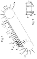
- a device 1 for trimming several edges of printed products 2 which are fed at regular intervals, for example from a rotary printing press or a saddle stitcher.
- the latter are fed in from pocket-type conveyor units 3 of a conveying device 4 which can be loaded from above for transport.
- the conveyor units 3 are designed with endlessly driven traction elements 6 rotating around at least two spaced rollers 5 and possibly adjustable in terms of their absorption capacity or to the size of the load or. of the printed products 2, which are clamped in the conveyor units during the cutting process.
- the course of the run of the conveying device 4 is provided obliquely upwards, so that the printed products 2 occurring in the conveying units 3 can lie flatly stretched against the rear wall of the conveying units 3.
- Retaining elements ensure that the printed products 2 are held on the rear wall of the conveyor units 3 after they have taken up the position for trimming the edges, for example with the aid of guide means.
- two continuously arranged belts 6, which are arranged at a lateral distance from one another and offer a support surface and preferably run at the same speed, are provided below the conveyor units 3 and can also be seen in FIG. 2.
- the lateral guidance of the printed products 2 is carried out in a similar manner by means of preferably adjustable guide belts 7 arranged on the side of the conveying device 4 (see also FIG. 3).
- Static repellants or other known means could also be used for this purpose.
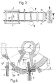
- FIG. 4 illustrates a cutting device 8 belonging to the device 1, as is shown in the arrangement, for example, in FIGS. 1 and 3.
- Reference symbol 9 indicates the cut edges for the head and / or foot side or the open side edge of a printed product 2 to be trimmed.
- the cutting edge 10 which is opposite to the conveying direction of the printed products, of a stationary knife 11, which protrudes beyond the maximum width of the sides of a printed product 2 and is removably attached to a support 12.
- the cutting edge can deviate from the perpendicular to the conveying direction at an oblique angle and extend over the cutting length, so that the cutting is carried out over a short time.
- the support 12 is arranged so as to be rotatable about an axis 13 running perpendicular to the conveying direction and parallel to the cutting edge, the distance of which is variable perpendicular to the conveying device.
- the cutting edge 10 of the knife 11 can also be adjusted parallel to the conveying direction.
- the conveying device 4 or each conveying unit 3 is assigned a supporting device 14 which is driven in the cutting area about the axis 13 and rotates in the same direction. printed products 2 transported by the conveying device 4 before and during the cutting process on the back of the printed products 2, which supports them beneath the cutting edge 9.
- the drum-shaped support device 14 has, distributed around the circumference, a plurality of strips 15 which run parallel to the surface lines and form a rotating cage and which are formed on the front edge in the direction of rotation as shoulders 16 which are set back from the cutting edge 9 on the rear sides of the printed products 2.
- the distances between the shoulders 16 on the circumference of the support device 14 correspond to the distances between the conveyor units 3 on the conveyor device 4, but can also be selected to be shorter or longer.
- the shoulder 16 can be designed as a counter knife, for which purpose the end facing the cutting edge 10 of the knife 11 acts as a cutting edge. It is advantageous if the shoulders 16 are interchangeably attached to the strips 15, like the knife on the support 12.
- the strips 15, which have the shoulders 16, are designed as sections of a drum rotating around the axis 13 and result in a cage-like rotor.
- the support 12 can also be designed for a plurality of knives 11 to be fastened, both with a stationary knife, so that a quick knife change can be carried out; and also in the case of a rotationally driven cutting device 8, in which one or more knives 11 counteract in the cutting area of the conveying device 4 or cooperate with the shoulders 16 of the supporting device in the area of their closest approach to the conveying device 4.
- the support 12 is mounted on a shaft 17.
- the latter and the cutting device 8 respectively.
- the support 12 can, as shown and known in cross cutters, be designed to remove chips.
- the shaft 17 is hollow, the cavity is connected to a pressure or vacuum source and the support 12 is equipped with a sector-like discharge space 18 connecting the cavity of the shaft 17 with the cutting area, which is delimited by the strips 15 rotating outside the knife (s) 11 becomes.
- a counter-holding element can be formed with the aid of a counter bar 24 which rests against the printed product 2 on the opposite side from the shoulder 16.
- the counter bar 24 conveys the constructive means and the mode of operation of the counter bar 24 as a counter holding element.
- the latter is on both sides of the support device 14 on a suspension 19, each consisting of a disc 20 which is rotatably mounted coaxially to the axis 13 and on the circumference of which the counter strip 24 is fastened.
- the counter bar 24 is, for example, with the force of a spring or pneumatically, ie due to the printed products to be processed with different thicknesses compliant against the printed product 2 or. pressed against the shoulder 16.
- a tension spring 21 is noted in FIG. 5, which engages on the disk 20 and thereby presses the counter-strip 24 in rotation with the dash-dotted printed product 2.
- This contact pressure can be eliminated by a controlled lever device 22 acting on the disks 20, which is influenced by a control track 23 that is stationary with respect to the latter.
- the lever device 22 is mounted on a pivot axis 25 connected to the support device 14 and has two lever arms 26, 27, of which one 26 is positively coupled with the pivotable end to the disks 20, while the other lever arm 27 at the free end one at the Control path 23 has control roller 28 extending.
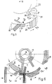
- FIG. 6 An alternative embodiment of a cutting device 8 in cooperation with the conveying device 4 is illustrated in FIG. 6.
- the cutting device 8 consists of a support 12 equipped with knives 11 on the circumference, which is driven on the shaft 17 about the axis 13, so that it moves in the cutting area on the conveyor 4 in the same direction as this, but at a higher speed.
- the same direction of rotation as the knives, but the speed of the conveying device 4 have the strips 15 of the drum-shaped supporting device 14, which are coaxial with the axis 13 and surround the rotating cutting device 8, the trailing shoulder 16 of which supports a printed product 2 on the notice board.
- a counter strip 24 of a counter-holding element directed against the shoulder 16 is again provided, which, however, in this embodiment according to FIG. 6 is pressed against the printed product 2 by cutting by accelerating its rotational speed. 24 'conveys the position of the counter bar after cutting in the starting position.
Claims (11)
- Dispositif pour la coupe d'un bord de produits d'impression (2) amenés en continu et placés à intervalles réguliers sur un dispositif transporteur (4) formé d'unités de transport (3), en carrousel, en forme de poches pouvant être alimentées par le dessus, les bords des produits imprimés dépassant au niveau des unités de transport (3) traversant un dispositif de coupe (8) disposé latéralement contre le dispositif transporteur (4), dans lequel un dispositif d'appui (14) présentant au moins un épaulement (16), placé à l'arrière des produits d'impression (2), décalé vers l'arrière par rapport au bord dépassant et opposé au couteau (11) lors du procédé de coupe, pouvant être amené en position au moins approximativement sur la longueur de coupe, et entraíné dans le même sens et selon la cadence des produits d'impression (2) amenés, est coordonné au dispositif de coupe (8) formé d'au moins un couteau (11), caractérisé en ce que le dispositif d'appui (14) est conçu de façon à pouvoir pivoter autour d'un axe (13) disposé parallèlement au bord de coupe, et en ce que le couteau (11) est fixé de façon concentrique à un support (12) pivotant par rapport au dispositif d'appui (14) et à l'intérieur de celui-ci.
- Dispositif selon la revendication 1, caractérisé en ce que le dispositif d'appui (14) présente sur sa périphérie plusieurs épaulements (16) séparés par intervalles sur les unités de transport (3) et agissant de façon concourante avec ces dernières.
- Dispositif selon la revendication 2, caractérisé en ce que les épaulements (16) du dispositif d'appui (14) sont conçus comme un contre-couteau agissant de façon concourante avec au moins un couteau (11).
- Dispositif selon la revendication 2 ou 3, caractérisé en ce que le support (12) est conçu de façon à recevoir plusieurs couteaux (11) répartis sur la circonférence.
- Dispositif selon la revendication 2, 3 ou 4, caractérisé en ce que les épaulements (16) sont chacun disposés, dans la direction du mouvement, sur le bord avant de baguettes (15) formées des génératrices du dispositif d'appui (14) en forme de tambour.
- Dispositif selon la revendication 5, caractérisé en ce qu'une contre-baguette (24), disposée entre les baguettes (15), commandée conjointement au dispositif d'appui (14) et agissant de façon souple en se comprimant contre le produit d'impression appuyé (2) lors du procédé de coupe, est coordonnée aux épaulements (16), respectivement sur chaque côté opposé des produits d'impression (2) affleurants.
- Dispositif selon la revendication 6, caractérisé en ce que la contre-baguette (24) est fixée des deux côtés du dispositif d'appui (14) sur une suspension (19), qui est reliée à un dispositif à levier (22) pouvant être actionné contre la force d'un ressort.
- Dispositif selon la revendication 7, caractérisé en ce que la suspension (19) est formée par deux disques (20) placés de façon orientable au niveau coaxial par rapport au dispositif d'appui (14), la suspension étant accouplée, pour enlever la contre-baguette (15) du produit d'impression (2), avec l'extrémité d'un bras de levier (26) du dispositif à levier (22) placé de façon pivotante sur le dispositif d'appui (14), l'autre bras de levier (27) étant relié à un rail de commande (23).
- Dispositif selon l'une des revendications 1 à 8, caractérisé en ce que l'écart vertical entre l'axe (13) et le dispositif transporteur (4) est modifiable.
- Dispositif selon la revendication 1, caractérisé en ce que le dispositif de coupe (8) présente un couteau (11) agissant de façon opposée à la direction de transport des produits d'impression (2).
- Dispositif selon l'une des revendications 1 à 10, caractérisé en ce que le dispositif d'appui (14) et le dispositif transporteur (4) peuvent être entraínés, dans la zone de coupe des produits d'impression (2), dans le même sens et avec la même vitesse, et en ce que le support (12) présentant au moins un couteau (11) peut être entraíné, dans la zone de coupe des produits d'impression (2), dans le même sens que le dispositif d'appui (14) tournant de façon coaxiale et que le dispositif transporteur (4), mais avec une vitesse de rotation plus importante.
Applications Claiming Priority (2)
| Application Number | Priority Date | Filing Date | Title |
|---|---|---|---|
| CH00768/94A CH687371A5 (de) | 1994-03-16 | 1994-03-16 | Einrichtung zum Beschneiden von Druckprodukten. |
| CH768/94 | 1994-03-16 |
Publications (2)
| Publication Number | Publication Date |
|---|---|
| EP0673729A1 EP0673729A1 (fr) | 1995-09-27 |
| EP0673729B1 true EP0673729B1 (fr) | 1998-07-22 |
Family
ID=4194726
Family Applications (1)
| Application Number | Title | Priority Date | Filing Date |
|---|---|---|---|
| EP95810155A Expired - Lifetime EP0673729B1 (fr) | 1994-03-16 | 1995-03-09 | Dispositif pour la coupe de produits imprimés |
Country Status (4)
| Country | Link |
|---|---|
| US (1) | US5832799A (fr) |
| EP (1) | EP0673729B1 (fr) |
| CH (1) | CH687371A5 (fr) |
| DE (1) | DE59502858D1 (fr) |
Cited By (1)
| Publication number | Priority date | Publication date | Assignee | Title |
|---|---|---|---|---|
| US8783150B2 (en) | 2003-10-02 | 2014-07-22 | Muller Martini Holding Ag | Device for trimming a print product |
Families Citing this family (8)
| Publication number | Priority date | Publication date | Assignee | Title |
|---|---|---|---|---|
| CH687371A5 (de) * | 1994-03-16 | 1996-11-29 | Grapha Holding Ag | Einrichtung zum Beschneiden von Druckprodukten. |
| CH690323A5 (de) * | 1995-10-04 | 2000-07-31 | Ferag Ag | Verfahren und Vorrichtung zum Schneiden von kontinuierlich geforderten, flochigen Produkten insbesondere aus Papier. |
| US6615699B2 (en) * | 1999-09-17 | 2003-09-09 | Ferag Ag | Method and device for cutting continuously conveyed, flat objects |
| US7926396B2 (en) * | 2001-10-26 | 2011-04-19 | Goss International Americas, Inc. | Matched velocity transfer apparatus for a sheet material article trimmer |
| US20070020578A1 (en) * | 2005-07-19 | 2007-01-25 | Scott Robert R | Dental curing light having a short wavelength LED and a fluorescing lens for converting wavelength light to curing wavelengths and related method |
| CH704642B1 (de) * | 2005-01-21 | 2012-09-28 | Ferag Ag | Vorrichtung zum Beschneiden flexibler, flächiger Produkte. |
| EP1683612B1 (fr) * | 2005-01-21 | 2016-08-03 | Ferag AG | Procédé et dispositif pour transporter des produits plats flexibles, et pour les découper au même temps |
| DE102017120026A1 (de) * | 2017-07-12 | 2019-01-17 | Bw Papersystems Hamburg Gmbh | Querschneider und Verfahren zur material- und/oder dickenabhängigen Anpassung der relativen Schnittposition eines umlaufenden Messers zur Schnittposition eines feststehenden Messers bei einem Querschneider |
Family Cites Families (11)
| Publication number | Priority date | Publication date | Assignee | Title |
|---|---|---|---|---|
| DE308330C (fr) * | 1900-01-01 | |||
| CH410763A (de) * | 1964-04-22 | 1966-03-31 | Sig Schweiz Industrieges | Schervorrichtung zum Zerschneiden einer Materialbahn |
| DE1778882A1 (de) * | 1968-06-14 | 1971-09-02 | Karl Schnell | Zerkleinerungsmaschine mit zylindrischem Siebkoerper |
| CH584153A5 (fr) * | 1973-10-10 | 1977-01-31 | Ferag Ag | |
| CH583611A5 (fr) * | 1975-04-08 | 1977-01-14 | Ferag Ag | |
| CH618398A5 (fr) * | 1977-06-06 | 1980-07-31 | Ferag Ag | |
| CH668216A5 (en) * | 1985-11-14 | 1988-12-15 | Ferag Ag | Printed item-trimming machine - has compartments and knives on parallel endless chains travelling at same speed |
| CA1330033C (fr) * | 1988-10-31 | 1994-06-07 | Walter Reist | Methode et appareil de coupe de produits imprimes |
| DE3931158A1 (de) * | 1989-09-19 | 1991-03-28 | Roland Man Druckmasch | Vorrichtung fuer den dreiseitigen beschnitt von druckexemplaren |
| DE4243059C2 (de) * | 1992-12-18 | 1994-09-22 | Ferag Ag | Einrichtung zum Beschneiden von flächigen Erzeugnissen, insbesondere mehrblättrigen Druckerzeugnissen |
| CH687371A5 (de) * | 1994-03-16 | 1996-11-29 | Grapha Holding Ag | Einrichtung zum Beschneiden von Druckprodukten. |
-
1994
- 1994-03-16 CH CH00768/94A patent/CH687371A5/de not_active IP Right Cessation
-
1995
- 1995-03-09 DE DE59502858T patent/DE59502858D1/de not_active Expired - Lifetime
- 1995-03-09 EP EP95810155A patent/EP0673729B1/fr not_active Expired - Lifetime
-
1997
- 1997-09-08 US US08/925,314 patent/US5832799A/en not_active Expired - Lifetime
Cited By (1)
| Publication number | Priority date | Publication date | Assignee | Title |
|---|---|---|---|---|
| US8783150B2 (en) | 2003-10-02 | 2014-07-22 | Muller Martini Holding Ag | Device for trimming a print product |
Also Published As
| Publication number | Publication date |
|---|---|
| DE59502858D1 (de) | 1998-08-27 |
| CH687371A5 (de) | 1996-11-29 |
| EP0673729A1 (fr) | 1995-09-27 |
| US5832799A (en) | 1998-11-10 |
Similar Documents
| Publication | Publication Date | Title |
|---|---|---|
| DE2514836C2 (de) | Vorrichtung zum Durchschneiden eines Bogenstapels mit einem Rundmesser | |
| DE4402560C2 (de) | Vorrichtung zum Drehen von flachliegend voranbewegten Werkstücken | |
| DE4040877B4 (de) | Vorrichtung zum Zuführen von Druckerzeugnissen zu einer Beschneidemaschine | |
| DE2922164C2 (fr) | ||
| EP0673729B1 (fr) | Dispositif pour la coupe de produits imprimés | |
| DE19830489A1 (de) | Schneidvorrichtung für flache Produkte | |
| CH678160A5 (fr) | ||
| DE3335430C2 (fr) | ||
| CH689449A5 (de) | Verfahren zum Beschneiden von flachen Druckprodukten laengs einer vorgegebenen Schnittlinie. | |
| DE3244422A1 (de) | Schneidevorrichtung fuer bogen sowie hefte mit mindestens einem rotierenden schneidmesser und einer foerdervorrichtung | |
| EP0686463A1 (fr) | Dispositif pour couper des imprimés, notamment des journaux, des magazines ou des brochures, au moins des deux cotés | |
| DE2614651C3 (de) | Vorrichtung zum Herstellen von Mehr-Komponenten-Filterstäben der tabakverarbeitenden Industrie | |
| EP0450338B1 (fr) | Procédé pour découper latéralement des produits d'impression consistant en papier à plat | |
| DE2741559C3 (de) | Längsschneideeinrichtung | |
| DE19612924A1 (de) | Vorrichtung zum automatischen Zuführen eines Endes einer Materialbahn | |
| DE2901631C2 (fr) | ||
| DE3636965C2 (fr) | ||
| DE3022772A1 (de) | Vorrichtung zum schneiden von prospekten, bedruckten blaettern o.dgl. gegenstaenden | |
| DE2902671C2 (de) | Vorrichtung zum Zerschneiden eines flexiblen, bandartigen Materials | |
| DE3812170C2 (fr) | ||
| DE3712522C2 (fr) | ||
| EP0793916A1 (fr) | Machine pour l'enlèvement d'une couche superficielle en particulier de filets de poissons | |
| DE1910385B2 (de) | Schneidevorrichtung zum Schneiden von Teeblättern | |
| EP0208244B1 (fr) | Dispositif pour rogner des produits imprimés délivrés en chevauchement | |
| DE3413912A1 (de) | Verfahren und vorrichtung zum schlitzen eines brotproduktes |
Legal Events
| Date | Code | Title | Description |
|---|---|---|---|
| PUAI | Public reference made under article 153(3) epc to a published international application that has entered the european phase |
Free format text: ORIGINAL CODE: 0009012 |
|
| AK | Designated contracting states |
Kind code of ref document: A1 Designated state(s): DE FR GB IT |
|
| 17P | Request for examination filed |
Effective date: 19960112 |
|
| 17Q | First examination report despatched |
Effective date: 19970320 |
|
| GRAG | Despatch of communication of intention to grant |
Free format text: ORIGINAL CODE: EPIDOS AGRA |
|
| GRAG | Despatch of communication of intention to grant |
Free format text: ORIGINAL CODE: EPIDOS AGRA |
|
| GRAH | Despatch of communication of intention to grant a patent |
Free format text: ORIGINAL CODE: EPIDOS IGRA |
|
| GRAH | Despatch of communication of intention to grant a patent |
Free format text: ORIGINAL CODE: EPIDOS IGRA |
|
| GRAA | (expected) grant |
Free format text: ORIGINAL CODE: 0009210 |
|
| AK | Designated contracting states |
Kind code of ref document: B1 Designated state(s): DE FR GB IT |
|
| REF | Corresponds to: |
Ref document number: 59502858 Country of ref document: DE Date of ref document: 19980827 |
|
| GBT | Gb: translation of ep patent filed (gb section 77(6)(a)/1977) |
Effective date: 19980910 |
|
| ET | Fr: translation filed | ||
| PLBE | No opposition filed within time limit |
Free format text: ORIGINAL CODE: 0009261 |
|
| STAA | Information on the status of an ep patent application or granted ep patent |
Free format text: STATUS: NO OPPOSITION FILED WITHIN TIME LIMIT |
|
| 26N | No opposition filed | ||
| REG | Reference to a national code |
Ref country code: GB Ref legal event code: IF02 |
|
| PGFP | Annual fee paid to national office [announced via postgrant information from national office to epo] |
Ref country code: FR Payment date: 20120405 Year of fee payment: 18 |
|
| PGFP | Annual fee paid to national office [announced via postgrant information from national office to epo] |
Ref country code: DE Payment date: 20120327 Year of fee payment: 18 |
|
| PGFP | Annual fee paid to national office [announced via postgrant information from national office to epo] |
Ref country code: GB Payment date: 20120327 Year of fee payment: 18 Ref country code: IT Payment date: 20120326 Year of fee payment: 18 |
|
| GBPC | Gb: european patent ceased through non-payment of renewal fee |
Effective date: 20130309 |
|
| REG | Reference to a national code |
Ref country code: FR Ref legal event code: ST Effective date: 20131129 |
|
| REG | Reference to a national code |
Ref country code: DE Ref legal event code: R119 Ref document number: 59502858 Country of ref document: DE Effective date: 20131001 |
|
| PG25 | Lapsed in a contracting state [announced via postgrant information from national office to epo] |
Ref country code: FR Free format text: LAPSE BECAUSE OF NON-PAYMENT OF DUE FEES Effective date: 20130402 Ref country code: GB Free format text: LAPSE BECAUSE OF NON-PAYMENT OF DUE FEES Effective date: 20130309 Ref country code: DE Free format text: LAPSE BECAUSE OF NON-PAYMENT OF DUE FEES Effective date: 20131001 |
|
| PG25 | Lapsed in a contracting state [announced via postgrant information from national office to epo] |
Ref country code: IT Free format text: LAPSE BECAUSE OF NON-PAYMENT OF DUE FEES Effective date: 20130309 |