EP0673729B1 - Device for cutting printed products - Google Patents
Device for cutting printed products Download PDFInfo
- Publication number
- EP0673729B1 EP0673729B1 EP95810155A EP95810155A EP0673729B1 EP 0673729 B1 EP0673729 B1 EP 0673729B1 EP 95810155 A EP95810155 A EP 95810155A EP 95810155 A EP95810155 A EP 95810155A EP 0673729 B1 EP0673729 B1 EP 0673729B1
- Authority
- EP
- European Patent Office
- Prior art keywords
- printed products
- trimming
- supporting device
- knife
- cutting
- Prior art date
- Legal status (The legal status is an assumption and is not a legal conclusion. Google has not performed a legal analysis and makes no representation as to the accuracy of the status listed.)
- Expired - Lifetime
Links
Images
Classifications
-
- B—PERFORMING OPERATIONS; TRANSPORTING
- B26—HAND CUTTING TOOLS; CUTTING; SEVERING
- B26D—CUTTING; DETAILS COMMON TO MACHINES FOR PERFORATING, PUNCHING, CUTTING-OUT, STAMPING-OUT OR SEVERING
- B26D7/00—Details of apparatus for cutting, cutting-out, stamping-out, punching, perforating, or severing by means other than cutting
- B26D7/06—Arrangements for feeding or delivering work of other than sheet, web, or filamentary form
- B26D7/0675—Arrangements for feeding or delivering work of other than sheet, web, or filamentary form specially adapted for piles of sheets
-
- B—PERFORMING OPERATIONS; TRANSPORTING
- B26—HAND CUTTING TOOLS; CUTTING; SEVERING
- B26D—CUTTING; DETAILS COMMON TO MACHINES FOR PERFORATING, PUNCHING, CUTTING-OUT, STAMPING-OUT OR SEVERING
- B26D1/00—Cutting through work characterised by the nature or movement of the cutting member or particular materials not otherwise provided for; Apparatus or machines therefor; Cutting members therefor
- B26D1/01—Cutting through work characterised by the nature or movement of the cutting member or particular materials not otherwise provided for; Apparatus or machines therefor; Cutting members therefor involving a cutting member which does not travel with the work
- B26D1/12—Cutting through work characterised by the nature or movement of the cutting member or particular materials not otherwise provided for; Apparatus or machines therefor; Cutting members therefor involving a cutting member which does not travel with the work having a cutting member moving about an axis
- B26D1/25—Cutting through work characterised by the nature or movement of the cutting member or particular materials not otherwise provided for; Apparatus or machines therefor; Cutting members therefor involving a cutting member which does not travel with the work having a cutting member moving about an axis with a non-circular cutting member
- B26D1/34—Cutting through work characterised by the nature or movement of the cutting member or particular materials not otherwise provided for; Apparatus or machines therefor; Cutting members therefor involving a cutting member which does not travel with the work having a cutting member moving about an axis with a non-circular cutting member moving about an axis parallel to the line of cut
- B26D1/38—Cutting through work characterised by the nature or movement of the cutting member or particular materials not otherwise provided for; Apparatus or machines therefor; Cutting members therefor involving a cutting member which does not travel with the work having a cutting member moving about an axis with a non-circular cutting member moving about an axis parallel to the line of cut and coacting with a fixed blade or other fixed member
-
- B—PERFORMING OPERATIONS; TRANSPORTING
- B26—HAND CUTTING TOOLS; CUTTING; SEVERING
- B26D—CUTTING; DETAILS COMMON TO MACHINES FOR PERFORATING, PUNCHING, CUTTING-OUT, STAMPING-OUT OR SEVERING
- B26D1/00—Cutting through work characterised by the nature or movement of the cutting member or particular materials not otherwise provided for; Apparatus or machines therefor; Cutting members therefor
- B26D1/56—Cutting through work characterised by the nature or movement of the cutting member or particular materials not otherwise provided for; Apparatus or machines therefor; Cutting members therefor involving a cutting member which travels with the work otherwise than in the direction of the cut, i.e. flying cutter
- B26D1/62—Cutting through work characterised by the nature or movement of the cutting member or particular materials not otherwise provided for; Apparatus or machines therefor; Cutting members therefor involving a cutting member which travels with the work otherwise than in the direction of the cut, i.e. flying cutter and is rotating about an axis parallel to the line of cut, e.g. mounted on a rotary cylinder
-
- B—PERFORMING OPERATIONS; TRANSPORTING
- B26—HAND CUTTING TOOLS; CUTTING; SEVERING
- B26D—CUTTING; DETAILS COMMON TO MACHINES FOR PERFORATING, PUNCHING, CUTTING-OUT, STAMPING-OUT OR SEVERING
- B26D7/00—Details of apparatus for cutting, cutting-out, stamping-out, punching, perforating, or severing by means other than cutting
- B26D7/01—Means for holding or positioning work
- B26D7/02—Means for holding or positioning work with clamping means
- B26D7/025—Means for holding or positioning work with clamping means acting upon planar surfaces
-
- B—PERFORMING OPERATIONS; TRANSPORTING
- B26—HAND CUTTING TOOLS; CUTTING; SEVERING
- B26D—CUTTING; DETAILS COMMON TO MACHINES FOR PERFORATING, PUNCHING, CUTTING-OUT, STAMPING-OUT OR SEVERING
- B26D7/00—Details of apparatus for cutting, cutting-out, stamping-out, punching, perforating, or severing by means other than cutting
- B26D2007/0012—Details, accessories or auxiliary or special operations not otherwise provided for
- B26D2007/0081—Cutting on three sides, e.g. trilateral trimming
-
- Y—GENERAL TAGGING OF NEW TECHNOLOGICAL DEVELOPMENTS; GENERAL TAGGING OF CROSS-SECTIONAL TECHNOLOGIES SPANNING OVER SEVERAL SECTIONS OF THE IPC; TECHNICAL SUBJECTS COVERED BY FORMER USPC CROSS-REFERENCE ART COLLECTIONS [XRACs] AND DIGESTS
- Y10—TECHNICAL SUBJECTS COVERED BY FORMER USPC
- Y10S—TECHNICAL SUBJECTS COVERED BY FORMER USPC CROSS-REFERENCE ART COLLECTIONS [XRACs] AND DIGESTS
- Y10S83/00—Cutting
- Y10S83/929—Particular nature of work or product
- Y10S83/934—Book, being made, e.g. trimming a signature
-
- Y—GENERAL TAGGING OF NEW TECHNOLOGICAL DEVELOPMENTS; GENERAL TAGGING OF CROSS-SECTIONAL TECHNOLOGIES SPANNING OVER SEVERAL SECTIONS OF THE IPC; TECHNICAL SUBJECTS COVERED BY FORMER USPC CROSS-REFERENCE ART COLLECTIONS [XRACs] AND DIGESTS
- Y10—TECHNICAL SUBJECTS COVERED BY FORMER USPC
- Y10T—TECHNICAL SUBJECTS COVERED BY FORMER US CLASSIFICATION
- Y10T83/00—Cutting
- Y10T83/647—With means to convey work relative to tool station
- Y10T83/6476—Including means to move work from one tool station to another
- Y10T83/6483—Tool stations staggered relative to one another
-
- Y—GENERAL TAGGING OF NEW TECHNOLOGICAL DEVELOPMENTS; GENERAL TAGGING OF CROSS-SECTIONAL TECHNOLOGIES SPANNING OVER SEVERAL SECTIONS OF THE IPC; TECHNICAL SUBJECTS COVERED BY FORMER USPC CROSS-REFERENCE ART COLLECTIONS [XRACs] AND DIGESTS
- Y10—TECHNICAL SUBJECTS COVERED BY FORMER USPC
- Y10T—TECHNICAL SUBJECTS COVERED BY FORMER US CLASSIFICATION
- Y10T83/00—Cutting
- Y10T83/647—With means to convey work relative to tool station
- Y10T83/654—With work-constraining means on work conveyor [i.e., "work-carrier"]
- Y10T83/6542—Plural means to constrain plural work pieces
-
- Y—GENERAL TAGGING OF NEW TECHNOLOGICAL DEVELOPMENTS; GENERAL TAGGING OF CROSS-SECTIONAL TECHNOLOGIES SPANNING OVER SEVERAL SECTIONS OF THE IPC; TECHNICAL SUBJECTS COVERED BY FORMER USPC CROSS-REFERENCE ART COLLECTIONS [XRACs] AND DIGESTS
- Y10—TECHNICAL SUBJECTS COVERED BY FORMER USPC
- Y10T—TECHNICAL SUBJECTS COVERED BY FORMER US CLASSIFICATION
- Y10T83/00—Cutting
- Y10T83/647—With means to convey work relative to tool station
- Y10T83/658—With projections on work-carrier [e.g., pin wheel]
Landscapes
- Life Sciences & Earth Sciences (AREA)
- Forests & Forestry (AREA)
- Engineering & Computer Science (AREA)
- Mechanical Engineering (AREA)
- Details Of Cutting Devices (AREA)
- Separation, Sorting, Adjustment, Or Bending Of Sheets To Be Conveyed (AREA)
Description
Die Erfindung betrifft eine Einrichtung zum Beschneiden mindestens einer Kante von in regelmässigen Abständen einer aus umlaufenden, von oben beschickbaren taschenartigen Fördereinheiten gebildeten Fördervorrichtung ununterbrochen zugeführten Druckprodukten, deren an den Fördereinheiten vorstehenden Kanten eine an der Fördervorrichtung seitlich angeordnete Schneidvorrichtung durchsetzen, wobei der aus wenigstens einem Messer gebildeten Schneidvorrichtung eine an der Rückseite der Druckprodukte, von der vorstehenden Kante zurückversetzte und beim Schneidvorgang dem Messer gegenüberliegend, wenigstens annähernd über die Schnittlänge in Anlage bringbare, gleichsinnig und im Takt der zugeführten Druckprodukte angetriebene, wenigstens eine Schulter aufweisende Stützvorrichtung zugeordnet ist.The invention relates to a device for trimming at least an edge from one at regular intervals encircling, bag-like conveyor units that can be loaded from above formed conveyor continuously fed Printed products whose edges protrude from the conveyor units one on the side of the conveyor Enforce cutting device, which consists of at least one Knife formed a cutting device at the back of the Printed products, set back from the protruding edge and opposite the knife during the cutting process, at least can be brought into contact in the same direction over the cutting length and driven in time with the supplied print products, associated with at least one shoulder supporting device is.
Eine solche Einrichtung ist durch die CH - A - 668 216 bekanntgeworden. Such a device has become known from CH - A - 668 216.
Als Schneidvorrichtung sind paarweise einander zugeordnete
Messer vorgesehen, die vereint in denselben Abständen wie die
taschenartigen Fördereinheiten der Fördervorrichtung an endlos
umlaufend angetriebenen Zugorganen befestigt sind, deren eines
Trum parallel zu einem Abschnitt der aus Zugorganen gebildeten
Fördervorrichtung verläuft und gleichsinnig sowie mit gleicher
Geschwindigkeit wie diese angetrieben ist.
D.h. in der Praxis, dass die aus den taschenartigen Fördereinheiten
zum Beschneiden herausragenden Kanten der Druckprodukte
zwischen die einander paarweise zugeordneten Messer einer ge
öffneten Schneidvorrichtung geführt und anschliessend auf den
durch die benachbarten parallelen Trums der Zugorgane der
Schneidvorrichtung und der Fördervorrichtung gebildeten gemeinsamen
Abschnitt ausgerichtet sowie fixiert und anschliessend
beschnitten werden.
Auf dem gemeinsamen Abschnitt ergibt sich bei der bekannten
Ausführung zwischen den Fördereinheiten und den Messerpaaren
der Schneidvorrichtung bzw. der Schnittkante ein respektabler
Abstand, der die geforderte Schnittqualität insbesondere bei
relativ dünnen Druckprodukten nicht gewährleistet.
Dickere Druckprodukte, bei denen eine höhere Schnittkraft notwendig
ist, sind aufgrund des erforderlichen Führungsspiels an
der vorgeschlagenen, kettengeführten Schneidvorrichtung und
der Fördervorrichtung sowie zwischen diesen einer unzuverlässigen
Schnittgenauigkeit ausgesetzt; hingegen bedarf es keiner
genauen Einstellung der Schnittposition entlang des gemeinsamen
Abschnittes von Fördervorrichtung und Schneidvorrichtung.Knives which are assigned to one another in pairs are provided as the cutting device, which are joined together at the same intervals as the pocket-like conveying units of the conveying device to endlessly driven traction elements, one strand of which runs parallel to a section of the conveying device formed from tractive elements and is driven in the same direction and at the same speed as this is.
In practice, this means that the edges of the printed products protruding from the pocket-like conveying units for trimming are guided between the knives of an open cutting device which are assigned to one another in pairs and then aligned and fixed to the common section formed by the adjacent parallel runs of the traction elements of the cutting device and the conveying device and then be trimmed.
On the common section there is a respectable distance between the conveyor units and the knife pairs of the cutting device or the cutting edge in the known embodiment, which does not guarantee the required cutting quality, particularly in the case of relatively thin printed products.
Thicker printed products, for which a higher cutting force is required, are exposed to an unreliable cutting accuracy due to the required guide play on the proposed chain-guided cutting device and the conveyor device, and between these; on the other hand, no exact adjustment of the cutting position along the common section of the conveyor and cutting device is required.
Die EP - A - 0 367 715 vermittelt ein Verfahren zum Beschneiden
der Seitenkanten von kontinuierlich geförderten Druckprodukten
in einem Durchlauf-Prozess, wobei jedem Druckprodukt
ein nachlaufender förderwirksamer erster Messerteil zugeordnet
ist, welcher das Druckprodukt mit im wesentlich gleicher Geschwindigkeit
bewegt resp. antreibt und entlang einer vorgesehenen
Schnittkante zueinander in Anlage bringt, derart, dass
der erste Messerteil, der der Fördereinheit einer Fördervorrichtung
entspricht, und das zu ihm gehörige Druckprodukt, an
einem zweiten ortsfesten Messerteil vorbeigeführt werden, um
mit diesem in Schneideingriff gebracht zu werden. Hierzu wird
eine Vorrichtung vorgeschlagen, die eine Fördervorrichtung mit
mehreren auf einem geschlossenen Pfad umlaufenden Fördereinheiten
zur Aufnahme der kontinuierlich anfallenden Druckprodukte
aufweist, wobei die Fördereinheiten an der Rückseite der
Druckprodukte ein Gegenmesser enthalten und Mittel besitzen,
um die Druckprodukte in den Fördereinheiten wenigstens entlang
der vorgesehenen Schnittkante mit dem Gegenmesser in Anlage zu
bringen, bevor sie ein ortsfestes Schneidmesser bzw. zweites
Messerteil durchlaufen, das mit dem Gegenmesser bzw. ersten
Messerteil jeder Fördereinheit zusammenwirkt, und somit entlang
der gebildeten Schnittkante beschnitten werden.
Eine solche Ausführung erfordert aufgrund der schlagartig einwirkenden
Schnittkräfte einen hohen Konstruktionsaufwand, um
eine die notwendige Schnittqualität vermittelnde Stabilität
mit den Fördereinheiten erreichen zu können. Es erweist sich
somit auf den Schneidvorgang als ungünstig, wenn die an Zugorganen
aufgehängten und in Längsführungen mit seitlichem
Spiel fortbewegten Fördereinheiten hohen Belastungen ausgesetzt
werden.EP - A - 0 367 715 conveys a method for trimming the side edges of continuously conveyed printed products in a continuous process, with each printed product being assigned a trailing, first knife part which is effective in conveying and which moves or moves the printed product at substantially the same speed. drives and brings into contact with one another along a provided cutting edge, such that the first knife part, which corresponds to the conveying unit of a conveying device, and the printed product belonging to it, are guided past a second stationary knife part in order to be brought into cutting engagement therewith. For this purpose, a device is proposed which has a conveying device with a plurality of conveying units rotating on a closed path for receiving the continuously occurring printed products, the conveying units on the back of the printed products containing a counter knife and having means for conveying the printed products in the conveying units at least along the intended Bring the cutting edge into contact with the counter knife before they pass through a stationary cutting knife or second knife part, which cooperates with the counter knife or first knife part of each conveyor unit, and are thus trimmed along the formed cutting edge.
Due to the sudden cutting forces, such a design requires a high level of design effort in order to be able to achieve a stability with the conveyor units that conveys the necessary cutting quality. It thus turns out to be unfavorable for the cutting process if the conveyor units suspended on traction elements and moved in longitudinal guides with lateral play are exposed to high loads.
Aufgabe der Erfindung ist es somit, eine Einrichtung zum Beschneiden von Druckprodukten nach der eingangs genannten Art zu schaffen, bei welcher durch eine gegenüber den bekannten Konstruktionen unterschiedliche Bauweise die erwähnten Nachteile nicht eintreten bzw. bei der die geforderte Schnittqualität und die dafür erforderliche Eigenstabilität auf einfache Weise erzielt werden kann.The object of the invention is therefore a device for trimming of printed products according to the aforementioned type to create, in which by a compared to the known Constructions different construction the disadvantages mentioned do not occur or where the required cut quality and the inherent stability required for this in a simple manner Way can be achieved.
Erfindungsgemäss wird diese Aufgabe
in der eingangsgenannten Einrichtung
dadurch gelöst, dass die
Stützvorrichtung um eine parallel zur Schnittkante angeordnete
Achse rotierbar ausgebildet und das Messer konzentrisch an
einem zu der Stützvorrichtung und innerhalb dieser drehbaren
Support befestigt ist.
Diese Ausgestaltung gestattet es, die durch den Schneidvorgang
auftretenden Kräfte von der Fördervorrichtung fernzuhalten und
den Schneidvorgang in stabiler Umgebung durchzuführen.According to the invention, this object is achieved in the device mentioned at the outset in that the support device is designed to be rotatable about an axis arranged parallel to the cutting edge and the knife is fixed concentrically to a support which is rotatable with respect to and within the support device.
This configuration makes it possible to keep the forces arising from the cutting process away from the conveyor device and to carry out the cutting process in a stable environment.
In dem anschliesenden Beschreibungsteil wird die erfindungsgemässe Einrichtung anhand eines in der Zeichnung dargestellten Ausführungsbeispiels erörtert. Es zeigen:
- Fig. 1
- eine schematische Darstellung der konstruktiven Ausgestaltung und Anordnungsweise der erfindungsgemässen Einrichtung,
- Fig. 2
- einen Querschnitt nach der Linie II - II in Fig. 3,
- Fig. 3
- auszugsweise einen vergrösserten Grundriss der Darstellung in Fig. 1,
- Fig. 4
- einen auszugsweisen Längsschnitt nach der Linie IV - IV in Fig. 3,
- Fig. 5
- eine schematische Darstellung der konstruktiven Mittel zur Betätigung des in den Fig. 4 und 6 veranschaulichten Gegenhalteorgans und
- Fig. 6
- einen auszugsweisen Längsschnitt gemäss Linie IV - IV in Fig. 3 mit einer alternativen Ausführungsform.
- Fig. 1
- 2 shows a schematic representation of the structural design and arrangement of the device according to the invention,
- Fig. 2
- 3 shows a cross section along the line II-II in FIG. 3,
- Fig. 3
- extracts an enlarged plan view of the representation in Fig. 1,
- Fig. 4
- an excerpt longitudinal section along the line IV - IV in Fig. 3,
- Fig. 5
- is a schematic representation of the constructive means for actuating the counter-holding element illustrated in FIGS. 4 and 6
- Fig. 6
- an excerpt longitudinal section along line IV - IV in Fig. 3 with an alternative embodiment.
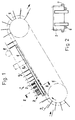
Fig. 1 zeigt eine Einrichtung 1 zum Beschneiden mehrerer Kanten
von in regelmässigen Abständen beispielsweise von einer
Rotationsdruckmaschine oder einem Sammelhefter zugeführten
Druckprodukten 2. Letztere werden von oben beschickbaren taschenartigen
Fördereinheiten 3 einer Fördervorrichtung 4 zum
Transport aufgegeben. Die Fördereinheiten 3 sind mit endlos um
wenigstens zwei beabstandete Rollen 5 umlaufend angetriebenen
Zugorganen 6 und hinsichtlich ihres Aufnahmevermögens möglicherweise
einstellbar ausgebildet bzw. an die Grösse des Ladegutes
resp. der Druckprodukte 2, die beim Schneidvorgang in
den Fördereinheiten eingespannt sind, angepasst. Der Verlauf
der Trums der Fördervorrichtung 4 ist schräg nach oben vorgesehen,
sodass die in den Fördereinheiten 3 vorkommenden Druckprodukte
2 flach gestreckt an der Rückwand der Fördereinheiten
3 anliegen können. Nicht ersichtliche Halteelemente sorgen
dafür, dass die Druckprodukte 2, nachdem sie die Lage zum Beschneiden
der Kanten beispielsweise mit Hilfe von Führungsmitteln
eingenommen haben, an der Rückwand der Fördereinheiten 3
festgehalten werden.
Bezüglich der Positionierung der Druckprodukte 2, sind unterhalb
der Fördereinheiten 3 zwei voneinander in seitlichem Abstand
angeordnete, den Druckprodukten 2 eine Abstützfläche
bietende und vorzugsweise mit gleicher Geschwindigkeit mitlaufende
endlos angetriebene Bänder 6 vorgesehen, die auch in
Fig. 2 erkennbar sind. Die seitliche Führung der Druckprodukte
2 erfolgt auf ähnliche Weise durch seitlich der Fördervorrichtung
4 angeordnete, vorzugsweise verstellbare Führungsbänder 7
(siehe auch Fig. 3). Es könnten zu diesem Zweck auch statische
Abweisorgane oder andere bekannte Mittel verwendet werden.
Selbstverständlich ist der schräg nach oben gerichtete Verlauf
der Fördervorrichtung 4, der ein flaches Aufliegen der zugeführten
Druckprodukte 2 in den Fördereinheiten 3 begünstigt,
nicht zwingend, sie könnte auch waagrecht angeordnet sein.
Die von den Kanten der Druckprodukte 2 zurückversetzten
strichpunktierten Linien in den Fig. 1 bis 3 weisen auf die
Schneidkanten der Druckprodukte 2 hin, wobei in Fig. 1 die
Schneidkante für die offene Seitenkante der Druckprodukte 2
angegeben, in Fig. 2 Kopf-, Fuss- und Seitenkante und in Fig.
3 wiederum Kopf- und Fusskante vermerkt sind.
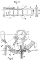
In Fig. 4 ist eine zur Einrichtung 1 gehörende Schneidvorrichtung
8 veranschaulicht, wie sie beispielsweise in den Fig. 1
und 3 anordnungsmässig dargestellt ist. Bezugszeichen 9 deutet
jeweils auf die Schnittkanten für Kopf- und/oder Fussseite
oder die zu beschneidende offene Seitenkante eines Druckproduktes
2 hin. An der Schnittkante 9 liegt die der Förderrichtung
der Druckprodukte entgegengerichtete Schneide 10 eines
stationären, über die maximale Breite der Seiten eines Druckproduktes
2 hinausragenden Messers 11, das an einem Support 12
abnehmbar befestigt ist.1 shows a device 1 for trimming several edges of printed
With regard to the positioning of the printed
FIG. 4 illustrates a cutting device 8 belonging to the device 1, as is shown in the arrangement, for example, in FIGS. 1 and 3.
Die Schneide kann von der Senkrechten zur Förderrichtung abweichend
in einem schrägen Winkel sich über die Schnittlänge
erstreckend ausgebildet sein, sodass der Schnitt über eine
kurze Zeit durchgeführt wird. Der Support 12 ist um eine senkrecht
zur Förderrichtung und parallel zur Schnittkante verlaufende
Achse 13 drehbar angeordnet, deren Abstand senkrecht zu
der Fördervorrichtung veränderbar ausgebildet ist. Auch parallel
zur Förderrichtung kann die Schneide 10 des Messers 11
verstellt werden.
Der Fördervorrichtung 4 bzw. jeder Fördereinheit 3 ist eine im
Schneidbereich um die Achse 13 gleichsinnig rotierend angetriebene
Stützvorrichtung 14 zugeordnet, die im Takt der der
Fördervorrichtung 4 zugeführten resp. von der Fördervorrichtung
4 transportierten Druckprodukte 2 vor und während dem
Schneidvorgang an der Rückseite der Druckprodukte 2, diese unterhalb
der Schneidkante 9 stützend anliegt. Die trommelförmig
ausgebildete Stützvorrichtung 14 weist am Umfang verteilt,
mehrere parallel zu den Mantellinien verlaufende, einen rotierenden
Käfig bildende Leisten 15 auf, die an der in Drehrichtung
vorderen Kante als an den Rückseiten der Druckprodukte 2
von der Schneidkante 9 zurückversetzt anliegende Schultern 16
ausgebildet sind. Die Abstände der Schultern 16 am Umfang der
Stützvorrichtung 14 entsprechen den Abständen der Fördereinheiten
3 an der Fördervorrichtung 4, können aber auch kürzer
oder länger gewählt werden.
Um die Schnittleistung verbessern zu können, kann die Schulter
16 als Gegenmesser ausgebildet sein, wozu das der Schneide 10
des Messers 11 zugewendete Ende als Schneidkante wirkt. Es ist
vorteilhaft, wenn die Schultern 16 austauschbar an den Leisten
15, wie das Messer am Support 12 befestigt sind. Die die
Schultern 16 besitzenden Leisten 15 sind als Abschnitte einer
um die Achse 13 umlaufenden Trommel ausgebildet und ergeben
einen käfigartigen Rotor.
Der Support 12 kann auch für mehrere zu befestigende Messer 11
ausgebildet sein, sowohl bei stationär eingesetztem Messer,
sodass ein schneller Messerwechsel durchführbar wird; als auch
bei rotierend angetriebener Schneidvorrichtung 8, bei welcher
ein oder mehrere Messer 11 im Schneidbereich der Fördervorrichtung
4 entgegenwirken bzw. im Bereich ihrer grössten Annäherung
an die Fördervorrichtung 4 mit den Schultern 16 der
Stützvorrichtung zusammenwirken. Zu diesem Zweck ist der Support
12 an einer Welle 17 gelagert.
Letztere und die Schneidvorrichtung 8 resp. der Support 12
können wie dargestellt und bei Querschneidern bekannt, zur
Späneabfuhr ausgebildet sein. Hierzu ist die Welle 17 hohl
ausgebildet, der Hohlraum an eine Druck- oder Vakuumquelle
angeschlossen und der Support 12 mit einem den Hohlraum der
Welle 17 mit dem Schneidbereich verbindenden sektorähnlichen
Abzugsraum 18 ausgestattet, der durch die ausserhalb des/der
Messer 11 umlaufenden Leisten 15 begrenzt wird.
Zur Erzielung einer hohen Schneidstabilität über dem von der
Stützvorrichtung 14 gegen Knicken gehaltenen Bereich eines
Druckbogens 2 kann mit Hilfe einer Gegenleiste 24 ein Gegenhalteorgan
gebildet werden, das sich von der Schulter 16 an
dem Druckprodukt 2 gegenüberliegend gegen dieses stemmt.The cutting edge can deviate from the perpendicular to the conveying direction at an oblique angle and extend over the cutting length, so that the cutting is carried out over a short time. The support 12 is arranged so as to be rotatable about an
The
In order to be able to improve the cutting performance, the
The support 12 can also be designed for a plurality of
The latter and the cutting device 8 respectively. the support 12 can, as shown and known in cross cutters, be designed to remove chips. For this purpose, the
In order to achieve a high cutting stability over the area of a printed
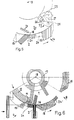
Fig. 5 vermittelt die konstruktiven Mittel und die Funktionsweise
der Gegenleiste 24 als Gegenhalteorgang. Letzteres ist
beidseits der Stützvorrichtung 14 an einer Aufhängung 19, bestehend
aus jeweils einer koaxial zur Achse 13 drehbar gelagerten
Scheibe 20, an deren Umfang die Gegenleiste 24 befestigt
ist. Die Gegenleiste 24 wird beispielsweise mit der
Kraft einer Feder oder pneumatisch, d.h. aufgrund der mit unterschiedlichen
Dickenmassen zu bearbeitenden Druckprodukte
nachgiebig gegen das Druckprodukt 2 resp. gegen die Schulter
16 gepresst. Dementsprechend ist in Fig. 5 eine Zugfeder 21
vermerkt, die jeweils an der Scheibe 20 angreift und dadurch
mitdrehend die Gegenleiste 24 an das strichpunktiert gezeichnete
Druckprodukt 2 anpresst.
Diese Anpresskraft kann durch eine auf die Scheiben 20 einwirkende,
gesteuerte Hebelvorrichtung 22 aufgehoben werden, die
von einer gegenüber letzterer stationären Steuerbahn 23 beeinflusst
wird. Die Hebelvorrichtung 22 ist an einer mit der
Stützvorrichtung 14 verbundenen Schwenkachse 25 gelagert und
besitzt zwei Hebelarme 26, 27, von denen der eine 26 mit dem
schwenkbaren Ende mit den Scheiben 20 formschlüssig gekuppelt
ist, während der andere Hebelarm 27 am freien Ende eine an der
Steuerbahn 23 verlaufende Steuerrolle 28 aufweist.5 conveys the constructive means and the mode of operation of the
This contact pressure can be eliminated by a controlled
In Fig. 6 ist eine alternative Ausführung einer Schneidvorrichtung
8 im Zusammenwirken mit der Fördervorrichtung 4 veranschaulicht.
Die Schneidvorrichtung 8 besteht aus einem mit
Messern 11 am Umfang bestückten Support 12, der an der Welle
17 um die Achse 13 angetrieben ist, so dass sie im Schneidbereich
an der Fördervorrichtung 4 in gleicher Richtung wie diese,
jedoch mit höherer Geschwindigkeit sich bewegt. Den gleichen
Drehsinn wie die Messer, jedoch die Geschwindigkeit der
Fördervorrichtung 4, weisen die koaxial zu der Achse 13 umlaufenden
Leisten 15 der trommelförmig aufgebauten und die rotierende
Schneidvorrichtung 8 umgebenden Stützvorrichtung 14 auf,
deren nachlaufende Schulter 16 ein Druckprodukt 2 jeweils am
Aushang stützt.
Um das Druckprodukt 2 beim Schneiden kompakt zusammengepresst
zu halten, ist wiederum eine gegen die Schulter 16 gerichtete
Gegenleiste 24 eines Gegenhalteorgans vorgesehen, die jedoch
bei dieser Ausführung nach Fig. 6 vor dem Schneiden durch Beschleunigung
ihrer Umlaufgeschwindigkeit nachgiebig gegen das
Druckprodukt 2 gepresst wird.
24' vermittelt die Lage der Gegenleiste nach dem Schneiden in
der Ausgangsposition.An alternative embodiment of a cutting device 8 in cooperation with the conveying
In order to keep the printed
24 'conveys the position of the counter bar after cutting in the starting position.
Claims (11)
- Device for trimming an edge of printed products (2) being supplied at regular intervals in a continuous manner to conveying apparatus (4) made up of revolving pocket-like conveying units (3) which are adapted to be loaded from above, with the edges of said printed products, which edges project from the conveying units (3), passing through a trimming device (8) arranged laterally on the conveying apparatus (4), and associated with the trimming device (8), which is made up of at least one knife (11), is a supporting device (14) set back from the projecting edge and which opposes the knife (11) during the trimming operation, and which is adapted to be brought into contact on the reverse of the printed products (2) at least approximately over the trimming length, driven in the same direction and at the same rate as the printed products (2) are supplied, and featuring at least one shoulder (16), characterised in that the supporting device (14) is constructed so as to be able to rotate about an axis (13) disposed parallel to the cutting edge, and the knife (11) is fastened concentrically on a support (12) adapted to turn relative to the supporting device (14) and within the latter.
- Device according to claim 1, characterised in that the supporting device (14) has on its circumference a plurality of shoulders (16) distributed so as to be spaced apart from the conveying units (3) and cooperating therewith.
- Device according to claim 2, characterised in that the shoulders (16) of the supporting device (14) are constructed as a counter-blade which cooperates with at least one knife (11).
- Device according to claim 2 or 3, characterised in that the support (12) is designed to receive a plurality of knives (11) distributed around the circumference.
- Device according to claim 2, 3 or 4, characterised in that the shoulders (16) are respectively arranged on the front edge, in the direction of rotation, of ledges (15) constituted by generating lines of the drum-shaped supporting device (14).
- Device according to claim 5, characterised in that associated with the shoulders (16), in each case on the opposite side of the waiting printed products (2), is a mating ledge (24) which is arranged between the ledges (15), driven jointly with the supporting device (14), and exerting a flexible pressing action on the supported printed product (2) during the trimming operation.
- Device according to claim 6, characterised in that the mating ledge (24) is fastened on both sides of the supporting device (14) on a mounting (19) which is joined to a lever device (22) adapted to be actuated against spring force.
- Device according to claim 7, characterised in that the mounting (19) is formed by two plates (20) mounted coaxially relative to the supporting device (14) so as to rotate, and for raising the mating ledge (15) from the printed product (2) said plates (20) are linked to the end of one lever arm (26) of the lever device (22) swivel-mounted on the supporting device (14), and the other lever arm (27) thereof is joined to a continuous control path (23).
- Device according to any of claims 1 to 8, characterised in that the vertical distance of the axis (13) from the conveying apparatus (4) is designed to be variable.
- Device according to claim 1, characterised in that the trimming device (8) has a knife (11) which operates in the opposite direction to the direction in which the printed products (2) are being conveyed.
- Device according to any of claims 1 to 10, characterised in that the supporting device (14) and the conveying apparatus (4) are adapted to be driven in the same direction and at the same speed in the trimming zone of the printed products (2), and that the support (12) featuring at least one knife (11) is adapted to be driven at a higher circumferential speed in the trimming zone of the printed products (2), in the same direction as the coaxially revolving supporting device (14) and the conveying apparatus (4).
Applications Claiming Priority (2)
| Application Number | Priority Date | Filing Date | Title |
|---|---|---|---|
| CH00768/94A CH687371A5 (en) | 1994-03-16 | 1994-03-16 | Device for trimming printed products. |
| CH768/94 | 1994-03-16 |
Publications (2)
| Publication Number | Publication Date |
|---|---|
| EP0673729A1 EP0673729A1 (en) | 1995-09-27 |
| EP0673729B1 true EP0673729B1 (en) | 1998-07-22 |
Family
ID=4194726
Family Applications (1)
| Application Number | Title | Priority Date | Filing Date |
|---|---|---|---|
| EP95810155A Expired - Lifetime EP0673729B1 (en) | 1994-03-16 | 1995-03-09 | Device for cutting printed products |
Country Status (4)
| Country | Link |
|---|---|
| US (1) | US5832799A (en) |
| EP (1) | EP0673729B1 (en) |
| CH (1) | CH687371A5 (en) |
| DE (1) | DE59502858D1 (en) |
Cited By (1)
| Publication number | Priority date | Publication date | Assignee | Title |
|---|---|---|---|---|
| US8783150B2 (en) | 2003-10-02 | 2014-07-22 | Muller Martini Holding Ag | Device for trimming a print product |
Families Citing this family (8)
| Publication number | Priority date | Publication date | Assignee | Title |
|---|---|---|---|---|
| CH687371A5 (en) * | 1994-03-16 | 1996-11-29 | Grapha Holding Ag | Device for trimming printed products. |
| CH690323A5 (en) * | 1995-10-04 | 2000-07-31 | Ferag Ag | Method and apparatus for cutting continuously demanded, in particular of paper products flochigen. |
| US6615699B2 (en) * | 1999-09-17 | 2003-09-09 | Ferag Ag | Method and device for cutting continuously conveyed, flat objects |
| US7926396B2 (en) * | 2001-10-26 | 2011-04-19 | Goss International Americas, Inc. | Matched velocity transfer apparatus for a sheet material article trimmer |
| US20070020578A1 (en) * | 2005-07-19 | 2007-01-25 | Scott Robert R | Dental curing light having a short wavelength LED and a fluorescing lens for converting wavelength light to curing wavelengths and related method |
| CH704642B1 (en) * | 2005-01-21 | 2012-09-28 | Ferag Ag | Apparatus for trimming of flexible, flat products. |
| EP1683612B1 (en) * | 2005-01-21 | 2016-08-03 | Ferag AG | Method and device for transporting flexible flat products, and for cutting them at the same time |
| DE102017120026A1 (en) * | 2017-07-12 | 2019-01-17 | Bw Papersystems Hamburg Gmbh | Cross cutter and method for material- and / or thickness-dependent adaptation of the relative cutting position of a rotating knife to the cutting position of a stationary knife in a cross cutter |
Family Cites Families (11)
| Publication number | Priority date | Publication date | Assignee | Title |
|---|---|---|---|---|
| DE308330C (en) * | 1900-01-01 | |||
| CH410763A (en) * | 1964-04-22 | 1966-03-31 | Sig Schweiz Industrieges | Shearing device for cutting a web of material |
| DE1778882A1 (en) * | 1968-06-14 | 1971-09-02 | Karl Schnell | Crushing machine with a cylindrical screen body |
| CH584153A5 (en) * | 1973-10-10 | 1977-01-31 | Ferag Ag | |
| CH583611A5 (en) * | 1975-04-08 | 1977-01-14 | Ferag Ag | |
| CH618398A5 (en) * | 1977-06-06 | 1980-07-31 | Ferag Ag | |
| CH668216A5 (en) * | 1985-11-14 | 1988-12-15 | Ferag Ag | Printed item-trimming machine - has compartments and knives on parallel endless chains travelling at same speed |
| CA1330033C (en) * | 1988-10-31 | 1994-06-07 | Walter Reist | Method and apparatus for cutting printed products |
| DE3931158A1 (en) * | 1989-09-19 | 1991-03-28 | Roland Man Druckmasch | DEVICE FOR THE THREE-SIDED CUTTING OF PRINT EXPLARES |
| DE4243059C2 (en) * | 1992-12-18 | 1994-09-22 | Ferag Ag | Device for trimming flat products, in particular multi-sheet printed products |
| CH687371A5 (en) * | 1994-03-16 | 1996-11-29 | Grapha Holding Ag | Device for trimming printed products. |
-
1994
- 1994-03-16 CH CH00768/94A patent/CH687371A5/en not_active IP Right Cessation
-
1995
- 1995-03-09 DE DE59502858T patent/DE59502858D1/en not_active Expired - Lifetime
- 1995-03-09 EP EP95810155A patent/EP0673729B1/en not_active Expired - Lifetime
-
1997
- 1997-09-08 US US08/925,314 patent/US5832799A/en not_active Expired - Lifetime
Cited By (1)
| Publication number | Priority date | Publication date | Assignee | Title |
|---|---|---|---|---|
| US8783150B2 (en) | 2003-10-02 | 2014-07-22 | Muller Martini Holding Ag | Device for trimming a print product |
Also Published As
| Publication number | Publication date |
|---|---|
| EP0673729A1 (en) | 1995-09-27 |
| US5832799A (en) | 1998-11-10 |
| CH687371A5 (en) | 1996-11-29 |
| DE59502858D1 (en) | 1998-08-27 |
Similar Documents
| Publication | Publication Date | Title |
|---|---|---|
| DE2514836C2 (en) | Device for cutting through a stack of sheets with a circular knife | |
| DE4402560C2 (en) | Device for turning workpieces lying flat and moving forward | |
| DE4040877B4 (en) | Device for feeding printed matter to a trimming machine | |
| DE2922164C2 (en) | ||
| EP0673729B1 (en) | Device for cutting printed products | |
| DE19830489A1 (en) | Cutting arrangement for flat product | |
| CH678160A5 (en) | ||
| DE3335430C2 (en) | ||
| CH689449A5 (en) | Cutting process for flat print products along preset cutting line | |
| DE3244422A1 (en) | CUTTING DEVICE FOR BOW AND BOOKLETS WITH AT LEAST ONE ROTATING CUTTING KNIFE AND A CONVEYOR | |
| EP0686463A1 (en) | Apparatus for cutting printed products, like newspapers, magazines, brochures, on at least two sides | |
| DE2614651C3 (en) | Device for the production of multi-component filter rods for the tobacco processing industry | |
| EP0450338B1 (en) | Method for lateral cutting of printed products made up of paper sheets | |
| DE2741559C3 (en) | Slitter | |
| DE19612924A1 (en) | Device for automatically feeding one end of a web of material | |
| DE2901631C2 (en) | ||
| DE3636965C2 (en) | ||
| DE3022772A1 (en) | Printed matter trimming device - has sets of rotary cutting blades working together with sheet-clamping conveyor belts | |
| DE2902671C2 (en) | Device for cutting a flexible, tape-like material | |
| DE3812170C2 (en) | ||
| DE3712522C2 (en) | ||
| EP0793916A1 (en) | Machine for removing a superficial layer from especially fish fillets | |
| DE1910385B2 (en) | Knife for tea-cutting machine | |
| EP0208244B1 (en) | Apparatus for continuously trimming a feed of overlapping printed products | |
| DE3413912A1 (en) | METHOD AND DEVICE FOR SLITING A BREAD PRODUCT |
Legal Events
| Date | Code | Title | Description |
|---|---|---|---|
| PUAI | Public reference made under article 153(3) epc to a published international application that has entered the european phase |
Free format text: ORIGINAL CODE: 0009012 |
|
| AK | Designated contracting states |
Kind code of ref document: A1 Designated state(s): DE FR GB IT |
|
| 17P | Request for examination filed |
Effective date: 19960112 |
|
| 17Q | First examination report despatched |
Effective date: 19970320 |
|
| GRAG | Despatch of communication of intention to grant |
Free format text: ORIGINAL CODE: EPIDOS AGRA |
|
| GRAG | Despatch of communication of intention to grant |
Free format text: ORIGINAL CODE: EPIDOS AGRA |
|
| GRAH | Despatch of communication of intention to grant a patent |
Free format text: ORIGINAL CODE: EPIDOS IGRA |
|
| GRAH | Despatch of communication of intention to grant a patent |
Free format text: ORIGINAL CODE: EPIDOS IGRA |
|
| GRAA | (expected) grant |
Free format text: ORIGINAL CODE: 0009210 |
|
| AK | Designated contracting states |
Kind code of ref document: B1 Designated state(s): DE FR GB IT |
|
| REF | Corresponds to: |
Ref document number: 59502858 Country of ref document: DE Date of ref document: 19980827 |
|
| GBT | Gb: translation of ep patent filed (gb section 77(6)(a)/1977) |
Effective date: 19980910 |
|
| ET | Fr: translation filed | ||
| PLBE | No opposition filed within time limit |
Free format text: ORIGINAL CODE: 0009261 |
|
| STAA | Information on the status of an ep patent application or granted ep patent |
Free format text: STATUS: NO OPPOSITION FILED WITHIN TIME LIMIT |
|
| 26N | No opposition filed | ||
| REG | Reference to a national code |
Ref country code: GB Ref legal event code: IF02 |
|
| PGFP | Annual fee paid to national office [announced via postgrant information from national office to epo] |
Ref country code: FR Payment date: 20120405 Year of fee payment: 18 |
|
| PGFP | Annual fee paid to national office [announced via postgrant information from national office to epo] |
Ref country code: DE Payment date: 20120327 Year of fee payment: 18 |
|
| PGFP | Annual fee paid to national office [announced via postgrant information from national office to epo] |
Ref country code: GB Payment date: 20120327 Year of fee payment: 18 Ref country code: IT Payment date: 20120326 Year of fee payment: 18 |
|
| GBPC | Gb: european patent ceased through non-payment of renewal fee |
Effective date: 20130309 |
|
| REG | Reference to a national code |
Ref country code: FR Ref legal event code: ST Effective date: 20131129 |
|
| REG | Reference to a national code |
Ref country code: DE Ref legal event code: R119 Ref document number: 59502858 Country of ref document: DE Effective date: 20131001 |
|
| PG25 | Lapsed in a contracting state [announced via postgrant information from national office to epo] |
Ref country code: FR Free format text: LAPSE BECAUSE OF NON-PAYMENT OF DUE FEES Effective date: 20130402 Ref country code: GB Free format text: LAPSE BECAUSE OF NON-PAYMENT OF DUE FEES Effective date: 20130309 Ref country code: DE Free format text: LAPSE BECAUSE OF NON-PAYMENT OF DUE FEES Effective date: 20131001 |
|
| PG25 | Lapsed in a contracting state [announced via postgrant information from national office to epo] |
Ref country code: IT Free format text: LAPSE BECAUSE OF NON-PAYMENT OF DUE FEES Effective date: 20130309 |