EP0673089A1 - Kabelkanal und dessen Herstellungsverfahren - Google Patents
Kabelkanal und dessen Herstellungsverfahren Download PDFInfo
- Publication number
- EP0673089A1 EP0673089A1 EP95400504A EP95400504A EP0673089A1 EP 0673089 A1 EP0673089 A1 EP 0673089A1 EP 95400504 A EP95400504 A EP 95400504A EP 95400504 A EP95400504 A EP 95400504A EP 0673089 A1 EP0673089 A1 EP 0673089A1
- Authority
- EP
- European Patent Office
- Prior art keywords
- wall
- stud
- envelope
- bypass
- opening
- Prior art date
- Legal status (The legal status is an assumption and is not a legal conclusion. Google has not performed a legal analysis and makes no representation as to the accuracy of the status listed.)
- Granted
Links
Images

Classifications
-
- H—ELECTRICITY
- H01—ELECTRIC ELEMENTS
- H01R—ELECTRICALLY-CONDUCTIVE CONNECTIONS; STRUCTURAL ASSOCIATIONS OF A PLURALITY OF MUTUALLY-INSULATED ELECTRICAL CONNECTING ELEMENTS; COUPLING DEVICES; CURRENT COLLECTORS
- H01R43/00—Apparatus or processes specially adapted for manufacturing, assembling, maintaining, or repairing of line connectors or current collectors or for joining electric conductors
-
- H—ELECTRICITY
- H01—ELECTRIC ELEMENTS
- H01R—ELECTRICALLY-CONDUCTIVE CONNECTIONS; STRUCTURAL ASSOCIATIONS OF A PLURALITY OF MUTUALLY-INSULATED ELECTRICAL CONNECTING ELEMENTS; COUPLING DEVICES; CURRENT COLLECTORS
- H01R25/00—Coupling parts adapted for simultaneous co-operation with two or more identical counterparts, e.g. for distributing energy to two or more circuits
- H01R25/16—Rails or bus-bars provided with a plurality of discrete connecting locations for counterparts
Definitions
- the present invention relates to a method of manufacturing an electrical pipe comprising a metal casing provided at determined intervals with bypass openings and a conductive assembly which is housed in the casing and which consists of parallel electrical conductors applied to said intervals on insulating support pads. It also relates to the prefabricated electrical pipes obtained by this process.
- the envelope of such a pipe is usually constituted by a profiled or folded sheet trough on which a cover is placed or by two folded sheet half-shells assembled according to longitudinal joint planes.
- To make the pipe waterproof it is then necessary, after introduction of the conductor assembly into the chute, make provisions for tight tightening of the cover on the chute or of a half-shell on the other, which can involve certain drawbacks. .
- the invention aims to reduce the cost of an electrical pipe with a folded envelope, while simplifying its production and preserving the electrical and mechanical qualities of the branch connections.
- the support and bypass studs are pressed against an internal wall of the tubular casing, by introduction of a tool through the bypass opening to generate an expansion and / or a bracing of the stud against the internal faces of mutually opposite walls of the envelope.
- the invention also relates to the pipe thus obtained, to each stud of which is preferably associated an expansion device with elastic clamping member.
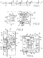
- Figure 1 shows a section of prefabricated electrical pipe according to the invention.
- Figure 2 shows on a larger scale section II - II of the pipeline.
- Figure 3 shows, in top view, the area of a bypass opening, in the clamping position of a support stud.
- FIG. 4 shows on a larger scale a view of the envelope in a section similar to that of FIG. 2.
- Figure 5 is a sectional view of the pipe with a variant of the support stud.
- FIG. 6 shows on a larger scale a detail of the device for elastic expansion and tightening of the stud of FIG. 5.
- Figure 7 is a top view of the pad.
- the prefabricated electrical pipe 10 shown in Figures 1 and 2 comprises a number of sections of the same length assembled end to end. Only a section is shown here for the sake of simplification.
- Each pipe section comprises a metal casing 11 of rectangular section, preferably square to ensure optimum rigidity, with four walls 12, 13, 14, 15, housing several bars or electrically conductive cables 16, here in the form of a sheet 17 of four conductors.
- In the wall 12 are formed at regular intervals of pitch L openings of generally rectangular shape 18, these openings having the purpose of receiving branch connectors 19 for supplying loads not shown from the conductors 16.
- the connectors 19 have an insulating body 20, a starting cable 21 and connection pins, for example in the form of elastic clamps 22 which are able to engage on stripped parts 16a of the conductors 16 to ensure the electrical connection between them and the starting cable.
- the conductors 16 are presently sheathed flexible cables, but they can also be formed by bare or sheathed metal blades or bars.
- the pipe 10 further comprises at one end a supply end 23 and at another end a closure end 24.
- Caps 25 can seal the openings 18 when they are not occupied by connectors.
- Splicing members not shown ensure the mechanical and electrical connection of the pipe sections between them, while fixing members ensure the mechanical connection of the pipe with a horizontal or vertical support wall or ensure the suspension of accessories to the pipeline.
- the envelope 11 of the pipe is produced by folding a sheet blank so as to obtain a closed contour; the folding is carried out for this purpose with longitudinal stapling at 26 of the free edges 27, 28 of the blank, that is to say folding in U with nesting of these edges.
- the watertight stapling strip 26 is provided on a wall 14 of the envelope perpendicular to the wall 12 where the bypass openings 18 are formed and it therefore increases the rigidity of the envelope.
- the axis of the pipe is denoted X-X '
- the plane of the external face of the wall 12 is denoted PP'
- the central axis of the opening 18, perpendicular to P-P ' is denoted Y-Y '.
- the rectangular section devoid of external roughness of the envelope makes it possible to obtain a clean appearance at the same time as observing good rigidity with a fairly small wall thickness.
- the ply 17 of cables 16 is carried by support pads 30 arranged at regular intervals, identical to the intervals L between the openings 18, so that the cables and their support pads form a conductive sub-assembly 31 capable of being introduced by sliding along the axis XX 'of the pipe in its tubular casing 11 with a closed contour.
- Each support stud is associated with an opening 18 and is provided with an expansion device 30a, the implementation of which, through the opening 18, allows the support to be taken and the stud held against the internal faces of the walls of the envelope.
- the stud 30 comprises an insulating body 32 provided, on the side of the opening, with a collar 33 with a chamfered centering edge 33a.
- the body 32 comprises on the side opposite the opening 18 of the legs 34 which can be applied against the internal face 15a of the wall 15 in the phase of introduction of the sub-assembly 31 inside the tubular casing and disengage from this internal face in the clamping phase of the stud.
- the body 32 are provided on the one hand for the connector a housing 35 whose bottom is subdivided into cells 35a and on the other hand, for the conductors 16, a housing 36 with respective slots 36a.
- the side walls 35b of the housing 35 serve to guide complementary shapes 37 of the connector, while the elastic plugs 22 of the latter engage on ribs 38.
- the ribs 38 brace the body 32 between the housings 35, 36 which are 'open in opposite directions; they are thinner than the parts stripped 16a of the conductors 16 which are applied against them in the direction of the opening 18.
- the body 32 of the support stud also has bearings 39 with an axis perpendicular to XX 'and Y-Y', the bearings being bordered by lugs 39a and having to receive the pins or the axis of a pivoting member 40 which constitutes in this example the expansion device 30a.
- the pivoting member 40 comprises a deformable part 42 with an elastic cam configuration located between the legs 34 and applicable against the internal face 15a of the wall 15 and, opposite this cam, rigid support legs 43; when the member 40 pivots, the branches are applicable together in the manner of a comb on the stripped rectilinear parts 16a of the conductors 16.
- the deformable part 42 pivots between an erased position (in dashes in FIG. 3) and a position d 'expansion producing the clamping of the stud (in solid lines) under the effect of the introduction of a tool through the opening 18 and its support on a hollow shape 44 to move the stud along YY' towards the opening 18, with centering of the chamfered edge 33a of the collar 33 in the opening.
- the outer edge 33a of the stud is applied against the edge of the opening while being located substantially at the plane P-P 'of the outer face 12a of the wall 12; this facilitates the fitting of the connector 19 by sliding on the wall 12 until it fits into the housing 35 of the stud.
- the support stud may have a guide finger 34a on the internal face of the wall 14 between the connection of the latter to the wall 12 and the stapling strip 26.
- the support pad On the side of the wall 13, the support pad has an elastic contact blade 50 in the form of a loop embedded at 51 on the pad; this blade has a branch 52 intended to ensure the earthing of the envelope by making contact with an area of the branch with an internal face 13a of the wall 13; the free end 53 of the branch 51 is clamped in the position for inserting the support by a heel 54 secured to the pivoting member and it is released by the heel in the clamping position (in dashes in FIG. 4).
- the electrical pipe comprises support pads which differ from those described above. Similar elements are designated by the same references.
- Each pad 30 comprises a first part 61 providing the housing 35 with its guide surfaces 35b, the collar 33 with centering edge 33a here chamfered and the guide finger 34a, as well as the slots 36a and the ribs 38 for holding the conductors.
- the stud further comprises a second part 62 which provides ribs 63 for applying the bare areas 16a of the conductors 16 to the bottom of the slots 36a; part 62 fits, snaps or is fixed in a similar way to the first part 61.
- the second part 62 of the stud has lateral openings 64 oriented obliquely to YY 'and bordered by an elastic wall 65 notched or toothed each cooperating with a tongue 66 with rack notched or toothed in a complementary manner.
- the teeth 66a of the rack tongue engage in the teeth 65a of the elastic wall, the latter is forced to come into the position indicated in dashes in FIG. 6.
- the teeth have on the one hand an oblique flank, on the other hand a flank substantially parallel to P-P '.
- the tongues 66 are rigid, but they can also be endowed with elasticity or provided with elastic means contributing to reinforce the efficiency of the elastic expansion device 30a. It is understood that the combination of the rack tongues and the elastic walls makes it possible to obtain an elastic force for tightening the stud in the pipeline.
- the stud has an elastic blade 71 for earthing the envelope.
- This blade is similar to the blade 50 and can pass from a sliding position (in dashes in FIG. 6) to an active position in which a branch 72 is applied against the face 13 of the wall 13 of the envelope (in solid lines in FIG. 5) by clearing an area 73 of the blade by means of a tool opposite a retaining shoulder 74 specific to the stud.
- a connection additive 81 can be inserted 81 to weak signal conductors 82 included in the pipeline parallel to the power conductors 16.
- weak signal conductors can be made of twisted or twisted shielded wires to avoid electromagnetic disturbances.
- the additive has plugs or knives 83 with insulation clearance for connection with the conductors 82, these plugs being integral with or electrically connected to contact blades 84 connectable to corresponding conductive parts of the connector.
- the electrical pipe described is produced in the following manner.
- the openings 18 are cut at a predetermined pitch L and the blank is folded according to longitudinal generatrices so as to obtain the envelope 11; by carrying out for this purpose a stapling of the flanges 27, 28 according to a longitudinal strip 26 which ensures a tight closure of the profile, then the exterior of the envelope is painted by any usual method.
- the sheet 17 of conductors whose zones 16a have been previously stripped is placed in the slots 36a of the bodies of molded studs 32,61 arranged at pitch L; in the example of FIGS. 3 and 4, the pivoting members are snapped into the lugs 39a of the studs and are put and maintained in the retracted position which will allow free introduction into the envelope.
- the pivoting members hold the sheet 17 applied against the bottoms of the slots 36a or close to these bottoms.
- the part 62 is fitted or snapped against the part 61 while maintaining the zones 16a of the conductors at the bottom of the slots 36a.
- the pads and cables are retained in mutual position along the axis XX 'by abutment of the sheaths 16b of the cables against the shoulders of the pads.
- each pad When each pad has thus been brought into position in front of its own bypass opening, a tool is introduced into each opening 18 to implement the expansion device.
- the member 40 is pivotally brought from its retracted position between the legs 34 to its expanded clamping position.
- the pivoting of the deformable part 42 determines the displacement of the stud in the direction of the opening 18, the centering of its chamfered edge 33a in the opening, then the elastic tightening of the cam against the internal face 15a of the wall 15.
- the comb formed by the branches 43 is applied against the bare parts 16a of the cables to hold them at the bottom of the slots, and the heel 54 releases the grounding blade 50 so that it applies against the envelope.
- the elastic effect of the pivoting member 40 or the tongues 66 makes it possible to absorb the tolerances and to make up for the clearances.
- the pipeline described can accommodate two groups of conductors instead of just one.
- a second ply 17 'situated between the legs 34 of the studs 30 associated with the first ply is illustrated in dashes in FIG. 4; the corresponding bypass openings 18 ′ are then provided in the wall 15 opposite the wall 12 and the corresponding studs (30 ′) are reversed.
- the bypass connectors can then be placed on both sides of the pipe on studs arranged alternately along the latter.
Landscapes
- Engineering & Computer Science (AREA)
- Manufacturing & Machinery (AREA)
- Connector Housings Or Holding Contact Members (AREA)
- Installation Of Indoor Wiring (AREA)
- Cable Accessories (AREA)
- Manufacturing Of Electrical Connectors (AREA)
- Particle Accelerators (AREA)
Applications Claiming Priority (2)
| Application Number | Priority Date | Filing Date | Title |
|---|---|---|---|
| FR9403251 | 1994-03-17 | ||
| FR9403251A FR2717634B1 (fr) | 1994-03-17 | 1994-03-17 | Procédé de fabrication d'une canalisation électrique et canalisation ainsi obtenue. |
Publications (2)
| Publication Number | Publication Date |
|---|---|
| EP0673089A1 true EP0673089A1 (de) | 1995-09-20 |
| EP0673089B1 EP0673089B1 (de) | 1997-09-03 |
Family
ID=9461232
Family Applications (1)
| Application Number | Title | Priority Date | Filing Date |
|---|---|---|---|
| EP95400504A Expired - Lifetime EP0673089B1 (de) | 1994-03-17 | 1995-03-09 | Kabelkanal und dessen Herstellungsverfahren |
Country Status (8)
| Country | Link |
|---|---|
| US (1) | US5676557A (de) |
| EP (1) | EP0673089B1 (de) |
| KR (1) | KR100268597B1 (de) |
| CN (1) | CN1055797C (de) |
| BR (1) | BR9501103A (de) |
| DE (1) | DE69500631T2 (de) |
| ES (1) | ES2108541T3 (de) |
| FR (1) | FR2717634B1 (de) |
Cited By (2)
| Publication number | Priority date | Publication date | Assignee | Title |
|---|---|---|---|---|
| EP0798818A1 (de) * | 1996-03-25 | 1997-10-01 | Knürr Mechanik für die Elektronik AG | Gehäuse für Mehrfachsteckdosen |
| US5967818A (en) * | 1996-12-17 | 1999-10-19 | Schneider Electric Sa | Electrical distribution duct with transmission bus |
Families Citing this family (3)
| Publication number | Priority date | Publication date | Assignee | Title |
|---|---|---|---|---|
| DE102004048414B4 (de) * | 2004-10-01 | 2006-09-07 | Fröhlich Biegetechnik GmbH & Co. KG | Elementensatz zur Erstellung von Schutzrohrleitungen |
| EP2497154B1 (de) | 2009-11-03 | 2017-04-26 | Orica Explosives Technology Pty Ltd | Stecker und verwendungsverfahren dafür |
| ES2818252T3 (es) * | 2016-08-24 | 2021-04-09 | Anord Mardix Databar Busway Ltd | Sistema de canalización de barras colectoras |
Citations (2)
| Publication number | Priority date | Publication date | Assignee | Title |
|---|---|---|---|---|
| US1809223A (en) * | 1928-05-15 | 1931-06-09 | Armen H Tashjian | Combined conduit and molding |
| GB1148184A (en) * | 1966-07-08 | 1969-04-10 | Henning Jorgensen | Improvements in or relating to ducts for enclosing electrical wiring in buildings |
Family Cites Families (3)
| Publication number | Priority date | Publication date | Assignee | Title |
|---|---|---|---|---|
| SG50306G (en) * | 1981-03-12 | 1986-05-02 | Electrak Int Ltd | Electrical distribution system |
| US4508400A (en) * | 1982-10-18 | 1985-04-02 | Rotaflex P.L.C. | Electrical supply connector for continuous outlet track |
| EP0573047A1 (de) * | 1992-06-05 | 1993-12-08 | Rhc/Spacemaster Corporation | Modulare Energieverteilungsvorrichtung |
-
1994
- 1994-03-17 FR FR9403251A patent/FR2717634B1/fr not_active Expired - Fee Related
-
1995
- 1995-03-09 ES ES95400504T patent/ES2108541T3/es not_active Expired - Lifetime
- 1995-03-09 EP EP95400504A patent/EP0673089B1/de not_active Expired - Lifetime
- 1995-03-09 DE DE69500631T patent/DE69500631T2/de not_active Expired - Lifetime
- 1995-03-16 CN CN95102874A patent/CN1055797C/zh not_active Expired - Fee Related
- 1995-03-16 US US08/404,957 patent/US5676557A/en not_active Expired - Lifetime
- 1995-03-16 BR BR9501103A patent/BR9501103A/pt not_active IP Right Cessation
- 1995-03-17 KR KR1019950005653A patent/KR100268597B1/ko not_active IP Right Cessation
Patent Citations (2)
| Publication number | Priority date | Publication date | Assignee | Title |
|---|---|---|---|---|
| US1809223A (en) * | 1928-05-15 | 1931-06-09 | Armen H Tashjian | Combined conduit and molding |
| GB1148184A (en) * | 1966-07-08 | 1969-04-10 | Henning Jorgensen | Improvements in or relating to ducts for enclosing electrical wiring in buildings |
Cited By (3)
| Publication number | Priority date | Publication date | Assignee | Title |
|---|---|---|---|---|
| EP0798818A1 (de) * | 1996-03-25 | 1997-10-01 | Knürr Mechanik für die Elektronik AG | Gehäuse für Mehrfachsteckdosen |
| US5967818A (en) * | 1996-12-17 | 1999-10-19 | Schneider Electric Sa | Electrical distribution duct with transmission bus |
| CN1065366C (zh) * | 1996-12-17 | 2001-05-02 | 施耐德电器工业公司 | 具有传输总线的配电线槽 |
Also Published As
| Publication number | Publication date |
|---|---|
| US5676557A (en) | 1997-10-14 |
| CN1116368A (zh) | 1996-02-07 |
| DE69500631T2 (de) | 1998-01-08 |
| KR950034936A (ko) | 1995-12-28 |
| EP0673089B1 (de) | 1997-09-03 |
| DE69500631D1 (de) | 1997-10-09 |
| ES2108541T3 (es) | 1997-12-16 |
| FR2717634B1 (fr) | 1996-04-26 |
| CN1055797C (zh) | 2000-08-23 |
| FR2717634A1 (fr) | 1995-09-22 |
| BR9501103A (pt) | 1995-11-14 |
| KR100268597B1 (ko) | 2000-10-16 |
Similar Documents
| Publication | Publication Date | Title |
|---|---|---|
| EP2528166B1 (de) | Erdungs-Clip und Erdungsverbund | |
| EP0247360B1 (de) | Verbindungsanordnung mit einem Schlitz für einen elektrischen Leiter und Spitze für ein entsprechendes Verbindungswerkzeug | |
| FR2630865A1 (fr) | Borne de derivation pour le raccordement d'un conducteur d'une ligne aerienne isolee a un conducteur de derivation isole | |
| FR2868884A1 (fr) | Connecteur pour cable comportant une pluralite de conducteurs torsades | |
| EP0202972B1 (de) | Schutzhülle für eine elektrische Verbindung zwischen einem Erdkabel und einer isolierten Freileitung bei Niederspannung | |
| EP0208233B1 (de) | Eingebaute Vorrichtung für elektrische Apparate zur abisolierfreien Verbindung und Verbindungswerkzeug für eine solche Vorrichtung | |
| EP0913016A1 (de) | Kabeldurchführung | |
| FR2693040A1 (fr) | Connecteur pour câbles électriques. | |
| EP0673089B1 (de) | Kabelkanal und dessen Herstellungsverfahren | |
| EP0209452B1 (de) | Mehrzweck-Steckverbinder für das Anschliessen von verschiedenen Kabeltypen oder elektrischer Leiter | |
| EP3089295B1 (de) | Elektrische verbindungsvorrichtung zur spannungsausgleichsverbindung von einem kabelrinnenabschnitt mit eines stromkabelabschnitts | |
| FR2794901A1 (fr) | Connecteur de derivation compact d'au moins un cable de derivation sur un cable principal | |
| EP0909473A1 (de) | Elektrische versorgungseinrichtung mit schutzhaube und bewegbarer stromsteckdose | |
| FR2792118A1 (fr) | Procede et dispositif d'interconnexion de bornes de raccordement | |
| FR2541049A1 (fr) | Dispositif de connexion autodenudant | |
| FR3029698A1 (fr) | Element de connexion electrique a percage de gaine isolante d'un fil electrique | |
| EP2079133B1 (de) | Verbindungsklemme mit einem Steckelement zur Aufnahme eines elektrischen Steckerstifts, Steckdose, die eine solche Klemme umfasst, und Herstellungsverfahren einer solchen Klemme | |
| FR2794902A1 (fr) | Connecteur de derivation compact d'au moins un cable de derivation de neutre sur un cable principal de neutre et mise a la terre simultanee | |
| EP2503644B1 (de) | Elektrogerät von Klemmenleiste Typ | |
| EP0744088A1 (de) | Elektrische stecker in englischer ausführung | |
| EP1928058B9 (de) | Automatische elektrische Verbindungsklemme | |
| EP1065749B1 (de) | Verbindungszusatzgerät für elektrische Apparate, ins besondere für modulare elektrische Apparate | |
| FR2803442A1 (fr) | Piece de connexion auto-denudante pouvant etre reliee a une piece de connexion voisine | |
| FR2623024A1 (fr) | Connecteur auto-denudant pour conducteur electrique isole | |
| FR2835974A1 (fr) | Dispositif de connexion a deplacement d'isolant |
Legal Events
| Date | Code | Title | Description |
|---|---|---|---|
| PUAI | Public reference made under article 153(3) epc to a published international application that has entered the european phase |
Free format text: ORIGINAL CODE: 0009012 |
|
| 17P | Request for examination filed |
Effective date: 19950317 |
|
| AK | Designated contracting states |
Kind code of ref document: A1 Designated state(s): CH DE ES GB IT LI SE |
|
| GRAG | Despatch of communication of intention to grant |
Free format text: ORIGINAL CODE: EPIDOS AGRA |
|
| GRAH | Despatch of communication of intention to grant a patent |
Free format text: ORIGINAL CODE: EPIDOS IGRA |
|
| 17Q | First examination report despatched |
Effective date: 19970212 |
|
| GRAH | Despatch of communication of intention to grant a patent |
Free format text: ORIGINAL CODE: EPIDOS IGRA |
|
| GRAA | (expected) grant |
Free format text: ORIGINAL CODE: 0009210 |
|
| AK | Designated contracting states |
Kind code of ref document: B1 Designated state(s): CH DE ES GB IT LI SE |
|
| REG | Reference to a national code |
Ref country code: CH Ref legal event code: EP |
|
| ITF | It: translation for a ep patent filed |
Owner name: JACOBACCI & PERANI S.P.A. |
|
| GBT | Gb: translation of ep patent filed (gb section 77(6)(a)/1977) |
Effective date: 19970905 |
|
| REF | Corresponds to: |
Ref document number: 69500631 Country of ref document: DE Date of ref document: 19971009 |
|
| REG | Reference to a national code |
Ref country code: ES Ref legal event code: FG2A Ref document number: 2108541 Country of ref document: ES Kind code of ref document: T3 |
|
| PLBE | No opposition filed within time limit |
Free format text: ORIGINAL CODE: 0009261 |
|
| STAA | Information on the status of an ep patent application or granted ep patent |
Free format text: STATUS: NO OPPOSITION FILED WITHIN TIME LIMIT |
|
| 26N | No opposition filed | ||
| PG25 | Lapsed in a contracting state [announced via postgrant information from national office to epo] |
Ref country code: LI Free format text: LAPSE BECAUSE OF NON-PAYMENT OF DUE FEES Effective date: 19990331 Ref country code: CH Free format text: LAPSE BECAUSE OF NON-PAYMENT OF DUE FEES Effective date: 19990331 |
|
| REG | Reference to a national code |
Ref country code: CH Ref legal event code: PL |
|
| REG | Reference to a national code |
Ref country code: GB Ref legal event code: IF02 |
|
| PGFP | Annual fee paid to national office [announced via postgrant information from national office to epo] |
Ref country code: SE Payment date: 20110218 Year of fee payment: 17 |
|
| PGFP | Annual fee paid to national office [announced via postgrant information from national office to epo] |
Ref country code: GB Payment date: 20110222 Year of fee payment: 17 Ref country code: DE Payment date: 20110202 Year of fee payment: 17 Ref country code: ES Payment date: 20110321 Year of fee payment: 17 |
|
| PGFP | Annual fee paid to national office [announced via postgrant information from national office to epo] |
Ref country code: IT Payment date: 20110330 Year of fee payment: 17 |
|
| REG | Reference to a national code |
Ref country code: DE Ref legal event code: R084 Ref document number: 69500631 Country of ref document: DE Effective date: 20111228 |
|
| REG | Reference to a national code |
Ref country code: SE Ref legal event code: EUG |
|
| PG25 | Lapsed in a contracting state [announced via postgrant information from national office to epo] |
Ref country code: SE Free format text: LAPSE BECAUSE OF NON-PAYMENT OF DUE FEES Effective date: 20120310 |
|
| GBPC | Gb: european patent ceased through non-payment of renewal fee |
Effective date: 20120309 |
|
| PG25 | Lapsed in a contracting state [announced via postgrant information from national office to epo] |
Ref country code: GB Free format text: LAPSE BECAUSE OF NON-PAYMENT OF DUE FEES Effective date: 20120309 |
|
| REG | Reference to a national code |
Ref country code: DE Ref legal event code: R119 Ref document number: 69500631 Country of ref document: DE Effective date: 20121002 |
|
| PG25 | Lapsed in a contracting state [announced via postgrant information from national office to epo] |
Ref country code: IT Free format text: LAPSE BECAUSE OF NON-PAYMENT OF DUE FEES Effective date: 20120309 |
|
| REG | Reference to a national code |
Ref country code: ES Ref legal event code: FD2A Effective date: 20130710 |
|
| PG25 | Lapsed in a contracting state [announced via postgrant information from national office to epo] |
Ref country code: ES Free format text: LAPSE BECAUSE OF NON-PAYMENT OF DUE FEES Effective date: 20120310 |
|
| PG25 | Lapsed in a contracting state [announced via postgrant information from national office to epo] |
Ref country code: DE Free format text: LAPSE BECAUSE OF NON-PAYMENT OF DUE FEES Effective date: 20121002 |