EP1928058B9 - Automatische elektrische Verbindungsklemme - Google Patents
Automatische elektrische Verbindungsklemme Download PDFInfo
- Publication number
- EP1928058B9 EP1928058B9 EP07291281A EP07291281A EP1928058B9 EP 1928058 B9 EP1928058 B9 EP 1928058B9 EP 07291281 A EP07291281 A EP 07291281A EP 07291281 A EP07291281 A EP 07291281A EP 1928058 B9 EP1928058 B9 EP 1928058B9
- Authority
- EP
- European Patent Office
- Prior art keywords
- metal body
- connection terminal
- electrical
- electrical connection
- disconnection
- Prior art date
- Legal status (The legal status is an assumption and is not a legal conclusion. Google has not performed a legal analysis and makes no representation as to the accuracy of the status listed.)
- Active
Links
- 239000002184 metal Substances 0.000 claims description 60
- 239000004020 conductor Substances 0.000 claims description 52
- 239000011810 insulating material Substances 0.000 claims description 6
- 238000003780 insertion Methods 0.000 description 3
- 230000037431 insertion Effects 0.000 description 3
- 210000002105 tongue Anatomy 0.000 description 3
- 238000002513 implantation Methods 0.000 description 2
- 210000003323 beak Anatomy 0.000 description 1
- 210000000078 claw Anatomy 0.000 description 1
- 230000009977 dual effect Effects 0.000 description 1
- 230000005611 electricity Effects 0.000 description 1
- 238000003032 molecular docking Methods 0.000 description 1
- 230000007935 neutral effect Effects 0.000 description 1
- 230000002093 peripheral effect Effects 0.000 description 1
Images


Classifications
-
- H—ELECTRICITY
- H01—ELECTRIC ELEMENTS
- H01R—ELECTRICALLY-CONDUCTIVE CONNECTIONS; STRUCTURAL ASSOCIATIONS OF A PLURALITY OF MUTUALLY-INSULATED ELECTRICAL CONNECTING ELEMENTS; COUPLING DEVICES; CURRENT COLLECTORS
- H01R4/00—Electrically-conductive connections between two or more conductive members in direct contact, i.e. touching one another; Means for effecting or maintaining such contact; Electrically-conductive connections having two or more spaced connecting locations for conductors and using contact members penetrating insulation
- H01R4/28—Clamped connections, spring connections
- H01R4/48—Clamped connections, spring connections utilising a spring, clip, or other resilient member
- H01R4/4809—Clamped connections, spring connections utilising a spring, clip, or other resilient member using a leaf spring to bias the conductor toward the busbar
- H01R4/4828—Spring-activating arrangements mounted on or integrally formed with the spring housing
- H01R4/48365—Spring-activating arrangements mounted on or integrally formed with the spring housing with integral release means
Definitions
- the present invention generally relates to electrical connectors.
- an automatic electrical connection terminal comprising a metal body, elastic means of pressure of an electrical conductor against said metal body, a conduit for engagement of said electrical conductor between said metal body and said elastic pressure means and a disconnect lever adapted to bear on said elastic pressure means to move them away from said metal body.
- an electrical connector comprising a base of insulating material provided internally with at least one housing for receiving such a connection terminal.
- the relative arrangement of the disconnection lever and the electrical connection terminal engagement duct of the aforementioned type is such that the automatic electrical connection terminal occupies a relatively large volume of space requirement.
- the present invention proposes a connection terminal of small height.
- connection terminal according to the features of claim 1.
- the passage of the engagement conduit through the disconnect lever can significantly reduce the height of the connection terminal.
- the terminal is therefore more easily habitable.
- a first advantageous characteristic of the invention is mentioned in claim 2.
- the electrical conductor does not interfere with accessibility to the support portion.
- the electrical conductor opening out of the terminal on the side where the support portion is, the movement of the disconnect lever to disconnect the electrical conductor is not hindered by the presence of the latter.
- the metal body has a symmetrical shape with respect to an axis and in which the first and second disconnect levers are arranged in staggered rows and symmetrically with respect to this axis of symmetry.
- the staggered arrangement of the two disconnect levers greatly reduces its length compared to a conventional arrangement in which the levers would be arranged in the extension of one another.
- the overall thickness of a docking base of the connection terminal is therefore reduced.
- the invention also relates to an electrical connector according to claim 10.
- a first advantageous characteristic of the electrical connector according to the invention is mentioned in claim 11.
- the arrangement of the guide ducts and engagement provides a relative tolerance on the stripping length of the electrical conductor, knowing that the stripped portion will in any case housed in an insulating portion inaccessible to the user.
- the guide duct accessible from the user side makes it possible to connect the terminal to a first electrical equipment.
- This face has only one conduit which prevents the user to connect several electrical devices on the same terminal.
- the two guide ducts accessible from the installer side they allow the installer, on the one hand, to supply the connection terminal via an electrical conductor of an electrical supply network, and, on the other hand, to transfer this power supply to another electrical connector connected to a second electrical equipment.
- This simple electrical connection terminal 10 comprises a metal body 20 and elastic pressure means 16 of an electrical conductor 1 against said metal body 20 for electrically connecting the metal body with the electrical conductor 1.
- the electrical conductor 1 comprises a conductive metal core 2 and an insulating sheath 3. Its end inserted between the elastic pressure means 16 and the metal body 20 is stripped of insulating sheath.
- the metal body 20 is a stamped plate in the form of a staircase with three steps (lower, central and upper) interconnected by transverse sections, including a lower section which connects the lower step with the central step, and an upper section which connects the central step with the upper step.
- the metal body 20 has in particular a symmetrical shape with respect to an axis of symmetry A1 normal to the section plane of the figure 1 .
- each of the two transverse panels is pierced by a window 21.
- the edge of each of these windows 21 which is adjacent to the central step is provided with a tongue formed during the step stamping.
- the tabs protrude the sides of the metal body 20 in the extension of the central step.
- the elastic pressure means are in turn constituted by a U-shaped prestressed metal leaf spring 16.
- One of the branches of this U, the lower branch, is immobilized with respect to the lower step of the metal body 20 while the end of the other of the branches, the upper branch, passes through the window 21 of the lower pan of the metal body 20.
- the free end of this branch is configured to form a clamp.
- the lower branch is cut longitudinally into three parts, including a central portion 17A which bears on the upper face of the lower step of the metal body 20, and two lateral tongues 17B which bear against the underside of the lower step of the metal body 20 (see figure 2 ).
- the end edge of this branch could be shaped into a beak so as to be able to hook on the lower edge of the window 21 of the lower pan of the metal body 20 .
- the insertion of the stripped end of the electrical conductor 1 in the window 21 causes the removal of the upper branch of the spring blade 21 relative to the central step of the metal body 20.
- the electrical conductor 1 is then clamped between the metal body 20 and the spring blade 16 which, being both conductors, are thus adapted to conduct together the electric current delivered by the electrical conductor 1.
- the single electrical connection terminal 10 further comprises a disconnection lever 11 adapted to bear on the upper branch of the spring blade 16 to move it away from the central step of the metal body 20.
- the disconnecting lever 11 has an elongated shape and is made in one piece of insulating material.
- One of its ends comprises, on the side of its upper face 12A, a bearing portion 13 accessible to a finger of a user so that it can operate the lever.
- This bearing portion is inclined and is offset in height relative to the remainder of the upper face 12A of the disconnection lever 11.
- the other end of the disconnection lever 11 has two parallel arms 12C ( figure 3B ) which extend side by side in the extension of the lever and whose ends are integral with a shaft 15 A2 axis transverse to the axes of the parallel arms 12C.
- This shaft 15 has a length such that it protrudes on either side of the two parallel arms 12C of the disconnection lever 11. These projecting ends of the parallel arms 12C are adapted to be pivotally mounted in corresponding housings, if although the disconnect lever 11 can pivot about the axis A2, called the axis of rotation.
- the shaft 15 further comprises at mid-height, on its cylindrical side face, a radial tooth 18 in edge to guide the pivoting of the disconnection lever 11. Its operation will be described in more detail later.
- the axis of rotation A2 of the disconnection lever 11 is arranged parallel to the axis of symmetry A1 of the metal body 20, close to the upper step of the latter.
- the disconnection lever 11 is then disposed on the side of one of the faces of the metal body 20 so that its lower face 12B bears against the upper branch of the spring blade 16 (see FIG. figure 3A ).
- the support of a finger of the user on the bearing portion 13 of the disconnection lever 11 thus causes, on the one hand, its pivoting about the axis of rotation A2, and, on the other hand, the deformation of the leaf spring 16.
- the upper branch of the spring blade 16 then moves away from the stripped end of the electrical conductor 1 so that the latter being no longer pinched, the electrical conductor 1 can be extracted from the electrical connection terminal 10.
- the single connection terminal 10 comprises an engagement duct 14 of the electrical conductor 1 which passes through the disconnection lever 11.
- the engagement duct 14 passes obliquely through the disconnection lever 11 to open, on one side, opposite the window 21 of the lower pan of the metal body 20, and, on the other, on the upper face 12A of the disconnection lever 11, near its bearing portion 13.
- the engagement duct 14 further has, in the direction of the window 21, a narrowing section which facilitates the insertion of the electrical conductor 1 on the side of the upper face 12A of the lever and which prevents the insulating sheath 3 of the electrical conductor 1 to open beyond the lower face 12B of the disconnect lever, at the risk of electrically isolating the electrical conductor 1 of the metal body 20.
- the position of the outlet of the engagement duct on the upper face 12A of the disconnection lever 11, above the support portion 13, is such that, on the one hand, the electrical conductor 1 does not interfere with accessibility to the support portion 13 of the disconnect lever 11, and, secondly, it does not impede the pivoting movement of the disconnect lever.
- the electrical connection terminal 10 may comprise a second engagement duct 19 of a second electrical conductor 4, which passes through the disconnection lever 11 parallel to the first engagement duct 14.
- the metal body 20 comprises on each of its lower and upper panels two windows 21 arranged side by side and each intended to be traversed by one of the stripped ends of the electrical conductors 1, 4 (see figure 1 ).
- the spring blade 16 has a width such that it can simultaneously pinch the two stripped ends of the electrical conductors 1, 4 against the metal body 20.
- the upper branch of the leaf spring 16 is divided into two parts by a longitudinal slot.
- each of the two parts of the upper branch of the spring blade 16 adapts to the diameter of the corresponding electrical conductor to hold it firmly in place.
- the two electrical conductors 1, 4 can thus be connected to the same electrical potential.
- This double electrical connection terminal 30 comprises, in addition to the elements of the simple terminal described above, second means pressure elastics 36 adapted to clamp the stripped end of one or two other electrical conductors 5, 6 against said metal body 20 of the terminal.
- These second elastic pressure means comprise a second metal leaf spring 36 which is identical to the first leaf spring 16 and which is arranged symmetrically to this first leaf spring 16 relative to the axis of symmetry A1 of the metal body 20.
- the double electrical connection terminal 30 further comprises a second disconnection lever 31, identical to the first disconnect lever 11, which is adapted to bear on the second spring blade 36 to move it away from said metal body 20 in order to disengage the conductors possibly pinched between the second spring blade 36 and the metal body 20.
- the second disconnection lever 31 also comprises two parallel arms (not referenced on the Figures 4 and 5 ) integral with a shaft 35 pivoting axis A3 called axis of rotation.
- the shaft 35 comprises, like the shaft 15 of the first disconnection lever 11, a radial tooth 38 shaped to pivotally guide the disconnection lever 31.
- This second disconnection lever 31 is crossed by two engagement ducts 34, 39 for inserting these other electrical conductors 5, 6 between the metal body 20 and the second spring blade 36.
- These engagement ducts 34, 39 of FIG. oblique axes open on the upper face 32A of the second disconnection lever 31, offset in height relative to the bearing portion 33 of the second disconnect lever 31.
- the first and second disconnect levers 11, 31 of the electrical connection terminal 30 are arranged on either side of the metal body 20 so that their support portions 13, 33 are positioned head to tail.
- first and second disconnect levers 11, 31 are arranged in staggered rows and symmetrically with respect to the axis of symmetry A1 of the metal body 20, so that their respective axes of rotation A2, A3 are parallel.
- the electrical connection terminal 30 makes it possible to connect four electrical conductors 1, 4, 5, 6 to the same electrical potential.
- two electrical conductors 1, 4 are inserted into the engagement ducts 14, 19 of the first disconnection lever 11 and two electrical conductors 5, 6 are inserted into the engagement ducts 34, 39 of the second disconnection lever. 31, so that the stripped ends of the four electrical conductors are brought into contact with the metal body 20 of the terminal by pressing the spring blades 16, 36 metal.
- the double electrical connection terminal 30 is housed, together with other electrical connection terminals, in a base 41 of an electrical connector 40.
- the base 41 is of parallelepipedal shape and is made of insulating material. It has four side walls which border, on one side, a front wall 47 substantially square, and on the other, a rear wall 48 also square.
- this base 41 has inner walls which define in particular four receiving housings 44 of four double electrical connection terminals.
- the electrical connector 40 makes it possible to electrically connect at least one electrical equipment to the local electrical network.
- each of the four connection terminals connects a pole of the electrical network to an electrical input of the apparatus.
- a first of the connection terminals is intended to be connected to the phase of the electrical network, a second to neutral, a third to earth and a fourth to an arrival of a pilot electrical wire for electric convector.
- the base 41 is made in two portions 45, 46 assembled by snapping, a front portion 45 which comprises the front wall 47 and a portion of each of the four side walls of the base 41, and a rear portion 46 which comprises the wall 48 and the other portion of each of the four side walls of the base 41.
- These two parts 45, 46 each comprise a portion of the inner walls of the base. They come in concordance during the assembly of the base.
- the junction between the two parts of the inner walls defines small openings in which the ends of the shafts of the disconnecting levers electrical connection terminals are inserted, so that these disconnect lever can rotate about their respective axes of rotation A2, A3.
- Each receiving housing 44 of the base 41 has a tubular shape of square section which extends from the front wall 47 of the base 41 to its rear wall 48.
- Each receiving housing 44 opens on the front and rear walls 47, 48 of the base 41 through openings 49, 50 through which only the bearing portions 13, 33 of the disconnecting levers 11, 31 protrude. These openings are therefore made in the extension of the receiving housing 44 and have a shape enabling them to precisely border the disconnecting levers 11, 31.
- the front and rear walls 47, 48 of the base 41 furthermore comprise slots (not visible in the figures) which extend from the openings 49, 50 and which allow the disconnecting levers 11, 31 to pivot without abutting against the edges of these openings.
- the rear faces of the disconnect levers 11, 31 are hollowed so that their flanges form projecting ribs adapted to slide along the slots.
- the inner walls of the base 41 also comprise longitudinal slots into which the radial teeth 18, 38 of the shafts 15, 35 of the disconnecting levers 11, 31 fit. The cooperation of these slots and of these radial teeth 18, 38 makes it possible to guide the disconnect levers 11, 31 during their pivoting.
- the openings 49, 50 of the front and rear walls 47, 48 being precisely fitted on the disconnecting levers 11, 31, they block the insertion of electrical conductors into the engagement ducts 14, 19, 34, 39 of the disconnecting levers 11, 31.
- the front and rear walls 47, 48 of the base 41 are hollowed with guide ducts 42, 43 which are arranged adjacent the openings 49, 50 of the front and rear walls 47, 48.
- Each guide duct passes through the corresponding wall of the base 41 along an oblique axis, in the extension of one of the engagement ducts of the disconnection lever which projects from this wall.
- the guide ducts 42, 43 guide the electrical conductors to the engagement ducts 14, 19, 34, 39 which pass through the disconnect levers 11, 31.
- the front wall 47 of the base which is intended to be accessible to a user without special training in electricity, comprises a single guide duct 42 by electrical connection terminal 30.
- This single guide duct 42 opens opposite one of the two engagement ducts 14, 19 of the first disconnect lever 11 associated.
- the user can connect an electrical equipment to the electrical connector 40.
- the rear wall 48 of the base which is intended to be accessible to an installer, comprises two guide ducts 42 by double electrical connection terminal 30. These two guide ducts open opposite the two engagement ducts 34, 39 of the second associated disconnection lever 31.
- the installer can not only connect the electrical connector 40 to the local electrical network, but it can also transplant this connection to power another electrical connector.
- the base 41 further comprises a cable clamp 52 well known to those skilled in the art, which comprises a flange fixed by two screws 53, 54 to the front wall 47 of the base 41.
- This clamp 52 can hold firmly the electrical conductors 1, 4 in place, so that a force exerted on one of the conductors does not pull it from the electrical connection terminal in which it is inserted.
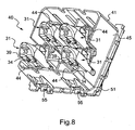
- the base 41 is intended to be installed in a recess box (not shown for the legibility of the figures) housed in a housing 101 of a wall wall 100.
- This housing 101 has a lateral opening 102 through which the electrical conductors open 5, 6 to be connected to the electrical connection terminals 30, on the rear face of the base 41.
- an apparatus support 90 fixed on the flush-mounting box and bearing against the front face of the wall wall 100.
- the base 41 is mounted on the equipment support 90 For this purpose, it is bordered along its side walls, near its front wall, with a peripheral rim 51 ( figure 8 ).
- two of its walls side include two latching claws 55 cooperating with hooking ribs of the equipment support 90.
Claims (14)
- Automatische elektrische Anschlussklemme (10, 30) mit:einem Metallstück (20),elastischen Druckmitteln (16, 36), die einen elektrischen Leiter (1, 5) gegen das Metallstück (20) drücken,einem Einführkanal (14, 34) für den elektrischen Leiter (1, 5) zwischen dem Metallstück (20) und den elastischen Druckmitteln (16, 36), undeinem Trennhebel (11, 31), der sich dazu eignet, sich auf den elastischen Druckmitteln (16, 36) abzustützen, um sie vom Metallstück (20) fernzuhalten,dadurch gekennzeichnet, dass der Einführkanal (14, 34) den Trennhebel (11, 31) durchquert und dadurch, dass zweite elastische Druckmittel (36) vorgesehen sind, die einen anderen elektrischen Leiter (5, 6) gegen das Metallstück (20) drücken, sowie ein zweiter Trennhebel (31), der sich dazu eignet, sich auf den zweiten elastischen Druckmitteln (36) abzustützen, um sie vom Metallstück (20) fernzuhalten, wobei der zweite Trennhebel (31) zwischen dem Metallstück (20) und den zweiten elastischen Druckmitteln (36) von einem Einführkanal (34, 39) des elektrischen Leiters (5, 6) durchquert wird.
- Elektrische Anschlussklemme (10, 30) nach vorausgehendem Anspruch, bei der der Einführkanal (14, 34) den Trennhebel (11, 31) schräg durchquert, um auf der einen Seite gegenüber der Einklemmzone der elastischen Druckmittel (16, 36) auf dem Metallstück (20) und auf der anderen Seite auf einer Seite des Trennhebels (11, 31) zu münden, die einen für den Anwender zugänglichen Auflagebereich (13, 31) umfasst, der in Bezug zur Mündung des Einführkanals (14, 34) auf dieser Seite in der Höhe versetzt ist.
- Elektrische Anschlussklemme (10, 30) nach einem der vorausgehenden Ansprüche, die einen zweiten Einführkanal (19, 39) umfasst, der den Trennhebel (11, 31) parallel zum ersten Einführkanal (14, 34) durchquert, um das Einführen eines zweiten elektrischen Leiters (4, 6) zwischen dem Metallstück (20) und den elastischen Druckmitteln (16, 36) zu ermöglichen.
- Elektrische Anschlussklemme (10, 30) nach einem der vorausgehenden Ansprüche, bei der der erste und zweite Trennhebel (11, 31) identisch und auf beiden Seiten des Metallstücks (20) angeordnet sind.
- Elektrische Anschlussklemme (10; 30) nach vorausgehendem Anspruch, bei der das Metallstück eine in Bezug zu einer Achse (A1) symmetrische Form aufweist und bei der der erste und zweite Trennhebel (11, 31) in Bezug zu dieser Symmetrieachse (A1) schachbrettartig versetzt und symmetrisch angeordnet sind.
- Elektrische Anschlussklemme (10, 30) nach einem der vorausgehenden Ansprüche, bei der jeder Trennhebel (11, 31) um eine Rotationsachse (A2, A3) drehbar montiert ist.
- Elektrische Anschlussklemme (10, 30) nach einem der vorausgehenden Ansprüche, bei der jedes der elastischen Druckmittel (16, 36) eine vorgespannte U-förmige Klemmfeder aus Metall umfasst, wobei ein Arm des Us in Bezug zum Metallstück (20) blockiert ist und der andere Arm gegen das Metallstück (20) gedrückt wird.
- Elektrische Anschlussklemme (10, 30) nach einem der vorausgehenden Ansprüche, bei der jeder Trennhebel (11, 31) aus einem einzigen Teil und aus einem isolierenden Material hergestellt ist.
- Elektrische Anschlussklemme (10, 30) nach einem der vorausgehenden Ansprüche, bei der das Metallstück (20) in Form einer treppenförmig gestanzten Platte vorliegt.
- Elektrischer Anschlussstecker (40), der zum einen einen Sockel (41) aus einem isolierenden Material umfasst, der im Innenraum mit mindestens einer auf einer der Seiten (47, 48) des Sockels (41) durch eine Öffnung (49, 50) mündende Aufnahme (44) versehen ist, und zum anderen eine Anschlussklemme (10, 30) nach einem der vorausgehenden Ansprüche, die derart in der Aufnahme (44) untergebracht ist, dass lediglich ein Auflagebereich (13, 33) ihres Trennhebels (11, 31) über die Öffnung (49, 50) hervorsteht.
- Elektrischer Anschlussstecker (40) nach vorausgehendem Anspruch, bei dem der Sockel (41) mindestens einen Führungskanal (42, 43) umfasst, der neben der Öffnung (49, 50) in die Seite (47, 48) des Sockels (41) mündet, um einen elektrischen Leiter (1, 4, 5, 6) zu einem Einführkanal (14, 19, 34, 39) zu führen, der den Trennhebel (11, 31) durchquert.
- Elektrischer Anschlussstecker (40) nach einem der zwei vorausgehenden Ansprüche mit einer elektrischen Anschlussklemme (30) nach Anspruch 2, bei dem die Aufnahme (44) in zwei entgegengesetzte Seiten (47, 48) des Sockels (41) mündet, wobei eine Seite (47) für einen Anwender und eine Seite (48) für einen Installateur zugänglich ist, und bei dem nur der Auflagebereich (13) des ersten Trennhebels (11) auf der dem Anwender zugänglichen Seite (47) übersteht und nur der Auflagebereich (33) des zweiten Trennhebels (31) auf der dem Installateur zugänglichen Seite (48) übersteht.
- Elektrischer Anschlussstecker (40) nach den zwei vorausgehenden Ansprüchen mit einer elektrischen Anschlussklemme (30) nach Anspruch 3, bei dem der Sockel (41) zwei Führungskanäle (43) umfasst, die auf der dem Installateur (48) zugänglichen Seite münden, um zwei elektrische Leiter (5,6) zu den zwei Einführkanälen (34,39) zu führen, die den zweiten Trennhebel (31) durchqueren, sowie einen einzigen Führungskanal (42), der auf der dem Anwender (47) zugänglichen Seite mündet, um einen elektrischen Leiter (1, 4) zu einem der Einführkanäle (14, 19) zu führen, die den ersten Trennhebel (11) durchqueren.
- Elektrischer Anschlussstecker (40) nach einem der Ansprüche 10 bis 11, bei dem der Sockel (41) zwei durch Einrasten verbundene Teile (45, 46) umfasst.
Applications Claiming Priority (1)
| Application Number | Priority Date | Filing Date | Title |
|---|---|---|---|
| FR0610406A FR2909227B1 (fr) | 2006-11-28 | 2006-11-28 | Borne de connexion electrique automatique. |
Publications (3)
| Publication Number | Publication Date |
|---|---|
| EP1928058A1 EP1928058A1 (de) | 2008-06-04 |
| EP1928058B1 EP1928058B1 (de) | 2012-08-15 |
| EP1928058B9 true EP1928058B9 (de) | 2012-11-14 |
Family
ID=38093406
Family Applications (1)
| Application Number | Title | Priority Date | Filing Date |
|---|---|---|---|
| EP07291281A Active EP1928058B9 (de) | 2006-11-28 | 2007-10-22 | Automatische elektrische Verbindungsklemme |
Country Status (3)
| Country | Link |
|---|---|
| EP (1) | EP1928058B9 (de) |
| ES (1) | ES2389312T3 (de) |
| FR (1) | FR2909227B1 (de) |
Families Citing this family (2)
| Publication number | Priority date | Publication date | Assignee | Title |
|---|---|---|---|---|
| WO2010034430A1 (de) * | 2008-09-29 | 2010-04-01 | Abb Ag | Installationsschaltgerät mit einem schraubenlosen klemmanschluss |
| ES1069768Y (es) * | 2008-10-07 | 2009-08-21 | Simon Sa | Tecla de embornado rapido para mecanismos electricos con enclavamiento de seguridad |
Family Cites Families (7)
| Publication number | Priority date | Publication date | Assignee | Title |
|---|---|---|---|---|
| DE8424056U1 (de) * | 1984-08-14 | 1984-11-15 | Gira Elektrotechnische Industrie Gustav Giersiepen, 5608 Radevormwald | Schraubenlose Anschlußklemme für elektrische Geräte, insbesondere für Installationsgeräte |
| US4768976A (en) * | 1987-08-06 | 1988-09-06 | Bruno Gelati | Electrical connector |
| FR2754640B1 (fr) * | 1996-10-16 | 1998-12-18 | Legrand Sa | Borne de connexion automatique, et appareil electrique equipe d'une telle borne de connexion |
| US6716070B2 (en) * | 2001-10-06 | 2004-04-06 | Cardio Connector Corp. | Biomedical patient electrode clasp with automatic stud lock |
| FR2873859B1 (fr) * | 2004-07-30 | 2006-12-08 | Legrand Sa | Appareil electrique comportant une borne a connexion automatique |
| EP1909359A3 (de) * | 2006-10-06 | 2008-07-16 | ABB PATENT GmbH | Klemmanschluss, Anschlussklemmenanordnung und Installationsschaltgerät |
| EP1914839B1 (de) * | 2006-10-21 | 2010-12-08 | Abb Ag | Installationsschaltgerät |
-
2006
- 2006-11-28 FR FR0610406A patent/FR2909227B1/fr not_active Expired - Fee Related
-
2007
- 2007-10-22 EP EP07291281A patent/EP1928058B9/de active Active
- 2007-10-22 ES ES07291281T patent/ES2389312T3/es active Active
Also Published As
| Publication number | Publication date |
|---|---|
| FR2909227B1 (fr) | 2009-04-03 |
| EP1928058B1 (de) | 2012-08-15 |
| EP1928058A1 (de) | 2008-06-04 |
| ES2389312T3 (es) | 2012-10-25 |
| FR2909227A1 (fr) | 2008-05-30 |
Similar Documents
| Publication | Publication Date | Title |
|---|---|---|
| WO2014096674A1 (fr) | Boite électrique pour appareillage électrique | |
| FR2954604A1 (fr) | Borne de connexion electrique automatique et appareillage electrique comportant une telle borne | |
| EP1928058B1 (de) | Automatische elektrische Verbindungsklemme | |
| EP3089295B1 (de) | Elektrische verbindungsvorrichtung zur spannungsausgleichsverbindung von einem kabelrinnenabschnitt mit eines stromkabelabschnitts | |
| EP0209452B1 (de) | Mehrzweck-Steckverbinder für das Anschliessen von verschiedenen Kabeltypen oder elektrischer Leiter | |
| EP3227966B1 (de) | Elektrisches verbindungselement, das einen stromdrahtisolierungsmantel penetriert | |
| FR3073681A1 (fr) | Dispositif de connexion et deconnexion d'un cable electrique | |
| EP1916742A1 (de) | Elektrische Steckdose | |
| EP2992570B1 (de) | Elektrisches gehäuse mit einem verbindungshebel | |
| EP1968160B1 (de) | Elektrischer Apparat mit automatischen elektrischen Prioritätsanschlüssen | |
| FR2963488A1 (fr) | Embout multipolaire de connexion electrique | |
| EP2079133B1 (de) | Verbindungsklemme mit einem Steckelement zur Aufnahme eines elektrischen Steckerstifts, Steckdose, die eine solche Klemme umfasst, und Herstellungsverfahren einer solchen Klemme | |
| EP2166620B1 (de) | Elektrischer Anschluss | |
| EP1865579B1 (de) | Selbstabisolierende Verbindungsanschluss und elektrisches Gerät mit einem solchen Anschluss | |
| EP1881561B1 (de) | Automatischer Anschluss mit einer Leitwand und elektrisches Gerät mit einem solchen Anschluss | |
| EP3255732B1 (de) | Elektrische verbindungsklemme, die einen verbindungshebel umfasst, und entsprechende elektrische geräte | |
| FR2691846A1 (fr) | Prise de courant électrique à contact auto-dénudant. | |
| FR3020506A1 (fr) | Borne de connexion electrique multi-conducteurs | |
| EP1944833B1 (de) | Verbindungsklemme mit Doppelgabel | |
| FR2815775A1 (fr) | Prise de courants faibles du type "modular jack" comprenant un peigne amovible de positionnement des fils electriques au-dessus des contacts metalliques autodenudants | |
| EP2068411A1 (de) | Elektrische Einbau-Ausrüstung mit Schnellanschluss | |
| FR2835974A1 (fr) | Dispositif de connexion a deplacement d'isolant | |
| WO2014096677A1 (fr) | Module d'appareillage electrique | |
| EP2843766A1 (de) | Elektrische Vorrichtung, die einen gedruckten elektrischen Schaltkreis auf einer Halterungsplatte und eine elektrische Anschlussklemme umfasst | |
| FR3029697A1 (fr) | Element de connexion electrique a percage de gaine isolante comprenant un ressort, borne de connexion electrique et appareillage electrique associes |
Legal Events
| Date | Code | Title | Description |
|---|---|---|---|
| PUAI | Public reference made under article 153(3) epc to a published international application that has entered the european phase |
Free format text: ORIGINAL CODE: 0009012 |
|
| AK | Designated contracting states |
Kind code of ref document: A1 Designated state(s): AT BE BG CH CY CZ DE DK EE ES FI FR GB GR HU IE IS IT LI LT LU LV MC MT NL PL PT RO SE SI SK TR |
|
| AX | Request for extension of the european patent |
Extension state: AL BA HR MK RS |
|
| 17P | Request for examination filed |
Effective date: 20080905 |
|
| AKX | Designation fees paid |
Designated state(s): AT BE BG CH CY CZ DE DK EE ES FI FR GB GR HU IE IS IT LI LT LU LV MC MT NL PL PT RO SE SI SK TR |
|
| 17Q | First examination report despatched |
Effective date: 20091106 |
|
| GRAP | Despatch of communication of intention to grant a patent |
Free format text: ORIGINAL CODE: EPIDOSNIGR1 |
|
| GRAS | Grant fee paid |
Free format text: ORIGINAL CODE: EPIDOSNIGR3 |
|
| GRAA | (expected) grant |
Free format text: ORIGINAL CODE: 0009210 |
|
| AK | Designated contracting states |
Kind code of ref document: B1 Designated state(s): AT BE BG CH CY CZ DE DK EE ES FI FR GB GR HU IE IS IT LI LT LU LV MC MT NL PL PT RO SE SI SK TR |
|
| REG | Reference to a national code |
Ref country code: GB Ref legal event code: FG4D Free format text: NOT ENGLISH Ref country code: CH Ref legal event code: EP Ref country code: AT Ref legal event code: REF Ref document number: 571235 Country of ref document: AT Kind code of ref document: T Effective date: 20120815 |
|
| REG | Reference to a national code |
Ref country code: IE Ref legal event code: FG4D Free format text: LANGUAGE OF EP DOCUMENT: FRENCH |
|
| REG | Reference to a national code |
Ref country code: DE Ref legal event code: R096 Ref document number: 602007024737 Country of ref document: DE Effective date: 20121011 |
|
| REG | Reference to a national code |
Ref country code: ES Ref legal event code: FG2A Ref document number: 2389312 Country of ref document: ES Kind code of ref document: T3 Effective date: 20121025 |
|
| REG | Reference to a national code |
Ref country code: NL Ref legal event code: VDEP Effective date: 20120815 |
|
| REG | Reference to a national code |
Ref country code: AT Ref legal event code: MK05 Ref document number: 571235 Country of ref document: AT Kind code of ref document: T Effective date: 20120815 |
|
| PG25 | Lapsed in a contracting state [announced via postgrant information from national office to epo] |
Ref country code: FI Free format text: LAPSE BECAUSE OF FAILURE TO SUBMIT A TRANSLATION OF THE DESCRIPTION OR TO PAY THE FEE WITHIN THE PRESCRIBED TIME-LIMIT Effective date: 20120815 Ref country code: LT Free format text: LAPSE BECAUSE OF FAILURE TO SUBMIT A TRANSLATION OF THE DESCRIPTION OR TO PAY THE FEE WITHIN THE PRESCRIBED TIME-LIMIT Effective date: 20120815 Ref country code: CY Free format text: LAPSE BECAUSE OF FAILURE TO SUBMIT A TRANSLATION OF THE DESCRIPTION OR TO PAY THE FEE WITHIN THE PRESCRIBED TIME-LIMIT Effective date: 20120815 Ref country code: IS Free format text: LAPSE BECAUSE OF FAILURE TO SUBMIT A TRANSLATION OF THE DESCRIPTION OR TO PAY THE FEE WITHIN THE PRESCRIBED TIME-LIMIT Effective date: 20121215 Ref country code: AT Free format text: LAPSE BECAUSE OF FAILURE TO SUBMIT A TRANSLATION OF THE DESCRIPTION OR TO PAY THE FEE WITHIN THE PRESCRIBED TIME-LIMIT Effective date: 20120815 |
|
| PG25 | Lapsed in a contracting state [announced via postgrant information from national office to epo] |
Ref country code: LV Free format text: LAPSE BECAUSE OF FAILURE TO SUBMIT A TRANSLATION OF THE DESCRIPTION OR TO PAY THE FEE WITHIN THE PRESCRIBED TIME-LIMIT Effective date: 20120815 Ref country code: SE Free format text: LAPSE BECAUSE OF FAILURE TO SUBMIT A TRANSLATION OF THE DESCRIPTION OR TO PAY THE FEE WITHIN THE PRESCRIBED TIME-LIMIT Effective date: 20120815 Ref country code: SI Free format text: LAPSE BECAUSE OF FAILURE TO SUBMIT A TRANSLATION OF THE DESCRIPTION OR TO PAY THE FEE WITHIN THE PRESCRIBED TIME-LIMIT Effective date: 20120815 Ref country code: GR Free format text: LAPSE BECAUSE OF FAILURE TO SUBMIT A TRANSLATION OF THE DESCRIPTION OR TO PAY THE FEE WITHIN THE PRESCRIBED TIME-LIMIT Effective date: 20121116 Ref country code: PT Free format text: LAPSE BECAUSE OF FAILURE TO SUBMIT A TRANSLATION OF THE DESCRIPTION OR TO PAY THE FEE WITHIN THE PRESCRIBED TIME-LIMIT Effective date: 20121217 Ref country code: PL Free format text: LAPSE BECAUSE OF FAILURE TO SUBMIT A TRANSLATION OF THE DESCRIPTION OR TO PAY THE FEE WITHIN THE PRESCRIBED TIME-LIMIT Effective date: 20120815 |
|
| PG25 | Lapsed in a contracting state [announced via postgrant information from national office to epo] |
Ref country code: NL Free format text: LAPSE BECAUSE OF FAILURE TO SUBMIT A TRANSLATION OF THE DESCRIPTION OR TO PAY THE FEE WITHIN THE PRESCRIBED TIME-LIMIT Effective date: 20120815 |
|
| BERE | Be: lapsed |
Owner name: LEGRAND SNC Effective date: 20121031 Owner name: LEGRAND FRANCE Effective date: 20121031 |
|
| PG25 | Lapsed in a contracting state [announced via postgrant information from national office to epo] |
Ref country code: EE Free format text: LAPSE BECAUSE OF FAILURE TO SUBMIT A TRANSLATION OF THE DESCRIPTION OR TO PAY THE FEE WITHIN THE PRESCRIBED TIME-LIMIT Effective date: 20120815 Ref country code: DK Free format text: LAPSE BECAUSE OF FAILURE TO SUBMIT A TRANSLATION OF THE DESCRIPTION OR TO PAY THE FEE WITHIN THE PRESCRIBED TIME-LIMIT Effective date: 20120815 Ref country code: CZ Free format text: LAPSE BECAUSE OF FAILURE TO SUBMIT A TRANSLATION OF THE DESCRIPTION OR TO PAY THE FEE WITHIN THE PRESCRIBED TIME-LIMIT Effective date: 20120815 Ref country code: RO Free format text: LAPSE BECAUSE OF FAILURE TO SUBMIT A TRANSLATION OF THE DESCRIPTION OR TO PAY THE FEE WITHIN THE PRESCRIBED TIME-LIMIT Effective date: 20120815 |
|
| PG25 | Lapsed in a contracting state [announced via postgrant information from national office to epo] |
Ref country code: IT Free format text: LAPSE BECAUSE OF FAILURE TO SUBMIT A TRANSLATION OF THE DESCRIPTION OR TO PAY THE FEE WITHIN THE PRESCRIBED TIME-LIMIT Effective date: 20120815 Ref country code: MC Free format text: LAPSE BECAUSE OF NON-PAYMENT OF DUE FEES Effective date: 20121031 Ref country code: SK Free format text: LAPSE BECAUSE OF FAILURE TO SUBMIT A TRANSLATION OF THE DESCRIPTION OR TO PAY THE FEE WITHIN THE PRESCRIBED TIME-LIMIT Effective date: 20120815 |
|
| REG | Reference to a national code |
Ref country code: CH Ref legal event code: PL |
|
| PLBE | No opposition filed within time limit |
Free format text: ORIGINAL CODE: 0009261 |
|
| STAA | Information on the status of an ep patent application or granted ep patent |
Free format text: STATUS: NO OPPOSITION FILED WITHIN TIME LIMIT |
|
| REG | Reference to a national code |
Ref country code: IE Ref legal event code: MM4A |
|
| 26N | No opposition filed |
Effective date: 20130516 |
|
| GBPC | Gb: european patent ceased through non-payment of renewal fee |
Effective date: 20121115 |
|
| PG25 | Lapsed in a contracting state [announced via postgrant information from national office to epo] |
Ref country code: LI Free format text: LAPSE BECAUSE OF NON-PAYMENT OF DUE FEES Effective date: 20121031 Ref country code: IE Free format text: LAPSE BECAUSE OF NON-PAYMENT OF DUE FEES Effective date: 20121022 Ref country code: CH Free format text: LAPSE BECAUSE OF NON-PAYMENT OF DUE FEES Effective date: 20121031 Ref country code: BE Free format text: LAPSE BECAUSE OF NON-PAYMENT OF DUE FEES Effective date: 20121031 Ref country code: BG Free format text: LAPSE BECAUSE OF FAILURE TO SUBMIT A TRANSLATION OF THE DESCRIPTION OR TO PAY THE FEE WITHIN THE PRESCRIBED TIME-LIMIT Effective date: 20121115 |
|
| REG | Reference to a national code |
Ref country code: DE Ref legal event code: R097 Ref document number: 602007024737 Country of ref document: DE Effective date: 20130516 |
|
| PG25 | Lapsed in a contracting state [announced via postgrant information from national office to epo] |
Ref country code: MT Free format text: LAPSE BECAUSE OF FAILURE TO SUBMIT A TRANSLATION OF THE DESCRIPTION OR TO PAY THE FEE WITHIN THE PRESCRIBED TIME-LIMIT Effective date: 20120815 Ref country code: GB Free format text: LAPSE BECAUSE OF NON-PAYMENT OF DUE FEES Effective date: 20121115 |
|
| PG25 | Lapsed in a contracting state [announced via postgrant information from national office to epo] |
Ref country code: LU Free format text: LAPSE BECAUSE OF NON-PAYMENT OF DUE FEES Effective date: 20121022 |
|
| PG25 | Lapsed in a contracting state [announced via postgrant information from national office to epo] |
Ref country code: HU Free format text: LAPSE BECAUSE OF FAILURE TO SUBMIT A TRANSLATION OF THE DESCRIPTION OR TO PAY THE FEE WITHIN THE PRESCRIBED TIME-LIMIT Effective date: 20071022 |
|
| REG | Reference to a national code |
Ref country code: FR Ref legal event code: PLFP Year of fee payment: 9 |
|
| PGFP | Annual fee paid to national office [announced via postgrant information from national office to epo] |
Ref country code: TR Payment date: 20151020 Year of fee payment: 9 |
|
| REG | Reference to a national code |
Ref country code: FR Ref legal event code: PLFP Year of fee payment: 10 |
|
| PGFP | Annual fee paid to national office [announced via postgrant information from national office to epo] |
Ref country code: DE Payment date: 20161201 Year of fee payment: 10 |
|
| PGFP | Annual fee paid to national office [announced via postgrant information from national office to epo] |
Ref country code: ES Payment date: 20161013 Year of fee payment: 10 |
|
| REG | Reference to a national code |
Ref country code: FR Ref legal event code: PLFP Year of fee payment: 11 |
|
| REG | Reference to a national code |
Ref country code: DE Ref legal event code: R119 Ref document number: 602007024737 Country of ref document: DE |
|
| PG25 | Lapsed in a contracting state [announced via postgrant information from national office to epo] |
Ref country code: DE Free format text: LAPSE BECAUSE OF NON-PAYMENT OF DUE FEES Effective date: 20180501 |
|
| REG | Reference to a national code |
Ref country code: FR Ref legal event code: PLFP Year of fee payment: 12 |
|
| REG | Reference to a national code |
Ref country code: ES Ref legal event code: FD2A Effective date: 20181221 |
|
| PG25 | Lapsed in a contracting state [announced via postgrant information from national office to epo] |
Ref country code: ES Free format text: LAPSE BECAUSE OF NON-PAYMENT OF DUE FEES Effective date: 20171023 |
|
| PG25 | Lapsed in a contracting state [announced via postgrant information from national office to epo] |
Ref country code: TR Free format text: LAPSE BECAUSE OF NON-PAYMENT OF DUE FEES Effective date: 20161022 |
|
| PGFP | Annual fee paid to national office [announced via postgrant information from national office to epo] |
Ref country code: FR Payment date: 20230920 Year of fee payment: 17 |