EP0673089A1 - Cable duct and its manufacturing process - Google Patents
Cable duct and its manufacturing process Download PDFInfo
- Publication number
- EP0673089A1 EP0673089A1 EP95400504A EP95400504A EP0673089A1 EP 0673089 A1 EP0673089 A1 EP 0673089A1 EP 95400504 A EP95400504 A EP 95400504A EP 95400504 A EP95400504 A EP 95400504A EP 0673089 A1 EP0673089 A1 EP 0673089A1
- Authority
- EP
- European Patent Office
- Prior art keywords
- wall
- stud
- envelope
- bypass
- opening
- Prior art date
- Legal status (The legal status is an assumption and is not a legal conclusion. Google has not performed a legal analysis and makes no representation as to the accuracy of the status listed.)
- Granted
Links
Images

Classifications
-
- H—ELECTRICITY
- H01—ELECTRIC ELEMENTS
- H01R—ELECTRICALLY-CONDUCTIVE CONNECTIONS; STRUCTURAL ASSOCIATIONS OF A PLURALITY OF MUTUALLY-INSULATED ELECTRICAL CONNECTING ELEMENTS; COUPLING DEVICES; CURRENT COLLECTORS
- H01R43/00—Apparatus or processes specially adapted for manufacturing, assembling, maintaining, or repairing of line connectors or current collectors or for joining electric conductors
-
- H—ELECTRICITY
- H01—ELECTRIC ELEMENTS
- H01R—ELECTRICALLY-CONDUCTIVE CONNECTIONS; STRUCTURAL ASSOCIATIONS OF A PLURALITY OF MUTUALLY-INSULATED ELECTRICAL CONNECTING ELEMENTS; COUPLING DEVICES; CURRENT COLLECTORS
- H01R25/00—Coupling parts adapted for simultaneous co-operation with two or more identical counterparts, e.g. for distributing energy to two or more circuits
- H01R25/16—Rails or bus-bars provided with a plurality of discrete connecting locations for counterparts
Definitions
- the present invention relates to a method of manufacturing an electrical pipe comprising a metal casing provided at determined intervals with bypass openings and a conductive assembly which is housed in the casing and which consists of parallel electrical conductors applied to said intervals on insulating support pads. It also relates to the prefabricated electrical pipes obtained by this process.
- the envelope of such a pipe is usually constituted by a profiled or folded sheet trough on which a cover is placed or by two folded sheet half-shells assembled according to longitudinal joint planes.
- To make the pipe waterproof it is then necessary, after introduction of the conductor assembly into the chute, make provisions for tight tightening of the cover on the chute or of a half-shell on the other, which can involve certain drawbacks. .
- the invention aims to reduce the cost of an electrical pipe with a folded envelope, while simplifying its production and preserving the electrical and mechanical qualities of the branch connections.
- the support and bypass studs are pressed against an internal wall of the tubular casing, by introduction of a tool through the bypass opening to generate an expansion and / or a bracing of the stud against the internal faces of mutually opposite walls of the envelope.
- the invention also relates to the pipe thus obtained, to each stud of which is preferably associated an expansion device with elastic clamping member.
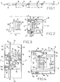
- Figure 1 shows a section of prefabricated electrical pipe according to the invention.
- Figure 2 shows on a larger scale section II - II of the pipeline.
- Figure 3 shows, in top view, the area of a bypass opening, in the clamping position of a support stud.
- FIG. 4 shows on a larger scale a view of the envelope in a section similar to that of FIG. 2.
- Figure 5 is a sectional view of the pipe with a variant of the support stud.
- FIG. 6 shows on a larger scale a detail of the device for elastic expansion and tightening of the stud of FIG. 5.
- Figure 7 is a top view of the pad.
- the prefabricated electrical pipe 10 shown in Figures 1 and 2 comprises a number of sections of the same length assembled end to end. Only a section is shown here for the sake of simplification.
- Each pipe section comprises a metal casing 11 of rectangular section, preferably square to ensure optimum rigidity, with four walls 12, 13, 14, 15, housing several bars or electrically conductive cables 16, here in the form of a sheet 17 of four conductors.
- In the wall 12 are formed at regular intervals of pitch L openings of generally rectangular shape 18, these openings having the purpose of receiving branch connectors 19 for supplying loads not shown from the conductors 16.
- the connectors 19 have an insulating body 20, a starting cable 21 and connection pins, for example in the form of elastic clamps 22 which are able to engage on stripped parts 16a of the conductors 16 to ensure the electrical connection between them and the starting cable.
- the conductors 16 are presently sheathed flexible cables, but they can also be formed by bare or sheathed metal blades or bars.
- the pipe 10 further comprises at one end a supply end 23 and at another end a closure end 24.
- Caps 25 can seal the openings 18 when they are not occupied by connectors.
- Splicing members not shown ensure the mechanical and electrical connection of the pipe sections between them, while fixing members ensure the mechanical connection of the pipe with a horizontal or vertical support wall or ensure the suspension of accessories to the pipeline.
- the envelope 11 of the pipe is produced by folding a sheet blank so as to obtain a closed contour; the folding is carried out for this purpose with longitudinal stapling at 26 of the free edges 27, 28 of the blank, that is to say folding in U with nesting of these edges.
- the watertight stapling strip 26 is provided on a wall 14 of the envelope perpendicular to the wall 12 where the bypass openings 18 are formed and it therefore increases the rigidity of the envelope.
- the axis of the pipe is denoted X-X '
- the plane of the external face of the wall 12 is denoted PP'
- the central axis of the opening 18, perpendicular to P-P ' is denoted Y-Y '.
- the rectangular section devoid of external roughness of the envelope makes it possible to obtain a clean appearance at the same time as observing good rigidity with a fairly small wall thickness.
- the ply 17 of cables 16 is carried by support pads 30 arranged at regular intervals, identical to the intervals L between the openings 18, so that the cables and their support pads form a conductive sub-assembly 31 capable of being introduced by sliding along the axis XX 'of the pipe in its tubular casing 11 with a closed contour.
- Each support stud is associated with an opening 18 and is provided with an expansion device 30a, the implementation of which, through the opening 18, allows the support to be taken and the stud held against the internal faces of the walls of the envelope.
- the stud 30 comprises an insulating body 32 provided, on the side of the opening, with a collar 33 with a chamfered centering edge 33a.
- the body 32 comprises on the side opposite the opening 18 of the legs 34 which can be applied against the internal face 15a of the wall 15 in the phase of introduction of the sub-assembly 31 inside the tubular casing and disengage from this internal face in the clamping phase of the stud.
- the body 32 are provided on the one hand for the connector a housing 35 whose bottom is subdivided into cells 35a and on the other hand, for the conductors 16, a housing 36 with respective slots 36a.
- the side walls 35b of the housing 35 serve to guide complementary shapes 37 of the connector, while the elastic plugs 22 of the latter engage on ribs 38.
- the ribs 38 brace the body 32 between the housings 35, 36 which are 'open in opposite directions; they are thinner than the parts stripped 16a of the conductors 16 which are applied against them in the direction of the opening 18.
- the body 32 of the support stud also has bearings 39 with an axis perpendicular to XX 'and Y-Y', the bearings being bordered by lugs 39a and having to receive the pins or the axis of a pivoting member 40 which constitutes in this example the expansion device 30a.
- the pivoting member 40 comprises a deformable part 42 with an elastic cam configuration located between the legs 34 and applicable against the internal face 15a of the wall 15 and, opposite this cam, rigid support legs 43; when the member 40 pivots, the branches are applicable together in the manner of a comb on the stripped rectilinear parts 16a of the conductors 16.
- the deformable part 42 pivots between an erased position (in dashes in FIG. 3) and a position d 'expansion producing the clamping of the stud (in solid lines) under the effect of the introduction of a tool through the opening 18 and its support on a hollow shape 44 to move the stud along YY' towards the opening 18, with centering of the chamfered edge 33a of the collar 33 in the opening.
- the outer edge 33a of the stud is applied against the edge of the opening while being located substantially at the plane P-P 'of the outer face 12a of the wall 12; this facilitates the fitting of the connector 19 by sliding on the wall 12 until it fits into the housing 35 of the stud.
- the support stud may have a guide finger 34a on the internal face of the wall 14 between the connection of the latter to the wall 12 and the stapling strip 26.
- the support pad On the side of the wall 13, the support pad has an elastic contact blade 50 in the form of a loop embedded at 51 on the pad; this blade has a branch 52 intended to ensure the earthing of the envelope by making contact with an area of the branch with an internal face 13a of the wall 13; the free end 53 of the branch 51 is clamped in the position for inserting the support by a heel 54 secured to the pivoting member and it is released by the heel in the clamping position (in dashes in FIG. 4).
- the electrical pipe comprises support pads which differ from those described above. Similar elements are designated by the same references.
- Each pad 30 comprises a first part 61 providing the housing 35 with its guide surfaces 35b, the collar 33 with centering edge 33a here chamfered and the guide finger 34a, as well as the slots 36a and the ribs 38 for holding the conductors.
- the stud further comprises a second part 62 which provides ribs 63 for applying the bare areas 16a of the conductors 16 to the bottom of the slots 36a; part 62 fits, snaps or is fixed in a similar way to the first part 61.
- the second part 62 of the stud has lateral openings 64 oriented obliquely to YY 'and bordered by an elastic wall 65 notched or toothed each cooperating with a tongue 66 with rack notched or toothed in a complementary manner.
- the teeth 66a of the rack tongue engage in the teeth 65a of the elastic wall, the latter is forced to come into the position indicated in dashes in FIG. 6.
- the teeth have on the one hand an oblique flank, on the other hand a flank substantially parallel to P-P '.
- the tongues 66 are rigid, but they can also be endowed with elasticity or provided with elastic means contributing to reinforce the efficiency of the elastic expansion device 30a. It is understood that the combination of the rack tongues and the elastic walls makes it possible to obtain an elastic force for tightening the stud in the pipeline.
- the stud has an elastic blade 71 for earthing the envelope.
- This blade is similar to the blade 50 and can pass from a sliding position (in dashes in FIG. 6) to an active position in which a branch 72 is applied against the face 13 of the wall 13 of the envelope (in solid lines in FIG. 5) by clearing an area 73 of the blade by means of a tool opposite a retaining shoulder 74 specific to the stud.
- a connection additive 81 can be inserted 81 to weak signal conductors 82 included in the pipeline parallel to the power conductors 16.
- weak signal conductors can be made of twisted or twisted shielded wires to avoid electromagnetic disturbances.
- the additive has plugs or knives 83 with insulation clearance for connection with the conductors 82, these plugs being integral with or electrically connected to contact blades 84 connectable to corresponding conductive parts of the connector.
- the electrical pipe described is produced in the following manner.
- the openings 18 are cut at a predetermined pitch L and the blank is folded according to longitudinal generatrices so as to obtain the envelope 11; by carrying out for this purpose a stapling of the flanges 27, 28 according to a longitudinal strip 26 which ensures a tight closure of the profile, then the exterior of the envelope is painted by any usual method.
- the sheet 17 of conductors whose zones 16a have been previously stripped is placed in the slots 36a of the bodies of molded studs 32,61 arranged at pitch L; in the example of FIGS. 3 and 4, the pivoting members are snapped into the lugs 39a of the studs and are put and maintained in the retracted position which will allow free introduction into the envelope.
- the pivoting members hold the sheet 17 applied against the bottoms of the slots 36a or close to these bottoms.
- the part 62 is fitted or snapped against the part 61 while maintaining the zones 16a of the conductors at the bottom of the slots 36a.
- the pads and cables are retained in mutual position along the axis XX 'by abutment of the sheaths 16b of the cables against the shoulders of the pads.
- each pad When each pad has thus been brought into position in front of its own bypass opening, a tool is introduced into each opening 18 to implement the expansion device.
- the member 40 is pivotally brought from its retracted position between the legs 34 to its expanded clamping position.
- the pivoting of the deformable part 42 determines the displacement of the stud in the direction of the opening 18, the centering of its chamfered edge 33a in the opening, then the elastic tightening of the cam against the internal face 15a of the wall 15.
- the comb formed by the branches 43 is applied against the bare parts 16a of the cables to hold them at the bottom of the slots, and the heel 54 releases the grounding blade 50 so that it applies against the envelope.
- the elastic effect of the pivoting member 40 or the tongues 66 makes it possible to absorb the tolerances and to make up for the clearances.
- the pipeline described can accommodate two groups of conductors instead of just one.
- a second ply 17 'situated between the legs 34 of the studs 30 associated with the first ply is illustrated in dashes in FIG. 4; the corresponding bypass openings 18 ′ are then provided in the wall 15 opposite the wall 12 and the corresponding studs (30 ′) are reversed.
- the bypass connectors can then be placed on both sides of the pipe on studs arranged alternately along the latter.
Abstract
Description
La présente invention concerne un procédé de fabrication d'une canalisation électrique comportant une enveloppe métallique munie à intervalles déterminés d'ouvertures de dérivation et un ensemble conducteur qui est logé dans l'enveloppe et qui est constitué par des conducteurs électriques parallèles appliqués auxdits intervalles sur des plots isolants de support. Elle concerne également les canalisations électriques préfabriquées obtenues par ce procédé.The present invention relates to a method of manufacturing an electrical pipe comprising a metal casing provided at determined intervals with bypass openings and a conductive assembly which is housed in the casing and which consists of parallel electrical conductors applied to said intervals on insulating support pads. It also relates to the prefabricated electrical pipes obtained by this process.
L'enveloppe d'une telle canalisation est habituellement constituée par une goulotte profilée ou en tôle pliée sur laquelle est posé un couvercle ou par deux demi-coquilles en tôle pliée assemblées selon des plans de joints longitudinaux. Pour rendre la canalisation étanche, il faut alors, après introduction de l'ensemble conducteur dans la goulotte, prendre des dispositions de serrage étanche du couvercle sur la goulotte ou d'une demi-coquille sur l'autre, ce qui peut impliquer certains inconvénients.The envelope of such a pipe is usually constituted by a profiled or folded sheet trough on which a cover is placed or by two folded sheet half-shells assembled according to longitudinal joint planes. To make the pipe waterproof, it is then necessary, after introduction of the conductor assembly into the chute, make provisions for tight tightening of the cover on the chute or of a half-shell on the other, which can involve certain drawbacks. .
D'autre part, il est souhaitable de réduire le prix de revient de la canalisation d'une part en diminuant l'épaisseur de paroi de la goulotte tout en restant dans les limites de rigidité prescrites, d'autre part en simplifiant son mode de fabrication.On the other hand, it is desirable to reduce the cost price of the pipe on the one hand by reducing the wall thickness of the chute while remaining within the prescribed stiffness limits, on the other hand by simplifying its method of manufacturing.
L'invention a pour but de réduire le prix de revient d'une canalisation électrique à enveloppe pliée, tout en simplifiant son obtention et en préservant les qualités électrique et mécanique des connexions de dérivation.The invention aims to reduce the cost of an electrical pipe with a folded envelope, while simplifying its production and preserving the electrical and mechanical qualities of the branch connections.
Selon l'invention, le procédé est caractérisé par les étapes suivantes :
- découpe d'ouvertures de dérivation auxdits intervalles dans un flan de tôle métallique,
- pliage du flan avec agrafage de ses bords longitudinaux pour obtenir un profil de tube à bords rejoints de façon étanche,
- introduction de l'ensemble conducteur dans le tube par glissement le long du tube jusqu'au positionnement des plots en regard des ouvertures respectives de dérivation,
- centrage des plots et leur maintien en position centrée par rapport aux ouvertures respectives de dérivation.
- cutting of branch openings at said intervals in a sheet metal blank,
- folding of the blank with stapling of its longitudinal edges to obtain a tube profile with sealed edges,
- introduction of the conductor assembly into the tube by sliding along the tube until the studs are positioned opposite the respective bypass openings,
- centering of the pads and their maintenance in a centered position relative to the respective bypass openings.
De préférence, les plots de support et de dérivation sont pressés contre une paroi interne de l'enveloppe tubulaire, par introduction d'un outil à travers l'ouverture de dérivation pour engendrer une expansion et/ou un arc-boutement du plot contre les faces internes de parois mutuellement opposées de l'enveloppe.Preferably, the support and bypass studs are pressed against an internal wall of the tubular casing, by introduction of a tool through the bypass opening to generate an expansion and / or a bracing of the stud against the internal faces of mutually opposite walls of the envelope.
L'invention concerne également la canalisation ainsi obtenue, à chaque plot de laquelle est de préférence associé un dispositif d'expansion à organe de serrage élastique.The invention also relates to the pipe thus obtained, to each stud of which is preferably associated an expansion device with elastic clamping member.
La description qui va suivre d'un exemple de réalisation en regard des dessins annexés illustre les avantages et caractéristiques de l'invention.The following description of an embodiment with reference to the accompanying drawings illustrates the advantages and characteristics of the invention.
La figure 1 représente un tronçon de canalisation électrique préfabriquée conforme à l'invention.Figure 1 shows a section of prefabricated electrical pipe according to the invention.
La figure 2 montre à plus grande échelle la coupe II - II de la canalisation.Figure 2 shows on a larger scale section II - II of the pipeline.
La figure 3 montre, en vue de dessus, la zone d'une ouverture de dérivation, dans la position de serrage d'un plot de support.Figure 3 shows, in top view, the area of a bypass opening, in the clamping position of a support stud.
La figure 4 représente à plus grande échelle une vue de l'enveloppe selon une coupe analogue à celle de la figure 2.FIG. 4 shows on a larger scale a view of the envelope in a section similar to that of FIG. 2.
La figure 5 est une vue en coupe de la canalisation avec une variante du plot de support.Figure 5 is a sectional view of the pipe with a variant of the support stud.
La figure 6 montre à plus grande échelle un détail du dispositif d'expansion et de serrage élastique du plot de la figure 5.FIG. 6 shows on a larger scale a detail of the device for elastic expansion and tightening of the stud of FIG. 5.
La figure 7 est une vue de dessus du plot.Figure 7 is a top view of the pad.
La canalisation électrique préfabriquée 10 représentée sur les figures 1 et 2 comprend un certain nombre de tronçons de même longueur assemblés bout à bout. Seul un tronçon est ici représenté dans le souci de simplifier. Chaque tronçon de canalisation comprend une enveloppe métallique 11 de section rectangulaire, de préférence carrée pour assurer une rigidité optimale, à quatre parois 12, 13, 14, 15, logeant plusieurs barres ou câbles conducteurs électriques 16, ici sous forme de nappe 17 de quatre conducteurs. Dans la paroi 12 sont ménagées à intervalles réguliers de pas L des ouvertures de forme générale rectangulaire 18, ces ouvertures ayant pour but de recevoir des connecteurs de dérivation 19 pour assurer l'alimentation de charges non représentées à partir des conducteurs 16. Les connecteurs 19 présentent un corps isolant 20, un câble de départ 21 et des broches de connexion, par exemple sous forme de pinces élastiques 22 qui sont aptes à s'engager sur des parties dénudées 16a des conducteurs 16 pour assurer la liaison électrique entre ceux-ci et le câble de départ. Les conducteurs 16 sont présentement des câbles souples gainés, mais ils peuvent aussi bien être constitués par des lames ou barres métalliques nues ou gainées.The prefabricated
La canalisation 10 comporte de plus à une extrémité un embout d'alimentation 23 et à une autre extrémité un embout de fermeture 24. Des capuchons 25 peuvent obturer de manière étanche les ouvertures 18 quand celles-ci ne sont pas occupées par des connecteurs. Des organes d'éclissage non représentés assurent la liaison mécanique et électrique des tronçons de canalisation entre eux, tandis que des organes de fixation assurent la liaison mécanique de la canalisation avec une paroi horizontale ou verticale de support ou assurent la suspension d'accessoires à la canalisation.The
L'enveloppe 11 de la canalisation est réalisée par pliage d'un flan de tôle de manière à obtenir un contour fermé ; le pliage s'effectue à cet effet avec agrafage longitudinal en 26 des bords libres 27, 28 du flan, c'est à dire pliage en U avec imbrication de ces bords. Le bandeau d'agrafage étanche 26 est prévu sur une paroi 14 de l'enveloppe perpendiculaire à la paroi 12 où sont ménagées les ouvertures de dérivation 18 et il augmente de fait la rigidité de l'enveloppe. L'axe de la canalisation est noté X-X', le plan de la face externe de la paroi 12 est noté P-P' et l'axe central de l'ouverture 18, perpendiculaire à P-P', est noté Y-Y'. La section rectangulaire dépourvue d'aspérité extérieure de l'enveloppe permet d'obtenir un aspect net en même temps que d'observer une bonne rigidité avec une épaisseur de paroi assez faible.The
La nappe 17 de câbles 16 est portée par des plots de support 30 disposés à intervalles réguliers, identiques aux intervalles L entre les ouvertures 18, de manière que les câbles et leurs plots de support forment un sous-ensemble conducteur 31 susceptible d'être introduit par glissement selon l'axe X-X' de la canalisation dans son enveloppe tubulaire 11 à contour fermé. Chaque plot de support est associé à une ouverture 18 et est muni d'un dispositif d'expansion 30a dont la mise en oeuvre, par l'ouverture 18, permet la prise d'appui et le maintien du plot contre les faces internes des parois de l'enveloppe. Le plot 30 comporte un corps isolant 32 muni, du côté de l'ouverture, d'un collet 33 à bord de centrage chanfreiné 33a.The
Dans le mode de réalisation des figures 3 et 4, le corps 32 comporte du côté opposé à l'ouverture 18 des jambes 34 qui peuvent s'appliquer contre la face interne 15a de la paroi 15 dans la phase d'introduction du sous-ensemble 31 à l'intérieur de l'enveloppe tubulaire et se dégager de cette face interne dans la phase de serrage du plot. Dans le corps 32 sont prévus d'une part pour le connecteur un logement 35 dont le fond est subdivisé en alvéoles 35a et d'autre part, pour les conducteurs 16, un logement 36 à fentes respectives 36a. Les parois latérales 35b du logement 35 servent à guider des formes complémentaires 37 du connecteur, tandis que les fiches élastiques 22 de celui-ci s'engagent sur des nervures 38. Les nervures 38 entretoisent le corps 32 entre les logements 35,36 qui s'ouvrent en sens opposés ; elles sont plus minces que les parties dénudées 16a des conducteurs 16 qui s'appliquent contre elles dans la direction de l'ouverture 18.In the embodiment of Figures 3 and 4, the
Le corps 32 du plot de support possède aussi des paliers 39 d'axe perpendiculaire à X-X' et Y-Y', les paliers étant bordés par des pattes 39a et devant recevoir les tourillons ou l'axe d'un organe pivotant 40 qui constitue dans cet exemple le dispositif d'expansion 30a.The
L'organe pivotant 40 comprend une partie déformable 42 à configuration de came élastique située entre les jambes 34 et applicable contre la face interne 15a de la paroi 15 et, à l'opposé de cette came, des branches rigides d'appui 43 ; quand l'organe 40 pivote, les branches sont applicables ensemble à la manière d'un peigne sur les parties rectilignes dénudées 16a des conducteurs 16. La partie déformable 42 pivote entre une position effacée (en tirets sur la figure 3) et une position d'expansion produisant le serrage du plot (en traits pleins) sous l'effet de l'introduction d'un outil par l'ouverture 18 et de sa prise d'appui sur une forme en creux 44 pour déplacer le plot selon Y-Y' vers l'ouverture 18, avec centrage du bord chanfreiné 33a du collet 33 dans l'ouverture. On constate que, dans la position de serrage, le bord extérieur 33a du plot est appliqué contre le bord de l'ouverture tout en étant situé sensiblement au niveau du plan P-P' de la face externe 12a de la paroi 12 ; ceci facilite la pose du connecteur 19 par glissement sur la paroi 12 jusqu'à ce qu'il s'emboîte dans le logement 35 du plot. Comme on le voit sur la figure 4, le plot de support peut présenter un doigt 34a de guidage sur la face interne de la paroi 14 entre le raccordement de celle-ci à la paroi 12 et le bandeau d'agrafage 26. Du côté de la paroi 13, le plot de support présente une lame de contact élastique 50 en forme de boucle encastrée en 51 sur le plot ; cette lame présente une branche 52 destinée à assurer la mise à la terre de l'enveloppe par prise de contact d'une zone de la branche avec une face interne 13a de la paroi 13 ; l'extrémité libre 53 de la branche 51 est bridée en position d'introduction du support par un talon 54 solidaire de l'organe pivotant et elle est libérée par le talon en position de serrage (en tirets sur la figure 4).The
Dans le mode de réalisation des figures 5 à 7, la canalisation électrique comprend des plots de support qui diffèrent de ceux décrits précédemment. Les éléments similaires sont désignés par les mêmes références.In the embodiment of Figures 5 to 7, the electrical pipe comprises support pads which differ from those described above. Similar elements are designated by the same references.
Chaque plot 30 comprend une première partie 61 ménageant le logement 35 avec ses surfaces de guidage 35b, le collet 33 à bord de centrage 33a ici chanfreiné et le doigt 34a de guidage, ainsi que les fentes 36a et les nervures 38 de maintien des conducteurs.Each
Le plot comprend en outre une deuxième partie 62 qui ménage des nervures 63 pour appliquer les zones nues 16a des conducteurs 16 au fond des fentes 36a ; la partie 62 semboîte, s'encliquette ou se fixe de manière analogue à la première partie 61. La deuxième partie 62 du plot présente des ouvertures latérales 64 orientées en biais par rapport à Y-Y' et bordées par une paroi élastique 65 crantée ou dentée coopérant chacune avec une languette 66 à crémaillère crantée ou dentée de manière complémentaire. Une poussée exercée selon la direction B sur l'extrémité supérieure 67 de chaque languette, par un outil introduit à travers l'ouverture 18 de l'enveloppe et à travers une ouverture 68 de la partie 61 du plot, fait descendre l'extrémité inférieure 69 de la languette jusqu'à sa butée contre la face interne 15a de la paroi 15 de l'enveloppe ; en même temps, on exerce avec un autre outil selon la direction B' une traction sur la partie 61 ou 62 du plot, pour maintenir ou amener le bord de centrage 33a dans l'ouverture 18. Lorsque les dents 66a de la languette à crémaillère s'engagent dans les dents 65a de la paroi élastique, celle-ci est contrainte à venir dans la position indiquée en tirets sur la figure 6. Les dents présentent d'une part un flanc oblique, d'autre part un flanc sensiblement parallèle à P-P'. Les languettes 66 sont rigides, mais elles peuvent aussi être douées d'élasticité ou dotées de moyens élastiques concourant à renforcer l'efficacité du dispositif d'expansion élastique 30a. On comprend que la combinaison des languettes à crémaillère et des parois élastiques permet d'obtenir un effort élastique de serrage du plot dans la canalisation.The stud further comprises a
Le plot présente une lame élastique 71 de mise à la terre de l'enveloppe. Cette lame est similaire à la lame 50 et peut passer d'une position de glissement (en tirets sur la figure 6) à une position active dans laquelle une branche 72 est appliquée contre la face 13 de la paroi 13 de l'enveloppe (en traits pleins sur la figure 5) par dégagement d'une zone 73 de la lame au moyen d'un outil vis à vis d'un épaulement de retenue 74 propre au plot.The stud has an
Dans une partie latérale du plot est prévu un logement 80 (figure 7) dans lequel peut se glisser un additif de connexion 81 à des conducteurs de signaux faibles 82 inclus dans la canalisation parallèlement aux conducteurs de puissance 16. Ces conducteurs de signaux faibles peuvent être réalisés en fils torsadés ou torsadés blindés pour s'affranchir de perturbations électromagnétiques. L'additif présente des fiches ou couteaux 83 à dégagement d'isolant pour assurer la connexion avec les conducteurs 82, ces fiches étant solidaires de ou électriquement reliées à des lames de contact 84 connectables à des pièces conductrices correspondantes du connecteur.In a lateral part of the stud is provided a housing 80 (FIG. 7) in which a
La canalisation électrique décrite se fabrique de la manière suivante.The electrical pipe described is produced in the following manner.
Dans un flan métallique, on découpe les ouvertures 18 au pas prédéterminé L et l'on plie le flan selon des génératrices longitudinales de manière à obtenir l'enveloppe 11 ; en réalisant pour cela un agrafage des rebords 27, 28 selon un bandeau longitudinal 26 qui assure une fermeture étanche du profil, puis on peint par tout procédé usuel l'extérieur de l'enveloppe. La nappe 17 de conducteurs dont les zones 16a ont été préalablement dénudées est posée dans les fentes 36a des corps de plots moulés 32,61 disposés au pas L ; dans l'exemple des figures 3 et 4, les organes pivotants sont encliquetés dans les pattes 39a des plots et sont mis et maintenus dans la position effacée qui permettra la libre introduction dans l'enveloppe. Les organes pivotants maintiennent la nappe 17 appliquée contre les fonds des fentes 36a ou proche de ces fonds. Dans l'exemple des figures 5 à 7, la partie 62 est emboîtée ou encliquetée contre la partie 61 en maintenant les zones 16a des conducteurs au fond des fentes 36a. Les plots et câbles sont retenus en position mutuelle selon l'axe X-X' par butée des gaines 16b des câbles contre des épaulements des plots.In a metal blank, the
Ensuite on introduit le sous-ensemble formé par la nappe 17 de conducteurs et les plots de support 30 à l'intérieur de l'enveloppe tubulaire 11 par traction ou poussée - de préférence traction -exercée sur un élément terminal non représenté du sous-ensemble.Then we introduce the sub-assembly formed by the
Lorsque chaque plot a été ainsi mis en position devant sa propre ouverture de dérivation, on introduit un outil dans chaque ouverture 18 pour mettre en oeuvre le dispositif d'expansion. Dans l'exemple des figures 3 et 4, on amène par pivotement l'organe 40 de sa position effacée entre les jambes 34 à sa position dilatée de serrage. Le pivotement de la partie déformable 42 détermine le déplacement du plot en direction de l'ouverture 18, le centrage de son bord chanfreiné 33a dans l'ouverture, puis le serrage élastique de la came contre la face interne 15a de la paroi 15. En même temps, le peigne formé par les branches 43 s'applique contre les parties nues 16a des câbles pour les maintenir en fond de fentes, et le talon 54 libère la lame 50 de mise à la terre de sorte que celle-ci s'applique contre l'enveloppe.When each pad has thus been brought into position in front of its own bypass opening, a tool is introduced into each opening 18 to implement the expansion device. In the example of FIGS. 3 and 4, the
Dans l'exemple des figures 5 à 7, un outil s'applique sur l'extrémité supérieure 67 de chaque languette (flèche B - figure 6), tandis que l'on tire le plot selon la flèche B' et qu'on libère le conducteur 71.In the example in FIGS. 5 to 7, a tool is applied to the
L'effet élastique de l'organe pivotant 40 ou des languettes 66 permet d'absorber les tolérances et de rattraper les jeux.The elastic effect of the pivoting
La canalisation décrite peut loger deux groupes de conducteurs au lieu d'un seul. Une deuxième nappe 17' située entre les jambes 34 des plots 30 associés à la première nappe est illustrée en tirets sur la figure 4 ; les ouvertures de dérivation correspondantes 18' sont alors prévues dans la paroi 15 opposée à la paroi 12 et les plots correspondants (30') sont inversés. Les connecteurs de dérivation peuvent alors se poser des deux côtés de la canalisation sur des plots disposés de manière alternée le long de celle-ci.The pipeline described can accommodate two groups of conductors instead of just one. A second ply 17 'situated between the
Il va de soi qu'une pièce de centrage du plot relativement à l'ouverture de dérivation respective peut être rapportée de l'extérieur, avec cependant l'inconvénient de ne plus disposer d'une surface 12 plane ou à faible aspérité au niveau des dérivations. D'autres dispositifs d'expansion à maintien élastique peuvent être prévus en lieu et place de ceux qui ont été décrits.It goes without saying that a centering piece of the stud relative to the respective bypass opening can be added from the outside, with the drawback, however, of no longer having a flat or
Claims (11)
le procédé étant caractérisé par les étapes suivantes :
the process being characterized by the following stages:
Applications Claiming Priority (2)
| Application Number | Priority Date | Filing Date | Title |
|---|---|---|---|
| FR9403251 | 1994-03-17 | ||
| FR9403251A FR2717634B1 (en) | 1994-03-17 | 1994-03-17 | Method of manufacturing an electrical pipe and pipe thus obtained. |
Publications (2)
| Publication Number | Publication Date |
|---|---|
| EP0673089A1 true EP0673089A1 (en) | 1995-09-20 |
| EP0673089B1 EP0673089B1 (en) | 1997-09-03 |
Family
ID=9461232
Family Applications (1)
| Application Number | Title | Priority Date | Filing Date |
|---|---|---|---|
| EP95400504A Expired - Lifetime EP0673089B1 (en) | 1994-03-17 | 1995-03-09 | Cable duct and its manufacturing process |
Country Status (8)
| Country | Link |
|---|---|
| US (1) | US5676557A (en) |
| EP (1) | EP0673089B1 (en) |
| KR (1) | KR100268597B1 (en) |
| CN (1) | CN1055797C (en) |
| BR (1) | BR9501103A (en) |
| DE (1) | DE69500631T2 (en) |
| ES (1) | ES2108541T3 (en) |
| FR (1) | FR2717634B1 (en) |
Cited By (2)
| Publication number | Priority date | Publication date | Assignee | Title |
|---|---|---|---|---|
| EP0798818A1 (en) * | 1996-03-25 | 1997-10-01 | Knürr Mechanik für die Elektronik AG | Housing for multiple sockets |
| US5967818A (en) * | 1996-12-17 | 1999-10-19 | Schneider Electric Sa | Electrical distribution duct with transmission bus |
Families Citing this family (3)
| Publication number | Priority date | Publication date | Assignee | Title |
|---|---|---|---|---|
| DE102004048414B4 (en) * | 2004-10-01 | 2006-09-07 | Fröhlich Biegetechnik GmbH & Co. KG | Element set for creating protective pipelines |
| PE20130052A1 (en) | 2009-11-03 | 2013-02-04 | Orica Explosives Tech Pty Ltd | CONNECTOR |
| EP3288131B1 (en) * | 2016-08-24 | 2020-08-05 | Anord Mardix Databar Busway Limited | Busbar trunking system |
Citations (2)
| Publication number | Priority date | Publication date | Assignee | Title |
|---|---|---|---|---|
| US1809223A (en) * | 1928-05-15 | 1931-06-09 | Armen H Tashjian | Combined conduit and molding |
| GB1148184A (en) * | 1966-07-08 | 1969-04-10 | Henning Jorgensen | Improvements in or relating to ducts for enclosing electrical wiring in buildings |
Family Cites Families (3)
| Publication number | Priority date | Publication date | Assignee | Title |
|---|---|---|---|---|
| SG50306G (en) * | 1981-03-12 | 1986-05-02 | Electrak Int Ltd | Electrical distribution system |
| US4508400A (en) * | 1982-10-18 | 1985-04-02 | Rotaflex P.L.C. | Electrical supply connector for continuous outlet track |
| EP0573047A1 (en) * | 1992-06-05 | 1993-12-08 | Rhc/Spacemaster Corporation | Modular power distribution system |
-
1994
- 1994-03-17 FR FR9403251A patent/FR2717634B1/en not_active Expired - Fee Related
-
1995
- 1995-03-09 DE DE69500631T patent/DE69500631T2/en not_active Expired - Lifetime
- 1995-03-09 ES ES95400504T patent/ES2108541T3/en not_active Expired - Lifetime
- 1995-03-09 EP EP95400504A patent/EP0673089B1/en not_active Expired - Lifetime
- 1995-03-16 BR BR9501103A patent/BR9501103A/en not_active IP Right Cessation
- 1995-03-16 CN CN95102874A patent/CN1055797C/en not_active Expired - Fee Related
- 1995-03-16 US US08/404,957 patent/US5676557A/en not_active Expired - Lifetime
- 1995-03-17 KR KR1019950005653A patent/KR100268597B1/en not_active IP Right Cessation
Patent Citations (2)
| Publication number | Priority date | Publication date | Assignee | Title |
|---|---|---|---|---|
| US1809223A (en) * | 1928-05-15 | 1931-06-09 | Armen H Tashjian | Combined conduit and molding |
| GB1148184A (en) * | 1966-07-08 | 1969-04-10 | Henning Jorgensen | Improvements in or relating to ducts for enclosing electrical wiring in buildings |
Cited By (3)
| Publication number | Priority date | Publication date | Assignee | Title |
|---|---|---|---|---|
| EP0798818A1 (en) * | 1996-03-25 | 1997-10-01 | Knürr Mechanik für die Elektronik AG | Housing for multiple sockets |
| US5967818A (en) * | 1996-12-17 | 1999-10-19 | Schneider Electric Sa | Electrical distribution duct with transmission bus |
| CN1065366C (en) * | 1996-12-17 | 2001-05-02 | 施耐德电器工业公司 | Distribution slot with transmission bus |
Also Published As
| Publication number | Publication date |
|---|---|
| FR2717634B1 (en) | 1996-04-26 |
| DE69500631D1 (en) | 1997-10-09 |
| US5676557A (en) | 1997-10-14 |
| CN1116368A (en) | 1996-02-07 |
| DE69500631T2 (en) | 1998-01-08 |
| BR9501103A (en) | 1995-11-14 |
| KR100268597B1 (en) | 2000-10-16 |
| ES2108541T3 (en) | 1997-12-16 |
| CN1055797C (en) | 2000-08-23 |
| KR950034936A (en) | 1995-12-28 |
| EP0673089B1 (en) | 1997-09-03 |
| FR2717634A1 (en) | 1995-09-22 |
Similar Documents
| Publication | Publication Date | Title |
|---|---|---|
| EP2528166B1 (en) | Earthing clip and earthing assembly | |
| EP0247360B1 (en) | Slotted connection arrangement for an electrical wire and relative connection-tool tip | |
| FR2630865A1 (en) | DERIVATION TERMINAL FOR THE CONNECTION OF A CONDUCTOR OF AN ISOLATED OVERHEAD LINE TO AN INSULATED BYPASS CONDUCTOR | |
| FR2868884A1 (en) | CABLE CONNECTOR COMPRISING A PLURALITY OF TORSADED CONDUCTORS | |
| EP0202972B1 (en) | Sleeve for protecting an electrical junction between an underground cable and an overhead cable insulated at a low voltage | |
| EP0208233B1 (en) | Built-in self-stripping connector assembly for electrical equipment and its connecting tool | |
| EP0913016A1 (en) | Cable insertion device | |
| FR2693040A1 (en) | Connector for electric cables. | |
| EP0673089B1 (en) | Cable duct and its manufacturing process | |
| EP0209452B1 (en) | Multiple-purpose connector for connecting different cable types of electrical conductors together | |
| EP3089295B1 (en) | Electrical interconnection device for an equipotential connection between a cable tray piece and an electrical cable piece. | |
| FR2794901A1 (en) | COMPACT BYPASS CONNECTOR OF AT LEAST ONE BYPASS CABLE ON A MAIN CABLE | |
| FR2792118A1 (en) | METHOD AND DEVICE FOR INTERCONNECTING TERMINALS | |
| FR2541049A1 (en) | SELF-CONTAINING CONNECTION DEVICE | |
| FR3029698A1 (en) | ELECTRICAL CONNECTION ELEMENT WITH INSULATING SHEATHING OF AN ELECTRIC WIRE | |
| EP2079133B1 (en) | Connection terminal equipped with a socket for receiving a pin of an eletric plug, power outlet comprising such a terminal and method of manufacturing such a terminal | |
| FR2794902A1 (en) | COMPACT BYPASS CONNECTOR OF AT LEAST ONE NEUTRAL BYPASS CABLE ON A MAIN NEUTRAL AND SIMULTANEOUS GROUNDED CABLE | |
| EP0744088A1 (en) | Electric plug of the british type | |
| EP1928058B9 (en) | Automatic electrical connection terminal | |
| EP1065749B1 (en) | Connection accessory for electrical apparatus, in particular for modular electrical apparatus | |
| FR2803442A1 (en) | SELF-STRIPPING CONNECTING PIECE THAT CAN BE CONNECTED TO A NEIGHBORING CONNECTING PIECE | |
| FR2623024A1 (en) | Insulation-displacement connector for an insulated electrical conductor | |
| FR2835974A1 (en) | INSULATION MOVEMENT CONNECTION DEVICE | |
| EP0872924B1 (en) | Process of making a lead connector and lead connector obtained thereby | |
| FR2745960A1 (en) | Single input/multiple output cable connector for electrical distribution network |
Legal Events
| Date | Code | Title | Description |
|---|---|---|---|
| PUAI | Public reference made under article 153(3) epc to a published international application that has entered the european phase |
Free format text: ORIGINAL CODE: 0009012 |
|
| 17P | Request for examination filed |
Effective date: 19950317 |
|
| AK | Designated contracting states |
Kind code of ref document: A1 Designated state(s): CH DE ES GB IT LI SE |
|
| GRAG | Despatch of communication of intention to grant |
Free format text: ORIGINAL CODE: EPIDOS AGRA |
|
| GRAH | Despatch of communication of intention to grant a patent |
Free format text: ORIGINAL CODE: EPIDOS IGRA |
|
| 17Q | First examination report despatched |
Effective date: 19970212 |
|
| GRAH | Despatch of communication of intention to grant a patent |
Free format text: ORIGINAL CODE: EPIDOS IGRA |
|
| GRAA | (expected) grant |
Free format text: ORIGINAL CODE: 0009210 |
|
| AK | Designated contracting states |
Kind code of ref document: B1 Designated state(s): CH DE ES GB IT LI SE |
|
| REG | Reference to a national code |
Ref country code: CH Ref legal event code: EP |
|
| ITF | It: translation for a ep patent filed |
Owner name: JACOBACCI & PERANI S.P.A. |
|
| GBT | Gb: translation of ep patent filed (gb section 77(6)(a)/1977) |
Effective date: 19970905 |
|
| REF | Corresponds to: |
Ref document number: 69500631 Country of ref document: DE Date of ref document: 19971009 |
|
| REG | Reference to a national code |
Ref country code: ES Ref legal event code: FG2A Ref document number: 2108541 Country of ref document: ES Kind code of ref document: T3 |
|
| PLBE | No opposition filed within time limit |
Free format text: ORIGINAL CODE: 0009261 |
|
| STAA | Information on the status of an ep patent application or granted ep patent |
Free format text: STATUS: NO OPPOSITION FILED WITHIN TIME LIMIT |
|
| 26N | No opposition filed | ||
| PG25 | Lapsed in a contracting state [announced via postgrant information from national office to epo] |
Ref country code: LI Free format text: LAPSE BECAUSE OF NON-PAYMENT OF DUE FEES Effective date: 19990331 Ref country code: CH Free format text: LAPSE BECAUSE OF NON-PAYMENT OF DUE FEES Effective date: 19990331 |
|
| REG | Reference to a national code |
Ref country code: CH Ref legal event code: PL |
|
| REG | Reference to a national code |
Ref country code: GB Ref legal event code: IF02 |
|
| PGFP | Annual fee paid to national office [announced via postgrant information from national office to epo] |
Ref country code: SE Payment date: 20110218 Year of fee payment: 17 |
|
| PGFP | Annual fee paid to national office [announced via postgrant information from national office to epo] |
Ref country code: GB Payment date: 20110222 Year of fee payment: 17 Ref country code: DE Payment date: 20110202 Year of fee payment: 17 Ref country code: ES Payment date: 20110321 Year of fee payment: 17 |
|
| PGFP | Annual fee paid to national office [announced via postgrant information from national office to epo] |
Ref country code: IT Payment date: 20110330 Year of fee payment: 17 |
|
| REG | Reference to a national code |
Ref country code: DE Ref legal event code: R084 Ref document number: 69500631 Country of ref document: DE Effective date: 20111228 |
|
| REG | Reference to a national code |
Ref country code: SE Ref legal event code: EUG |
|
| PG25 | Lapsed in a contracting state [announced via postgrant information from national office to epo] |
Ref country code: SE Free format text: LAPSE BECAUSE OF NON-PAYMENT OF DUE FEES Effective date: 20120310 |
|
| GBPC | Gb: european patent ceased through non-payment of renewal fee |
Effective date: 20120309 |
|
| PG25 | Lapsed in a contracting state [announced via postgrant information from national office to epo] |
Ref country code: GB Free format text: LAPSE BECAUSE OF NON-PAYMENT OF DUE FEES Effective date: 20120309 |
|
| REG | Reference to a national code |
Ref country code: DE Ref legal event code: R119 Ref document number: 69500631 Country of ref document: DE Effective date: 20121002 |
|
| PG25 | Lapsed in a contracting state [announced via postgrant information from national office to epo] |
Ref country code: IT Free format text: LAPSE BECAUSE OF NON-PAYMENT OF DUE FEES Effective date: 20120309 |
|
| REG | Reference to a national code |
Ref country code: ES Ref legal event code: FD2A Effective date: 20130710 |
|
| PG25 | Lapsed in a contracting state [announced via postgrant information from national office to epo] |
Ref country code: ES Free format text: LAPSE BECAUSE OF NON-PAYMENT OF DUE FEES Effective date: 20120310 |
|
| PG25 | Lapsed in a contracting state [announced via postgrant information from national office to epo] |
Ref country code: DE Free format text: LAPSE BECAUSE OF NON-PAYMENT OF DUE FEES Effective date: 20121002 |