EP0872924B1 - Process of making a lead connector and lead connector obtained thereby - Google Patents
Process of making a lead connector and lead connector obtained thereby Download PDFInfo
- Publication number
- EP0872924B1 EP0872924B1 EP19980400884 EP98400884A EP0872924B1 EP 0872924 B1 EP0872924 B1 EP 0872924B1 EP 19980400884 EP19980400884 EP 19980400884 EP 98400884 A EP98400884 A EP 98400884A EP 0872924 B1 EP0872924 B1 EP 0872924B1
- Authority
- EP
- European Patent Office
- Prior art keywords
- connector
- lead
- casing
- fastening
- manufacturing
- Prior art date
- Legal status (The legal status is an assumption and is not a legal conclusion. Google has not performed a legal analysis and makes no representation as to the accuracy of the status listed.)
- Expired - Lifetime
Links
Images


Classifications
-
- H—ELECTRICITY
- H01—ELECTRIC ELEMENTS
- H01R—ELECTRICALLY-CONDUCTIVE CONNECTIONS; STRUCTURAL ASSOCIATIONS OF A PLURALITY OF MUTUALLY-INSULATED ELECTRICAL CONNECTING ELEMENTS; COUPLING DEVICES; CURRENT COLLECTORS
- H01R43/00—Apparatus or processes specially adapted for manufacturing, assembling, maintaining, or repairing of line connectors or current collectors or for joining electric conductors
- H01R43/20—Apparatus or processes specially adapted for manufacturing, assembling, maintaining, or repairing of line connectors or current collectors or for joining electric conductors for assembling or disassembling contact members with insulating base, case or sleeve
- H01R43/24—Assembling by moulding on contact members
-
- H—ELECTRICITY
- H01—ELECTRIC ELEMENTS
- H01R—ELECTRICALLY-CONDUCTIVE CONNECTIONS; STRUCTURAL ASSOCIATIONS OF A PLURALITY OF MUTUALLY-INSULATED ELECTRICAL CONNECTING ELEMENTS; COUPLING DEVICES; CURRENT COLLECTORS
- H01R13/00—Details of coupling devices of the kinds covered by groups H01R12/70 or H01R24/00 - H01R33/00
- H01R13/648—Protective earth or shield arrangements on coupling devices, e.g. anti-static shielding
- H01R13/652—Protective earth or shield arrangements on coupling devices, e.g. anti-static shielding with earth pin, blade or socket
-
- H—ELECTRICITY
- H01—ELECTRIC ELEMENTS
- H01R—ELECTRICALLY-CONDUCTIVE CONNECTIONS; STRUCTURAL ASSOCIATIONS OF A PLURALITY OF MUTUALLY-INSULATED ELECTRICAL CONNECTING ELEMENTS; COUPLING DEVICES; CURRENT COLLECTORS
- H01R2103/00—Two poles
-
- H—ELECTRICITY
- H01—ELECTRIC ELEMENTS
- H01R—ELECTRICALLY-CONDUCTIVE CONNECTIONS; STRUCTURAL ASSOCIATIONS OF A PLURALITY OF MUTUALLY-INSULATED ELECTRICAL CONNECTING ELEMENTS; COUPLING DEVICES; CURRENT COLLECTORS
- H01R24/00—Two-part coupling devices, or either of their cooperating parts, characterised by their overall structure
- H01R24/28—Coupling parts carrying pins, blades or analogous contacts and secured only to wire or cable
- H01R24/30—Coupling parts carrying pins, blades or analogous contacts and secured only to wire or cable with additional earth or shield contacts
Definitions
- the present invention relates to a method of manufacturing a cord power supply of a particular type, intended for the connection of a device to a source of electrical energy.
- This cord will be designated below by "cord connector ".
- the connector cord targeted by the manufacturing process comprises a cord proper including electrical conductors traditionally connected to a first end of the cord, to pins carried by an electrical outlet suitable for connection to the power source.
- the electrical conductors are connected to lugs carried by a connector, said lugs being intended to be fitted with lugs connected to electrical conductors fixed inside the device to connected. These latter lugs are accessible through an opening in the outer wall of the device.
- Said connector is intended to close the opening, a times its lugs coupled to those of the device.
- the connector made in one non-conductive material and having a section allowing its introduction into the opening comprises a peripheral guard intended to come into tight contact with said outer wall of the device. The connector thus performs a multiple function, housing for the terminals, closing the opening, for a strictly aesthetic, but also and above all of protection of the electrical connection against stresses on the cord, and finally insulation of electrical components of the device vis-à-vis the outside.
- a power cord provided with such a connector is described in the request.
- the connector cord targeted by the manufacturing process of the invention can be mounted on the device at the last moment, according to the user's request.
- connector cords of the type targeted by the invention that is to say comprising a cord proper including electrical conductors and carrying, at a first end, an electrical outlet adapted to be connected to the source of energy, and, at a second end, a connector carrying lugs intended for be fitted with device lugs accessible through an opening in the outer wall of the latter, said connector to be embedded in said opening up to a peripheral guard intended to come into tight contact with the outer wall of the device around said opening.
- the connector is produced in the form of a housing, one-piece or not, molded regardless of the power cord.
- the assembly of the components of the case forming the connector and fixing the latter on the cord are made by means mechanical, latching or pinching. This requires parts with legs, teeth and other details which imply great precision of dimensions and entail a significant production cost.
- the functions of the connector protecting the connection electric in the face of stresses on the cord, and insulation of electrical components of the device vis-à-vis the outside, are less well insured that in the embodiments where the connector is molded at the same time as the cord, this which is generally the case with removable traditional connector cords.
- a simultaneous molding of the connector and the cord is necessarily done in a plastic that is both flexible and stable, to meet the requirements cables and connector.
- This is not recommended for a cord connector of the type covered by the present invention, insofar as the connector itself must be made of perfectly stable plastic, in other words rigid, since, unlike removable connector cords, it is the connector himself who must ensure the closure of the opening of the external wall of the device electric.
- the connector with peripheral guard is indeed fixed in the opening by latching means or screw connection, which require rigid plastic.
- the invention thus relates to a method of manufacturing a connector cord, which avoids the complicated structures of known connection boxes, and results in an optimal connection between the housing or connector and the cord.
- the front part of the case, including the peripheral guard is made of rigid plastic, suitable for the sealing function of the opening of the device, assigned to the connector.
- the rear part of the case, upstream of the peripheral guard in the direction of the power supply, is covered with flexible plastic up to the cord, which allows a connection without fault between the connector base and the cord.
- the present invention also relates to a connector cord obtained according to this manufacturing process.
- the connector cord thus produced ensures under optimal conditions the protection functions of the electrical connection facing stresses on the cord, and insulation of components the appliance vis-à-vis the outside.
- the invention relates to an electrical appliance provided with a connector cord obtained in accordance with the above manufacturing process.
- This device presents the advantages listed in the introduction, linked to the type of connector cord, for optimal security, without the price of the connector cord being affected.
- connection box is molded from polyamide, a material noble plastic which gives the desired rigidity and also has the advantage of withstand the high temperatures that can be transmitted to the outer wall of the electrical appliance, especially in the case of a metal wall.
- the connector housing is made up of from two inserts to be assembled, the first of which carries the peripheral guard, is suitable for reviewing the connector lugs, while the second serves as a spacer for the electrical conductors of the cord. This construction greatly facilitates the assembly of lugs and bare electrical wires of the cord, before the final operation overmolding.
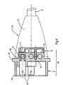
- the electrical device shown schematically by the parallelepiped 1, intended to be connected to a source of electrical energy by a connector cord 2 of the type targeted by the manufacturing process according to the invention has on an outer face 10 an opening 12 provided for receiving a connector.
- the opening 12 reveals conductive wires provided with contacts electrical or lugs 15.
- the connector cord 2 comprises a cord 3 provided at one end with a plug 20 intended to be connected to the source.
- the socket 20 carries pins to which are connected the conductors of the cord 3 not shown.
- the cord 3 On the opposite side, the cord 3 carries a connector 22 comprising electrical contacts or lugs 25 connected to the cord conductors and adapted to be fitted onto the corresponding lugs 15 of device 1.
- the connector 22 also carries a peripheral guard 24 intended to ensure a tight closure of the opening 12, as well as fixing means in the opening 12, in the form of latching tabs 23. These are worn here by two of the faces of the connector 22 intended to come opposite the edges 17 of the opening 12. Alternatively, provision may be made for a screw connection, holes being then provided for this purpose in the peripheral guard 24 and the outer wall 10 surrounding the opening 12.
- the fitting can be done during the manufacture of the device or later, possibly by the user himself.
- the connector 22 is then embedded in the opening 12, the peripheral guard 24 bearing, so sealed against the region 19 of the outer wall which surrounds the opening 12.
- the first insert 5 is a hollow part of generally rectangular section, the bottom wall 7 has three housings 8 adapted to receive the lugs 25, these being produced as standard in the form of nickel-plated brass tabs for be able to be coupled to the internal lugs 15 of the device 1.
- the outer wall 9 of the insert 5 carries a flange 24 forming the peripheral guard and delimiting a part front 9a and a rear part 9b.
- the front part 9a relates to each of its faces upper and lower outer pair of flexible latching legs 23 to inclined ramps, allowing permanent fixing of connector 22 in the opening 12 of the device 1.
- the second insert 6 comprises three adapted housings 11 the passage of the electrical conductors (not shown) of the cord 3, and thus serves spacer to these.
- a terminal 25 is placed in each of the three housings 8 of the first insert 5, after which the second insert 6 is placed on the rear face 13 of the first insert 5, so that their respective housings 8 and 11 are aligned.
- This operation of centering is facilitated by the provision of a housing 14 formed in the rear wall of the insert 5, adapted to receive a projecting part 16 of the insert 6.
- a rigid housing 18 comprising, on either side of the peripheral guard 24, a front part 9a and a rear part 9b, the latter being extended by insert 6.
- earth and neutral conductor wires (not shown) of the cord 3 are introduced into the housings 11 and connected to the terminals 25 corresponding. All these operations take place advantageously on a line automatic mounting.
- the final operation consists of an overmolding of a material flexible plastic such as polyvinyl chloride, from the rear part 9a, 6 of the housing 18, until covering an adjacent part of the cord 3, to form a flexible body, of generally frustoconical, 21.
- a connector cord 2 is thus obtained which, due to the connection by molding of its components including the cord, fills under conditions optimal security the sealing functions of the opening 12 of the device 1, the peripheral guard 24 being applied against the wall 10, and protection of the electrical connection between lugs 15 and 25 with regard to stresses on the cord 3.
- the noble material chosen - from polyamide 6,6 in the example given - for the front part 9a of the connector Due to the qualities of thermal and mechanical stability of the noble material chosen - from polyamide 6,6 in the example given - for the front part 9a of the connector, the latter thus has a role of thermal insulator between the wall 10 of the appliance, which can be very hot if it is an iron or a waffle iron, and the rear part of the connector 21 secured to the end of the cable 3.
- the overmolding of this rear part can be made of a less noble material - polychloride vinyl, in the example given - especially because it is in an area cold, thermally insulated from the wall 10.
- the device 1 intended to receive this connector cord requires no particular adaptation of its receiving wall, due to the fact that the cord is easily introduced - by simple clipping according to the preferred embodiment of the invention - in a opening traditionally provided for the male part of a connector cord conventional removable, of the type described in the introduction.
- the option of the traditional connector cord or the connector cord according to the invention remains open until the last moment.
Landscapes
- Engineering & Computer Science (AREA)
- Manufacturing & Machinery (AREA)
- Connector Housings Or Holding Contact Members (AREA)
- Manufacturing Of Electrical Connectors (AREA)
Description
La présente invention concerne un procédé de fabrication d'un cordon d'alimentation électrique d'un type particulier, destiné au raccordement d'un appareil à une source d'énergie électrique. Ce cordon sera désigné ci-après par "cordon connecteur".The present invention relates to a method of manufacturing a cord power supply of a particular type, intended for the connection of a device to a source of electrical energy. This cord will be designated below by "cord connector ".
Le cordon connecteur visé par le procédé de fabrication comporte un cordon proprement dit incluant des conducteurs électriques reliés, de manière traditionnelle, à une première extrémité du cordon, à des broches portées par une prise électrique adaptée à être branchée à la source d'énergie.The connector cord targeted by the manufacturing process comprises a cord proper including electrical conductors traditionally connected to a first end of the cord, to pins carried by an electrical outlet suitable for connection to the power source.
A une deuxième extrémité du cordon, les conducteurs électriques sont reliés à des cosses portées par un connecteur, lesdites cosses étant destinées à être emboítées avec des cosses reliées à des conducteurs électriques fixées à l'intérieur de l'appareil à raccorder. Ces dernières cosses sont accessibles par une ouverture ménagée dans la paroi extérieure de l'appareil. Ledit connecteur est destiné à obturer l'ouverture, une fois ses cosses couplées à celles de l'appareil. A cet effet, le connecteur, réalisé en une matière non conductrice et ayant une section permettant son introduction dans l'ouverture, comporte une garde périphérique destinée à venir en contact étanche avec ladite paroi extérieure de l'appareil. Le connecteur assure ainsi une fonction multiple, de logement pour les cosses, d'obturation de l'ouverture, dans un but strictement esthétique, mais aussi et surtout de protection de la connexion électrique face aux sollicitations qui pèsent sur le cordon, et enfin d'isolation des composants électriques de l'appareil vis-à-vis de l'extérieur.At a second end of the cord, the electrical conductors are connected to lugs carried by a connector, said lugs being intended to be fitted with lugs connected to electrical conductors fixed inside the device to connected. These latter lugs are accessible through an opening in the outer wall of the device. Said connector is intended to close the opening, a times its lugs coupled to those of the device. For this purpose, the connector, made in one non-conductive material and having a section allowing its introduction into the opening comprises a peripheral guard intended to come into tight contact with said outer wall of the device. The connector thus performs a multiple function, housing for the terminals, closing the opening, for a strictly aesthetic, but also and above all of protection of the electrical connection against stresses on the cord, and finally insulation of electrical components of the device vis-à-vis the outside.
Un cordon d'alimentation muni d'un tel connecteur est décrit dans la demande de brevet français n° 95 10209 de la Déposante. Il allie certains avantages des cordons traditionnellement fixés à demeure sur l'appareil, et dépourvus de connecteur, et des cordons amovibles traditionnels, se présentant sous la forme d'une prise femelle destinée à être encastrée sur des broches mâles en saillie sur la paroi de l'appareil. Ainsi, le cordon connecteur visé par le procédé de fabrication de l'invention peut être monté sur l'appareil au dernier moment, en fonction de la demande de l'utilisateur. En outre, il est possible de se raccorder dans l'appareil à des conducteurs gainés d'un autre matériau que celui du cordon, pour un nombre de composants et un coût de fabrication plus faibles qu'avec un cordon amovible, à connecteur classique.A power cord provided with such a connector is described in the request. French Patent No. 95 10209 to the Applicant. It combines certain advantages of cords traditionally permanently fixed to the device, and without connector, and traditional removable cords, in the form of a female plug intended to be embedded on male pins projecting from the wall of the device. Thus, the connector cord targeted by the manufacturing process of the invention can be mounted on the device at the last moment, according to the user's request. In in addition, it is possible to connect in the device to sheathed conductors of another material than that of the cord, for a number of components and a manufacturing cost lower than with a removable cord, with conventional connector.
On connaít également par les documents EP-A-0 569 659, EP-A-0 129 424 ou FR-A-2 698 492, des cordons connecteurs du type visé par l'invention, c'est-à-dire comprenant un cordon proprement dit incluant des conducteurs électriques et portant, à une première extrémité, une prise électrique adaptée à être branchée à la source d'énergie, et, à une deuxième extrémité un connecteur portant des cosses destinées à être emboítées avec des cosses de l'appareil accessibles par une ouverture ménagée dans la paroi extérieure de ce dernier, ledit connecteur devant être encastré dans ladite ouverture jusqu'à une garde périphérique destinée à venir en contact étanche avec la paroi extérieure de l'appareil autour de ladite ouverture. Dans ces cordons connecteurs connus, le connecteur est réalisé sous forme de boítier, monobloc ou non, moulé indépendamment du cordon électrique. L'assemblage des composants du boitier formant le connecteur et la fixation de ce dernier sur le cordon se font par des moyens mécaniques, d'encliquetage ou de pincement. Ceci nécessite des pièces comportant des pattes, des dents et autres détails qui supposent une grande précision de cotes et entraínent un coût de production non négligeable.We also know from documents EP-A-0 569 659, EP-A-0 129 424 or FR-A-2 698 492, connector cords of the type targeted by the invention, that is to say comprising a cord proper including electrical conductors and carrying, at a first end, an electrical outlet adapted to be connected to the source of energy, and, at a second end, a connector carrying lugs intended for be fitted with device lugs accessible through an opening in the outer wall of the latter, said connector to be embedded in said opening up to a peripheral guard intended to come into tight contact with the outer wall of the device around said opening. In these connector cords known, the connector is produced in the form of a housing, one-piece or not, molded regardless of the power cord. The assembly of the components of the case forming the connector and fixing the latter on the cord are made by means mechanical, latching or pinching. This requires parts with legs, teeth and other details which imply great precision of dimensions and entail a significant production cost.
D'autre part, les fonctions du connecteur, de protection de la connexion électrique face aux sollicitations qui pèsent sur le cordon, et d'isolation des composants électriques de l'appareil vis-à-vis de l'extérieur, sont moins bien assurées que dans les réalisations où le connecteur est moulé en même temps que le cordon, ce qui est généralement le cas des cordons connecteurs traditionnels amovibles.On the other hand, the functions of the connector, protecting the connection electric in the face of stresses on the cord, and insulation of electrical components of the device vis-à-vis the outside, are less well insured that in the embodiments where the connector is molded at the same time as the cord, this which is generally the case with removable traditional connector cords.
Un moulage simultané du connecteur et du cordon se fait nécessairement dans une matière plastique à la fois souple et stable, pour répondre aux exigences mécaniques du cordon et du connecteur. Ceci n'est pas recommandé pour un cordon connecteur du type visé par la présente invention, dans la mesure où le connecteur lui-même doit être réalisé en une matière plastique parfaitement stable, autrement dit rigide, puisque, contrairement aux cordons connecteurs amovibles, c'est le connecteur lui-même qui doit assurer l'obturation de l'ouverture de la paroi extérieure de l'appareil électrique. Le connecteur à garde périphérique est en effet fixé dans l'ouverture par des moyens d'encliquetage ou une liaison par vis, qui exigent une matière plastique rigide.A simultaneous molding of the connector and the cord is necessarily done in a plastic that is both flexible and stable, to meet the requirements cables and connector. This is not recommended for a cord connector of the type covered by the present invention, insofar as the connector itself must be made of perfectly stable plastic, in other words rigid, since, unlike removable connector cords, it is the connector himself who must ensure the closure of the opening of the external wall of the device electric. The connector with peripheral guard is indeed fixed in the opening by latching means or screw connection, which require rigid plastic.
Le document US-A-4 574 474 montre un procédé de surmoulage d'un connecteur relié à un cordon. Le connecteur, une fois réalisé, ne présente pas de garde phériphérique délimitant une partie avant destinée à être encastrée.Document US-A-4,574,474 shows a process for overmolding a connector connected to a cord. The connector, once made, does not have no peripheral guard delimiting a front part intended to be embedded.
L'invention vise ainsi un procédé de fabrication d'un cordon connecteur, qui évite les structures compliquées des boítiers de connection connus, et se traduit par une liaison optimale entre le boítier ou connecteur et le cordon.The invention thus relates to a method of manufacturing a connector cord, which avoids the complicated structures of known connection boxes, and results in an optimal connection between the housing or connector and the cord.
Plus précisément, l'invention concerne un procédé de fabrication et de fixation
d'un connecteur sur le cordon, comprenant les étapes suivantes:
Ce procédé résoud le problème à la base de l'invention par l'emploi judicieux de deux matières plastiques présentant des propriétés différentes, pour les diverses parties du connecteur. La partie avant du boítier, y compris la garde périphérique, est réalisée dans une matière plastique rigide, adaptée à la fonction d'obturation de l'ouverture de l'appareil, dévolue au connecteur. La partie arrière du boítier, en amont de la garde périphérique dans le sens de l'alimentation électrique, est recouverte de matière plastique souple jusqu'au cordon, ce qui permet d'obtenir une liaison sans faille entre la base du connecteur et le cordon.This method solves the problem underlying the invention by judicious use. of two plastics with different properties, for the different connector parts. The front part of the case, including the peripheral guard, is made of rigid plastic, suitable for the sealing function of the opening of the device, assigned to the connector. The rear part of the case, upstream of the peripheral guard in the direction of the power supply, is covered with flexible plastic up to the cord, which allows a connection without fault between the connector base and the cord.
La présente invention vise également un cordon connecteur obtenu conformément à ce procédé de fabrication. Le cordon connecteur ainsi réalisé assure dans des conditions optimales les fonctions de protection de la connexion électrique face aux sollicitations qui pèsent sur le cordon, et d'isolation des composants électriques de l'appareil vis-à-vis de l'extérieur.The present invention also relates to a connector cord obtained according to this manufacturing process. The connector cord thus produced ensures under optimal conditions the protection functions of the electrical connection facing stresses on the cord, and insulation of components the appliance vis-à-vis the outside.
Enfin, l'invention vise un appareil électrique muni d'un cordon connecteur obtenu conformément au procédé de fabrication précité. Cet appareil présente les avantages énumérés en introduction, liés au type de cordon connecteur, pour une sécurité optimale, sans que le prix du cordon connecteur s'en trouve grevé.Finally, the invention relates to an electrical appliance provided with a connector cord obtained in accordance with the above manufacturing process. This device presents the advantages listed in the introduction, linked to the type of connector cord, for optimal security, without the price of the connector cord being affected.
Avantageusement, le boítier de connexion est moulé en polyamide, matière plastique noble qui confère la rigidité souhaitée et présente de plus l'avantage de résister aux températures élevées qui peuvent être transmises à la paroi extérieure de l'appareil électrique, surtout dans le cas d'un paroi en métal.Advantageously, the connection box is molded from polyamide, a material noble plastic which gives the desired rigidity and also has the advantage of withstand the high temperatures that can be transmitted to the outer wall of the electrical appliance, especially in the case of a metal wall.
Dans un mode de réalisation préféré, le boítier du connecteur est constitué à partir de deux inserts à assembler, dont le premier, porteur de la garde périphérique, est adapté à revoir les cosses du connecteur, tandis que le second sert d'espaceur pour les conducteurs électriques du cordon. Cette construction facilite grandement le montage des cosses et des fils électriques dénudés du cordon, avant l'opération finale de surmoulage.In a preferred embodiment, the connector housing is made up of from two inserts to be assembled, the first of which carries the peripheral guard, is suitable for reviewing the connector lugs, while the second serves as a spacer for the electrical conductors of the cord. This construction greatly facilitates the assembly of lugs and bare electrical wires of the cord, before the final operation overmolding.
D'autres particularités et avantages de l'invention apparaítront encore dans la description qui suit.Other features and advantages of the invention will become apparent in the description which follows.
Aux dessins annexés, donnés à titre d'exemples non limitatifs;
- la figure 1 montre schématiquement en perspective un cordon connecteur du type visé par le procédé de fabrication selon l'invention,
- la figure 2 est une vue en bout du connecteur muni des cosses,
- la figure 3 est une coupe axiale du connecteur selon le plan III-III de la figure 2,
- la figure 4 est une coupe selon le plan IV-IV de la figure 2.
- FIG. 1 schematically shows in perspective a connector cord of the type targeted by the manufacturing method according to the invention,
- FIG. 2 is an end view of the connector provided with lugs,
- FIG. 3 is an axial section of the connector according to the plane III-III of FIG. 2,
- FIG. 4 is a section along the plane IV-IV of FIG. 2.
En référence à la figure 1, l'appareil électrique schématisé par le
parallélépipède 1, destiné à être raccordé à une source d'énergie électrique par un
cordon connecteur 2 du type visé par le procédé de fabrication selon l'invention,
présente sur une face extérieure 10 une ouverture 12 prévue pour recevoir un
connecteur. L'ouverture 12 laisse apparaítre des fils conducteurs munis de contacts
électriques ou cosses 15.Referring to Figure 1, the electrical device shown schematically by the
parallelepiped 1, intended to be connected to a source of electrical energy by a
connector cord 2 of the type targeted by the manufacturing process according to the invention,
has on an
Le cordon connecteur 2 comporte un cordon 3 muni à une extrémité d'une prise
20 destinée à être branchée à la source. La prise 20 porte des broches auxquelles sont
reliés les conducteurs du cordon 3 non représentés. Du côté opposé, le cordon 3 porte
un connecteur 22 comportant des contacts électriques ou cosses 25 reliés aux
conducteurs du cordon et adaptés à être emboítés sur les cosses correspondantes 15 de
l'appareil 1.The connector cord 2 comprises a
Le connecteur 22 porte par ailleurs une garde périphérique 24 destinée à
assurer une obturation étanche de l'ouverture 12, ainsi que des moyens de fixation
dans l'ouverture 12, sous la forme de pattes d'encliquetage 23. Celles-ci sont portées
ici par deux des faces du connecteur 22 destinées à venir en regard des chants 17 de
l'ouverture 12. Alternativement, on peut prévoir une liaison par vis, des trous étant
alors prévus à cet effet dans la garde périphérique 24 et la paroi extérieure 10
entourant l'ouverture 12.The
L'emboítement peut être réalisé lors de la fabrication de l'appareil ou
ultérieurement, éventuellement par l'utilisateur lui-même. Le connecteur 22 est ensuite
encastré dans l'ouverture 12, la garde périphérique 24 prenant appui, de manière
étanche, contre la région 19 de la paroi extérieure qui entoure l'ouverture 12.The fitting can be done during the manufacture of the device or
later, possibly by the user himself. The
On va maintenant décrire les étapes du procédé de fabrication conforme à l'invention, du cordon connecteur qui vient d'être décrit dans ses caractéristiques fonctionnelles. Ces étapes seront mieux comprises en référence aux figures 3 et 4 montrant la structure interne d'un cordon connecteur ainsi obtenu, selon des options préférées du procédé de fabrication.We will now describe the steps of the manufacturing process according to the invention, the connector cord which has just been described in its characteristics functional. These steps will be better understood with reference to Figures 3 and 4 showing the internal structure of a connector cord thus obtained, according to options preferred in the manufacturing process.
On réalise tout d'abord par moulage deux inserts 5, 6 en polyamide 6,6. Le
premier insert 5 est une pièce creuse de section généralement rectangulaire, dont la
paroi de fond 7 comporte trois logements 8 adaptés à recevoir les cosses 25, celles-ci
étant réalisées de manière standard sous forme de languettes en laiton nickelé pour
pouvoir être couplées aux cosses 15 internes de l'appareil 1. La paroi extérieure 9 de
l'insert 5 porte un flasque 24 formant la garde périphérique et délimitant une partie
avant 9a et une partie arrière 9b. La partie avant 9a porte sur chacune des ses faces
extérieures supérieure et inférieure une paire de pattes flexibles d'encliquetage 23 à
rampes inclinées, permettant la fixation à demeure du connecteur 22 dans
l'ouverture 12 de l'appareil 1. Le second insert 6 comporte trois logements 11 adaptés
au passage des conducteurs électriques (non représentés) du cordon 3, et sert ainsi
d'espaceur à ces derniers.First of all, two polyamide 6.6
Conformément au procédé de l'invention, après le moulage des deux inserts 5
et 6, on place dans chacun des trois logements 8 du premier insert 5 une cosse 25,
après quoi on place le second insert 6 sur la face arrière 13 du premier insert 5, de
manière que leurs logements respectifs 8 et 11 se trouvent alignés. Cette opération de
centrage est facilitée par la disposition d'un logement 14 ménagé dans la paroi arrière
de l'insert 5, adapté à recevoir une partie en saillie 16 de l'insert 6. On obtient après
assemblage un boítier rigide 18 comportant, de part et d'autre de la garde périphérique
24, une partie avant 9a et une partie arrière 9b, cette dernière étant prolongée par
l'insert 6.According to the process of the invention, after the molding of the two
Après dénudage des fils conducteurs phase, terre et neutre (non représentés) du
cordon 3, ces derniers sont introduits dans les logements 11 et connectés aux cosses 25
correspondantes. Toutes ces opérations prennent place avantageusement sur une ligne
automatique de montage. L'opération finale consiste en un surmoulage en une matière
plastique souple telle qu'un polychlorure de vinyle, de la partie arrière 9a, 6 du boítier
18, jusqu'à recouvrir une partie adjacente du cordon 3, pour former un corps souple, de
forme généralement tronconique, 21.After stripping of the phase, earth and neutral conductor wires (not shown) of the
On obtient ainsi un cordon connecteur 2 qui, du fait de la solidarisation par
moulage de ses composants y compris du cordon, remplit dans des conditions
optimales de sécurité les fonctions d'obturation étanche de l'ouverture 12 de
l'appareil 1, la garde périphérique 24 se trouvant appliquée contre la paroi 10, et de
protection de la connexion électrique entre les cosses 15 et 25 à l'égard des
sollicitations qui pèsent sur le cordon 3.A connector cord 2 is thus obtained which, due to the connection by
molding of its components including the cord, fills under conditions
optimal security the sealing functions of the
Du fait des qualités de stabilité thermique et mécanique de la matière noble
choisie - du polyamide 6,6 dans l'exemple donné - pour la partie avant 9a du
connecteur, cette dernière a ainsi un rôle d'isolant thermique entre la paroi 10 de
l'appareil, qui peut être très chaude s'il s'agit d'un fer à repasser ou d'un gaufrier, et la
partie arrière du connecteur 21 solidaire de l'extrémité du câble 3. Le surmoulage de
cette partie arrière peut être réalisé en une matière moins noble - du polychlorure de
vinyle, dans l'exemple donné - en particulier du fait qu'elle se trouve dans une zone
froide, isolée thermiquement de la paroi 10.Due to the qualities of thermal and mechanical stability of the noble material
chosen - from
L'appareil 1 destiné à recevoir ce cordon connecteur ne nécessite aucune adaptation particulière de sa paroi réceptrice, du fait que le cordon s'introduit aisément - par simple clipsage selon le mode de réalisation préféré de l'invention - dans une ouverture traditionnellement prévue pour la partie mâle d'un cordon connecteur classique amovible, du type décrit en introduction. Outre les facilités d'emballage de l'appareil, l'option du cordon connecteur traditionnel ou du cordon connecteur selon l'invention reste ouverte jusqu'au dernier moment.The device 1 intended to receive this connector cord requires no particular adaptation of its receiving wall, due to the fact that the cord is easily introduced - by simple clipping according to the preferred embodiment of the invention - in a opening traditionally provided for the male part of a connector cord conventional removable, of the type described in the introduction. In addition to the packaging facilities of the device, the option of the traditional connector cord or the connector cord according to the invention remains open until the last moment.
Ces avantages résultent d'un choix judicieux des matériaux utilisés, de l'agencement des composants, strictement limités aux composants fonctionnels, et des opérations successives de fabrication et de fixation, suffisamment simples pour pouvoir être automatisées.These advantages result from a judicious choice of materials used, the arrangement of components, strictly limited to functional components, and successive manufacturing and fixing operations, simple enough to be able to be automated.
Bien entendu, l'invention n'est pas limitée aux exemples de réalisation que l'on vient de décrire, et on peut apporter à ceux-ci de nombreuses modifications sans sortir de son cadre, fixé par les revendications.Of course, the invention is not limited to the exemplary embodiments which are just described, and we can make many modifications to them without going out of its framework, fixed by the claims.
Claims (9)
- Method of manufacturing and of fastening a connector (22) to a first end of a lead (3) for the production of a connector lead (2) intended for connecting an appliance (1) to an electrical power supply and comprising, at its second end, an electrical plug (20) suitable to be plugged into the power supply, the method comprising the steps in which:characterized in that the overmoulding with a flexible material relates only to the rear part (9b, 6) of the casing (18), the contacts (25) being able to be inserted into contacts (15) on the appliance (1) that are accessible via an opening (12) made in an outer wall (10) of the appliance, and the front part (9a) of the connector (22) being able to be introduced into the opening (12) as far as the peripheral guard (24) that is intended to come into sealed contact with that region (19) of the outer wall (10) which surrounds the opening (12).a casing (18) suitable for housing contacts (25) and carrying a peripheral guard (24), which delimits a front part (9a) and a rear part (9b, 6) of the casing (18), is produced by moulding a rigid plastic;the contacts (25) are placed in the front part (9a) of the casing (18);the contacts (25) are connected to the electrical conductors of the lead (3) after the wires have been stripped, the lead being placed at the rear part of the casing; andthe casing (18) is overmoulded (21) with a flexible plastic so as to cover an adjacent part of the lead (3) ;
- Method of manufacturing and of fastening a connector (2) to a first end of a lead (3) according to Claim 1, characterized in that the plastic used for moulding the casing (18) is a polyamide and in that the plastic used for the overmoulding is a polyvinyl chloride.
- Method of manufacturing and of fastening a connector (22) to a first end of a lead (3) according to Claim 1 or 2, characterized in that the casing (18) made by moulding is formed from two inserts (5, 6) to be joined together, the first insert (5) of which includes housings (8) for the contacts (25) and carries the peripheral guard (24) and the second insert (6) of which serves as a spacer for the electrical conductors of the lead (3).
- Method of manufacturing and of fastening a connector (22) to a first end of a lead (3) according to Claim 3, characterized in that, after the two inserts (5, 6) intended to be joined together have been produced by moulding, and before the contacts (25) have been connected to the electrical conductors of the lead (3), the contacts (25) are placed in the first insert and the two inserts (5, 6) are joined together to form the casing (18).
- Method of manufacturing and of fastening a connector (22) to a first end of a lead (3) according to Claim 3 or 4, characterized in that the contact surfaces of the two inserts (5, 6) are provided with complementary shapes (14, 16) that allow one insert (5, 6) to be centred with respect to the other insert (6, 5).
- Method of manufacturing and of fastening a connector (22) to a first end of a lead (3) according to Claim 5, characterized in that the complementary shapes (14, 16) consist of a male element (16) and a female element (14) that are carried by the second insert (6) and the first insert (5), respectively.
- Method of manufacturing and of fastening a connector (22) to a first end of a lead (3) according to one of Claims 1 to 6, characterized in that the front part (9a) of the connector (22) is provided with flexible snap-fastening tabs (23) for allowing the connector (22) to be permanently fastened in the opening (12) of the appliance (1).
- Connector lead (2) obtained by the method of manufacturing and of fastening a connector (22) to a first end of a lead (3) according to one of Claims 1 to 7.
- Electrical appliance (1) fitted with a connector lead (2) according to Claim 8.
Applications Claiming Priority (2)
| Application Number | Priority Date | Filing Date | Title |
|---|---|---|---|
| FR9704772A FR2762450B1 (en) | 1997-04-17 | 1997-04-17 | METHOD FOR MANUFACTURING A CONNECTOR CORD AND CONNECTOR CORD THUS OBTAINED |
| FR9704772 | 1997-04-17 |
Publications (2)
| Publication Number | Publication Date |
|---|---|
| EP0872924A1 EP0872924A1 (en) | 1998-10-21 |
| EP0872924B1 true EP0872924B1 (en) | 2003-02-26 |
Family
ID=9506049
Family Applications (1)
| Application Number | Title | Priority Date | Filing Date |
|---|---|---|---|
| EP19980400884 Expired - Lifetime EP0872924B1 (en) | 1997-04-17 | 1998-04-09 | Process of making a lead connector and lead connector obtained thereby |
Country Status (4)
| Country | Link |
|---|---|
| EP (1) | EP0872924B1 (en) |
| DE (1) | DE69811550T2 (en) |
| ES (1) | ES2192306T3 (en) |
| FR (1) | FR2762450B1 (en) |
Families Citing this family (2)
| Publication number | Priority date | Publication date | Assignee | Title |
|---|---|---|---|---|
| DE202017104657U1 (en) * | 2017-08-03 | 2018-11-07 | Unger Kabel-Konfektionstechnik GmbH & Co. KG | Appliance plug for latching into an opening of a device housing plate, device connection system and electrical appliance |
| CN111590814B (en) * | 2020-05-22 | 2022-02-11 | 深圳市维拉斯电气有限公司 | Discharging system and discharging process for production of direct-current plug pipe fitting |
Family Cites Families (6)
| Publication number | Priority date | Publication date | Assignee | Title |
|---|---|---|---|---|
| DE2531765C3 (en) * | 1975-07-16 | 1980-07-03 | Kabel- Und Metallwerke Gutehoffnungshuette Ag, 3000 Hannover | Device for spraying the handle body for electrical connectors |
| DE3220657A1 (en) * | 1982-06-02 | 1983-12-08 | Leonische Drahtwerke AG, 8500 Nürnberg | Method for injection moulding a plug onto an electrical lead |
| GB2140222B (en) * | 1983-05-20 | 1986-06-25 | Philips Electronic Associated | Method of manufacturing a domestic moulded-on mains plug |
| DE3510369A1 (en) * | 1985-03-22 | 1986-10-02 | kabelmetal electro GmbH, 3000 Hannover | Plug socket for an electrical connecting lead |
| DE3806369A1 (en) * | 1988-02-24 | 1989-09-07 | Siemens Ag | Method for producing a cable plug, and a casting mould or injection mould for carrying out the method |
| FR2698492A1 (en) * | 1992-11-20 | 1994-05-27 | Itw Fastex Italia Spa | Mains plug for electrical domestic appliance such as washing machine - has base unit receptor with protruding trough section for integrated electricity supply cable and connector |
-
1997
- 1997-04-17 FR FR9704772A patent/FR2762450B1/en not_active Expired - Fee Related
-
1998
- 1998-04-09 ES ES98400884T patent/ES2192306T3/en not_active Expired - Lifetime
- 1998-04-09 EP EP19980400884 patent/EP0872924B1/en not_active Expired - Lifetime
- 1998-04-09 DE DE1998611550 patent/DE69811550T2/en not_active Expired - Fee Related
Also Published As
| Publication number | Publication date |
|---|---|
| FR2762450B1 (en) | 1999-06-11 |
| ES2192306T3 (en) | 2003-10-01 |
| EP0872924A1 (en) | 1998-10-21 |
| FR2762450A1 (en) | 1998-10-23 |
| DE69811550D1 (en) | 2003-04-03 |
| DE69811550T2 (en) | 2003-08-21 |
Similar Documents
| Publication | Publication Date | Title |
|---|---|---|
| FR2661284A1 (en) | ELECTRICAL CONNECTOR FOR FLAT CABLES. | |
| FR2889626A1 (en) | WATERPROOF CONNECTOR FOR FLAT CABLE | |
| FR2870646A1 (en) | WATERPROOF CONNECTOR | |
| FR2703840A1 (en) | Electrical connector provided with a plurality of connection modules arranged in rows and columns. | |
| EP3069413A1 (en) | Electric connector with shield contact | |
| FR2819943A1 (en) | ELECTRIC CONNECTOR WITH MULTIPLE CONTACTS | |
| EP0246947B1 (en) | Submersible electrical connector | |
| EP1610423B1 (en) | Protection casing for electrical connection | |
| FR2901415A1 (en) | Four pole connector for underground power distribution grid, has plug with return provided with sharp teeth at its free end to perforate outer cover, where teeth is projected relative to contact surface of neutral connector | |
| EP0872924B1 (en) | Process of making a lead connector and lead connector obtained thereby | |
| EP1174947A1 (en) | Electrical connecting device | |
| FR2719875A1 (en) | Improvement for hydraulic pump motor. | |
| FR2793468A1 (en) | Folding helicopter rotor blade, with folding pivot, electric cable and spiral cable container | |
| EP0569306B1 (en) | Improvements to an electric motor and hydraulic pump using this motor | |
| EP0637045B1 (en) | Electrical connecting device, especially for high current passage | |
| WO2015071172A1 (en) | Electrical connector with shielded cover | |
| EP0673089B1 (en) | Cable duct and its manufacturing process | |
| EP3477789A1 (en) | Shielded connector adaptor, shielded connector and method for mounting a shielded connector | |
| EP0530076A1 (en) | Shielded electrical connector | |
| EP0744088A1 (en) | Electric plug of the british type | |
| FR2683419A1 (en) | Modular heating system with electrical heating lead(s) | |
| FR2716298A1 (en) | Electrical connector with crimped contacts in insulating box | |
| WO2007110312A1 (en) | Low voltage connector | |
| FR2469016A1 (en) | Electrical cable connector - is formed from two engageable plastics pieces with one having teeth for locking wires in openings in other | |
| FR2670330A1 (en) | Connector for the electrical power supply to a heating film |
Legal Events
| Date | Code | Title | Description |
|---|---|---|---|
| PUAI | Public reference made under article 153(3) epc to a published international application that has entered the european phase |
Free format text: ORIGINAL CODE: 0009012 |
|
| AK | Designated contracting states |
Kind code of ref document: A1 Designated state(s): BE DE ES IT NL |
|
| AX | Request for extension of the european patent |
Free format text: AL;LT;LV;MK;RO;SI |
|
| 17P | Request for examination filed |
Effective date: 19981013 |
|
| AKX | Designation fees paid |
Free format text: BE DE ES IT NL |
|
| 17Q | First examination report despatched |
Effective date: 20010417 |
|
| GRAG | Despatch of communication of intention to grant |
Free format text: ORIGINAL CODE: EPIDOS AGRA |
|
| RIC1 | Information provided on ipc code assigned before grant |
Free format text: 7H 01R 43/24 A, 7H 01R 24/06 B, 7H 01R 24/08 B, 7B 29C 45/14 B |
|
| GRAG | Despatch of communication of intention to grant |
Free format text: ORIGINAL CODE: EPIDOS AGRA |
|
| GRAH | Despatch of communication of intention to grant a patent |
Free format text: ORIGINAL CODE: EPIDOS IGRA |
|
| GRAH | Despatch of communication of intention to grant a patent |
Free format text: ORIGINAL CODE: EPIDOS IGRA |
|
| GRAA | (expected) grant |
Free format text: ORIGINAL CODE: 0009210 |
|
| AK | Designated contracting states |
Designated state(s): BE DE ES IT NL |
|
| REF | Corresponds to: |
Ref document number: 69811550 Country of ref document: DE Date of ref document: 20030403 Kind code of ref document: P |
|
| REG | Reference to a national code |
Ref country code: ES Ref legal event code: FG2A Ref document number: 2192306 Country of ref document: ES Kind code of ref document: T3 |
|
| PLBE | No opposition filed within time limit |
Free format text: ORIGINAL CODE: 0009261 |
|
| STAA | Information on the status of an ep patent application or granted ep patent |
Free format text: STATUS: NO OPPOSITION FILED WITHIN TIME LIMIT |
|
| 26N | No opposition filed |
Effective date: 20031127 |
|
| PGFP | Annual fee paid to national office [announced via postgrant information from national office to epo] |
Ref country code: BE Payment date: 20060427 Year of fee payment: 9 |
|
| PGFP | Annual fee paid to national office [announced via postgrant information from national office to epo] |
Ref country code: IT Payment date: 20060430 Year of fee payment: 9 |
|
| PGFP | Annual fee paid to national office [announced via postgrant information from national office to epo] |
Ref country code: ES Payment date: 20060523 Year of fee payment: 9 |
|
| BERE | Be: lapsed |
Owner name: S.A. *SEB Effective date: 20070430 |
|
| PG25 | Lapsed in a contracting state [announced via postgrant information from national office to epo] |
Ref country code: BE Free format text: LAPSE BECAUSE OF NON-PAYMENT OF DUE FEES Effective date: 20070430 |
|
| REG | Reference to a national code |
Ref country code: ES Ref legal event code: FD2A Effective date: 20070410 |
|
| PGFP | Annual fee paid to national office [announced via postgrant information from national office to epo] |
Ref country code: DE Payment date: 20080417 Year of fee payment: 11 |
|
| PG25 | Lapsed in a contracting state [announced via postgrant information from national office to epo] |
Ref country code: ES Free format text: LAPSE BECAUSE OF NON-PAYMENT OF DUE FEES Effective date: 20070410 |
|
| PGFP | Annual fee paid to national office [announced via postgrant information from national office to epo] |
Ref country code: NL Payment date: 20080403 Year of fee payment: 11 |
|
| PG25 | Lapsed in a contracting state [announced via postgrant information from national office to epo] |
Ref country code: IT Free format text: LAPSE BECAUSE OF NON-PAYMENT OF DUE FEES Effective date: 20070409 |
|
| NLV4 | Nl: lapsed or anulled due to non-payment of the annual fee |
Effective date: 20091101 |
|
| PG25 | Lapsed in a contracting state [announced via postgrant information from national office to epo] |
Ref country code: DE Free format text: LAPSE BECAUSE OF NON-PAYMENT OF DUE FEES Effective date: 20091103 |
|
| PG25 | Lapsed in a contracting state [announced via postgrant information from national office to epo] |
Ref country code: NL Free format text: LAPSE BECAUSE OF NON-PAYMENT OF DUE FEES Effective date: 20091101 |