EP0672994B1 - Method and apparatus for reading an optically two-dimensional code - Google Patents
Method and apparatus for reading an optically two-dimensional code Download PDFInfo
- Publication number
- EP0672994B1 EP0672994B1 EP95103511A EP95103511A EP0672994B1 EP 0672994 B1 EP0672994 B1 EP 0672994B1 EP 95103511 A EP95103511 A EP 95103511A EP 95103511 A EP95103511 A EP 95103511A EP 0672994 B1 EP0672994 B1 EP 0672994B1
- Authority
- EP
- European Patent Office
- Prior art keywords
- dimensional code
- cells
- dimensional
- image
- cell
- Prior art date
- Legal status (The legal status is an assumption and is not a legal conclusion. Google has not performed a legal analysis and makes no representation as to the accuracy of the status listed.)
- Expired - Lifetime
Links
Images


Classifications
-
- G—PHYSICS
- G06—COMPUTING; CALCULATING OR COUNTING
- G06K—GRAPHICAL DATA READING; PRESENTATION OF DATA; RECORD CARRIERS; HANDLING RECORD CARRIERS
- G06K7/00—Methods or arrangements for sensing record carriers, e.g. for reading patterns
- G06K7/10—Methods or arrangements for sensing record carriers, e.g. for reading patterns by electromagnetic radiation, e.g. optical sensing; by corpuscular radiation
- G06K7/14—Methods or arrangements for sensing record carriers, e.g. for reading patterns by electromagnetic radiation, e.g. optical sensing; by corpuscular radiation using light without selection of wavelength, e.g. sensing reflected white light
- G06K7/1404—Methods for optical code recognition
- G06K7/1439—Methods for optical code recognition including a method step for retrieval of the optical code
- G06K7/1443—Methods for optical code recognition including a method step for retrieval of the optical code locating of the code in an image
-
- G—PHYSICS
- G06—COMPUTING; CALCULATING OR COUNTING
- G06K—GRAPHICAL DATA READING; PRESENTATION OF DATA; RECORD CARRIERS; HANDLING RECORD CARRIERS
- G06K7/00—Methods or arrangements for sensing record carriers, e.g. for reading patterns
- G06K7/10—Methods or arrangements for sensing record carriers, e.g. for reading patterns by electromagnetic radiation, e.g. optical sensing; by corpuscular radiation
- G06K7/14—Methods or arrangements for sensing record carriers, e.g. for reading patterns by electromagnetic radiation, e.g. optical sensing; by corpuscular radiation using light without selection of wavelength, e.g. sensing reflected white light
- G06K7/1404—Methods for optical code recognition
- G06K7/1408—Methods for optical code recognition the method being specifically adapted for the type of code
- G06K7/1417—2D bar codes
-
- G—PHYSICS
- G06—COMPUTING; CALCULATING OR COUNTING
- G06K—GRAPHICAL DATA READING; PRESENTATION OF DATA; RECORD CARRIERS; HANDLING RECORD CARRIERS
- G06K7/00—Methods or arrangements for sensing record carriers, e.g. for reading patterns
- G06K7/10—Methods or arrangements for sensing record carriers, e.g. for reading patterns by electromagnetic radiation, e.g. optical sensing; by corpuscular radiation
- G06K7/14—Methods or arrangements for sensing record carriers, e.g. for reading patterns by electromagnetic radiation, e.g. optical sensing; by corpuscular radiation using light without selection of wavelength, e.g. sensing reflected white light
- G06K7/1404—Methods for optical code recognition
- G06K7/1439—Methods for optical code recognition including a method step for retrieval of the optical code
- G06K7/1456—Methods for optical code recognition including a method step for retrieval of the optical code determining the orientation of the optical code with respect to the reader and correcting therefore
Definitions
- This invention relates to an optically readable code for inputting information into a computer or the like, and more particularly to an optically readable two-dimensional code including cells representing binary-coded data and placed on a two-dimensional matrix so as to form a binary-coded pattern.
- a generally known method of reading a two-dimensional code includes steps of taking in an image of the two-dimensional code by means of an image input device, such as a TV camera, and then detecting the position of the concerned two-dimensional code to read out content of the code. Subsequently, the size of the code matrix is obtained based upon the two-dimensional code thus read out, and the coordinates of data cells in the code matrix are successively obtained. Then, a judgement is made as to whether each data cell is "0" or "1" (i.e. light or dark), thus converting each of the data cells into character information.
- Such a two-dimensional code is generally advantageous, when it is compared with a bar code, in that a large amount of information can be stored in a relatively smaller area.
- the two-dimensional code itself has a code arrangement unsuitable for fast reading operation.
- this code arrangement is not suitable for the processing required to handle the rotation of the two-dimensional code.
- the Japanese patent application No. 12579/1990 which is a counterpart application of the United States Patent 4,939,354, discloses a matrix having two solid sides consisting of consecutively arrayed dark (black) squares only and another two dotted sides consisting of alternately arrayed light (white) and dark squares. A detection is made to discriminate each of these four sides based on their characteristic line profile, then determining an orientation of the matrix.
- this matrix requires us to scan its image so extensively from every direction that all the characteristic patterns of these four sides are completely recognized.
- an image of the matrix is not always constant in size, thus it may cause an error in the detection of cell in the case that the position of cell is predicted by a predetermined interval.
- the light squares or dark squares are arrayed so consecutively and extensively, some of reading methods will possibly result in an erroneous detection.
- the United States Patent 4,939,354 there are disclosed two dotted sides consisting of alternately arrayed light and dark squares. Therefore, all thing need to be done else is solely determining the orientation of the code matrix, thus letting us accurately predict the positions of all the cells based upon the positions of light and dark squares of these two dotted sides, and also assuring an accurate reading operation.
- using so large amount of cells for only determining the position of each cell is not desirable since the number of the remaining cells available in the matrix for representing other information is reduced correspondingly.
- the matrix disclosed in the United States Patent 4,939,354 uses a series of linearly arrayed binary-coded cells for representing one character.
- Such a cell arrangement is disadvantageous in that there is the possibility that numerous data become unreadable due to the presence of a stain (spot or void).
- the two-dimensional codes allow us to deal with a large amount of data. It means that the two-dimensional codes require a fairly long time in the decoding operation of the data. In addition, as suggested in the above-described problem, another long time is required in a reading-out operation for picking up two-dimensional codes only from the image data taken in. Yet further, one of other factors taking a time is a decode preprocessing including a rotational angle detection and a coordinate conversion processing which are mandatory when each two-dimensional code is randomly placed with an uncertain rotational angle with respect to a reading device. Still further, the two-dimensional codes themselves are inherently weak against stain due to the nature of storing numerous information in a form of a two-dimensional pattern within a relatively small area.
- WO-A-93 01566 relating to a system and method for acquiring an optical target, wherein an optical target is acquired by an optical scanning system according to an in-band target frequency in an input signal from an optical scanning device. Both the in-band energy level and the out-of-band energy level of the input signal from the optical scanning device are determined. These two energy levels are compared and a possible detection of the target is determines according to this comparison.
- Said document also discusses the use of a concentric ring acquisition target with an optically readable label.
- a concentric ring acquisition target is formed of a center circle and a plurality of concentric rings and may be acquired by the optical scanning system. It is further taught therein that acquisition targets are preferably disposed at the center of an optically readable label.
- a principal object of the present invention is to provide a novel two-dimensional code capable of assuring an excellent accuracy in the reading operation and bringing an excellent data ratio (i.e. a ratio of a data area to the whole code area).
- the present invention defines a two-dimensional code as recited as claim 1 as well as the affiliated two-dimensional code reading apparatus of claim 7 and the two-dimensional code reading method of claim 10. Further embodiments of the invention are defined in the dependent claims.
- the present invention provides a two-dimensional code comprising: cells each representing a binary-coded data; the cells being placed on a two-dimensional matrix as a pattern that is readable by a scanning operation along a predetermined scanning line; and at least two positioning symbols disposed at predetermined positions in the matrix, each of the positioning symbols having a pattern capable of producing a waveform having an identical element width ratio irrespective of the orientation of the scanning line when the scanning line passes through the center of each positioning symbol.
- the predetermined positions are apexes of the two-dimensional matrix, or each positioning symbol has a pattern including concentric similar figures of decreasing size overlapped successively, or there are provided a series of timing cells including alternate light and dark cells, said series having an inclination of 1/1, i.e. 45°, in the two-dimensional matrix.
- the binary-coded data may include a plurality of characters, and each of the characters is represented by a group of cells disposed in a two-dimensional region of the two-dimensional matrix. Furthermore, an apex detecting cell is disposed on an apex of the matrix where no positioning symbol is disposed.
- a second aspect of the present invention provides a two-dimensional code reading apparatus for optically reading the aforementioned two-dimensional code, the reading apparatus comprising: an image pickup device taking an image of the two-dimensional code, then converting the image into image signals pixel by pixel in response to light intensity of the image, and successively outputting resultant image signals; and a decoder unit decoding the resultant image signals into binary-coded signals; wherein the decoder unit comprises: binary-encoding means for binary encoding the image signals in accordance with a level of each signal, and outputting binary-coded signals successively; memory means for storing the binary-coded signals as image data in accordance with a position of a pixel where the image was taken; symbol detecting means for detecting the specific pattern corresponding to each of the positioning symbols based on the binary-coded signals and detecting the coordinates of each of the symbols from the image data stored in the memory means based on the detected specific pattern; matrix position determining means for finalizing a contour and an orientation of the two-dimensional matrix
- the two-dimensional code comprises a series of timing cells including alternate light and dark cells arranged in the matrix, optically readable by the image pickup device; and the decoder unit further comprises timing cell detecting means for detecting coordinates of each timing cell from the image data stored in the memory means in accordance with the coordinates of the symbols obtained by the symbol detecting means, the timing cells determining the density of the image data in accordance with the intervals of the timing cells.
- the two-dimensional code is created by performing an exclusive-OR operation cell by cell between a predetermined provisional two-dimensional code and a two-dimensional cell-feature-conversion code which includes a specific conversion pattern represented by light and dark cells corresponding to the data region of the provisional two-dimensional code; and the reading means restores the information of the provisional two-dimensional code by performing an exclusive-OR operation cell by cell between the two-dimensional image data obtained from the image pickup means and two-dimensional image data of the two-dimensional cell-feature-conversion code stored in the memory means.
- a third aspect of the present invention provides a two-dimensional code reading method for optically reading the aforementioned two-dimensional code, comprising steps of: taking an image of the two-dimensional code by an image pickup device, then converting the image into image signals pixel by pixel in response to light intensity of the image, and binary encoding the image signals in accordance with a level of each signal, then storing thus binary-coded signals as image data in a memory means in accordance with a position of a pixel where the image was taken; detecting the specific pattern corresponding to each of the positioning symbols based on the binary-coded signals, as a parallel processing to the step of storing the binary-coded signals in the memory means; detecting coordinates of each of the symbols from the image data stored in the memory means based on the detection of the specific pattern; finalizing a contour and an orientation of the two-dimensional matrix based on the coordinates of the symbols, thereby identifying all the coordinates of the binary-coded cells placed on the two-dimensional matrix; and reading out the image data stored in the
- the aforementioned two-dimensional code may comprise data cells that are processed by predetermined conversion processing into a characteristic pattern different from the pattern of the positioning symbols.
- At least two positioning symbols are disposed at predetermined positions in the matrix.
- Each of the positioning symbols has a pattern capable of inducing the same element width ratio irrespective of orientation of a scanning line when the scanning line passes through the center of each positioning symbol. Accordingly, this positioning symbol enables us to surely obtain the same characteristic element width ratio irrespective of the orientation of a scanning line. It is, hence, not necessary to repeat the scanning operation extensively changing its scanning angle.
- at least two predetermined positions are quickly and easily detected. Once the positions of the predetermined two positions are detected in the code matrix, the position and a rotational angle of the whole matrix is easily calculated based on the distance and angle between them.
- the predetermined positions can be apexes (i.e. corners) of the matrix.
- apexes of the matrix they will be immediately found in the scanning search, and it will be easy to obtain the contour of the two-dimensional code. Furthermore, it is advantageous that the apexes are seldom disturbed by other code patterns when they are searched.
- the positioning symbols are disposed at at least two corners of the matrix, and each of the positioning symbol is a pattern including concentric similar figures of decreasing size overlapped successively.
- the pattern capable of gaining the same frequency component ratio is a light-and-dark pattern which shows the consistent similarity no matter which direction the scanning angle is when the scanning line passes through the center of the pattern.
- a pattern will include the concentric similar figures overlapped successively. More specifically, one typical pattern consists of a large square of dark cells, a middle square of light cells concentric with but smaller in size than the large square, and a small square of dark cells concentric with but smaller in size than the middle square.
- the figures are not limited to squares only; for example, circles, hexagons and other various figures, especially regular polygons, circles and ellipses can be preferably used.
- the most preferable positioning symbol would be a square or a rectangle since its shape fits the matrix and loss of space can be suppressed at a minimum level.
- a square is most preferable since it assures a least loss.
- the two-dimensional code may include a series of timing cells including alternate light and dark cells, said series having an inclination of 1/1, i.e. 45°, in the matrix.
- Arraying light and dark cells in an alternating manner is advantageous in that the position of each cell unit is easily detected compared with the arrangement of consecutively arrayed light (white) or dark (black) cells.
- the arrangement of the alternately arrayed light and dark cells hereinafter referred to as an alternating light-and-dark cells
- such alternating light-and-dark cells must stretch along at least two directions i.e. in both a vertical direction and a lateral direction, to cover the positions of all the cells involved in the matrix.
- the line of such an alternating light-and-dark cells is disposed with an inclination of 1/1, i.e 45°, from an apex.
- the number of cells constituting the alternating light-and-dark cells is as small as the number of cells constituting one side of the square matrix.
- the remaining cells can be effectively used for a space available for other useful information.
- the line of the alternating light-and-dark cells is disposed diagonally from an apex in view of easiness in the search of positions of the alternating light-and-dark cells.
- the matrix will include a plurality of 1/1, i.e 45°, inclined lines of alternating light-and-dark cells.
- a 1/1 i.e 45°, inclined line of alternating light-and-dark cells starting from one apex cannot connect diagonally disposed two apexes. It means that such a 1/1, i.e 45°, inclined line cannot cover all the cells. But, such a problem will be solved by providing another 1/1, i.e 45°, inclined line of alternating light-and-dark cells starting from the other apex. In the event that the problem is not yet solved, it will be effective to provide still another 1/1, i.e 45°, inclined line of alternating light-and-dark cells starting from an appropriate intermediate portion of a side. Even in such a case, it is possible to gain a larger space available for other information than that of the related art arrangement of arraying alternating light-and-dark cells along both the vertical and lateral sides.
- a group of cells representing a character in the data region can be summarized in a two-dimensional pattern.
- This two-dimensional arrangement is useful in that the number of characters becoming unreadable due to the presence of stain having a predetermined area is minimized since the two-dimensional arrangement is advantageous to reduce the affection of stain and, therefore, the number of character spoiled can be reduced.
- the two-dimensional arrangement will be, for example, embodied as a square or a rectangular pattern. In the case that the cell number of one character unit does not fit to a square or a rectangle, it will be possible to combine two characters to form a square or a rectangle.
- the two-dimensional code can be processed by a predetermined conversion processing into a desirable pattern, instead of directly placing it on the matrix.
- a pattern of the data region can be differentiated from that of the non-data region.
- the non-data region includes the above-described positioning symbols and the 1/1, i.e 45°, inclined alternating light-and-dark cells whose characteristic patterns must be detected in the beginning of the scanning operation.
- a conversion matrix of the same size as the data region in which a predetermined pattern for conversion is formed is formed. Then, the data region is converted into a different pattern by taking an exclusive-OR with this pattern. Only one predetermined pattern will not always promise that the data region is surely converted into a desirable pattern. It is thus recommendable to prepare a plurality of predetermined patterns beforehand, so that the same number of different patterns are produced by converting the data region by each of these patterns. Then, the preferable pattern is selected among them by finding out the one most different from the non-data region.
- an apex detecting cell which is disposed on an apex of the matrix where none of the positioning symbols is disposed.
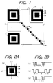
- Fig. 1 shows one embodiment of a two-dimensional code 1 in accordance with the present invention.
- This two-dimensional code 1 is a square having four apexes at its corners and comprises three isolated positioning symbols 2,2,2 placed at three corners of the two-dimensional code 1, a data region 3, a series of timing cells 4 diagonally extending in the data region 3, and an apex detecting cell 5 located at the remaining corner of the two-dimensional code 1.
- This two-dimensional code 1, a square code is constituted by the same number of vertical and lateral cells (21 cells x 21 cells). Each cell is the one selected from optically discriminable two kinds of cells, which are white (light) and black (dark) cells in the drawings and explanation in this embodiment.
- the timing cells 4 correspond to 1/1 inclined alternating light-and-dark cells.
- the apex detecting cell 5 acts as one of timing cells 4.
- Fig. 1 shows a blank condition where no data is described in the data region 3.
- the positioning symbols 2,2,2 are disposed at three of four corners of the two-dimensional code 1.
- the light and dark arrangement of cells in each positioning symbol 2 is characterized by a pattern consisting of a large square 2a of black cells, a middle square 2b of white cells concentric with but smaller in size than the large square 2a, and a small square 2c of black cells concentric with but smaller in size than the middle square 2b.
- Fig. 2 shows the scanning operation of this positioning symbol 2 and resultant light and dark signals.
- Fig. 2A shows representative three straight scanning lines (a),(b) and (c), each passing through the center of the positioning symbol with a distinctive angle.
- Fig. 2B shows signal waveforms corresponding to the light and dark patterns detectable along each of the scanning lines (a), (b) and (c), each frequency component ratio of which is identical with each other. More specifically, the frequency component ratio obtainable from each of the scanning lines (a), (b) and (c) passing through the center of the positioning symbol 2 is as follows:
- the characteristic frequency component ratio of the positioning symbol 2 is easily detectable by executing only one scanning operation in a predetermined direction. In other words, it is not necessary to repeatedly execute the scanning operation by changing the angle of the straight scanning line until the predesignated pattern is detected. Accordingly, the central position of the positioning symbol 2 can be easily and quickly found. Thus, the position of the two-dimensional code 1 is promptly identified, and the succeeding processing can be started immediately.
- the positioning symbol can be identified by only one scanning operation, it is no longer necessary to repeatedly change the angle of scan for making a judgement of whether the image taken from an image pickup device such as a TV camera includes various noises other than the two-dimensional code 1. Hence, the position of the two-dimensional code 1 is immediately recognized. In addition, all the necessary things to do after that is only to search the vicinity of thus found positioning symbol 2. Therefore, the code in the data region is speedily read out. Moreover, the means for detecting the specific frequency component ratio fits the hardware processing, which is executable in parallel with the image take-in processing by means of the TV camera etc. It means that the speed of reading out the code can be further increased.
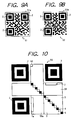
- FIG. 3 is a simple method of obtaining the contour of the two-dimensional code, realized by providing more than two positioning symbols 2 at corners of the code.
- Fig. 3A shows one example of a two-dimensional code 8 whose three corners are respectively provided a positioning symbol 2. If the central position of each of three positioning symbols 2, 2, 2 is found, it is possible to calculate the coordinates of three apexes of the two-dimensional code 8 based on the coordinates of the centers of the positioning symbols. Assuming that (x 0 , y 0 ), (x 1 , y 1 ) and (x 2 , y 2 ) represent the coordinates of the three apexes, the following equations 1 and 2 will obtain the coordinates (X 0 , Y 0 ) of the remaining apex. Thus, the contour of the two-dimensional code 8 is recognized.
- apex detecting cell 5 on an apex where the positioning symbol 2 is not disposed.
- the search will be conducted in the vicinity of the apex (X 0 , Y 0 ) obtained from the equations 1 and 2, to find out the apex detecting cell 5.
- the coordinates of the apex detecting cell 5 thus obtained as accurate apex coordinates (X 0 , Y 0 )
- the contour of the two-dimensional code is precisely obtained even if the two-dimensional code is unwantedly distorted. Needless to say, such an apex detecting cell 5 can be omitted if no distortion is expected.
- Fig. 3B shows an another two-dimensional code 9 in accordance with the present invention, which is characterized by two positioning symbols 2, 2 disposed at diagonal two corners of the two-dimensional code 9, whereas the two-dimensional code 8 of Fig. 3A includes three positioning symbols 2--2 disposed at three corners thereof. It will be preferable to additionally provide the apex detecting cell 5 in case of presence of distortion.
- the contour and an inclination ⁇ 2 of the two-dimensional code 9 are obtained from the following equations 4-8.
- a merit brought by this example is that the data ratio is increased.
- an orientation determining symbol 11 will be additionally required to determine the actual rotational position of the two-dimensional code 9.
- X 1 x 0 + x 2 - y 2 + y 0 2
- Y 1 y 0 + y 2 - x 0 + x 2 2
- X 3 x 0 + x 2 - y 0 + y 2 2
- Fig. 3C shows a two-dimensional code 13 in accordance with the present invention, which includes positioning symbols 2 disposed every corners of the two-dimensional code 13.
- This example is advantageous in that the contour of two dimensional code 13 is directly obtained even if the two-dimensional code 13 includes a significant distortion.
- An inclination ⁇ 3 is obtained from the definition tan -1 ( y 1 -y 0 /x 1 -x 0 ) .
- the data ratio is decreased.
- positioning symbols are disposed at all the corners, it is difficult to recognize the orientation of the code 13. For this reason, it is necessary to provide the orientation determining symbol 11 for identifying the orientation of the code 13.
- the timing cells 4, being alternating light and dark cells as shown in Fig. 1, have an arrangement of disposing white cells 4a and black cells 4b alternately so as to diagonally extend from one apex 1a of the two-dimensional code 1. That is, the timing cells 4 are arrayed with a 1/1 inclination (i.e. 45° inclination) in the data region 3 of the two-dimensional code 1.
- These timing cells 4--4 are used for accurately detecting the coordinates of each data cell. In other words, the density of image data is determined in accordance with intervals of these timing cells 4--4.
- Figs. 4A and 4B show representative arrangements of the timing cells 4.
- the timing cells 4 disclosed in Fig. 4A are arrayed diagonally from one apex P1 to the other apex P3 in such a manner that light and dark cells 4a and 4b are placed in an alternating manner so as to extend from the left top to the right bottom.
- the coordinates of each data cell in the data region 3 can be obtained using these timing cells 4.
- the coordinates of the center of each timing cell 4 is obtained.
- virtual lines i and j are drawn from the centers of timing cells 4 in vertical and lateral directions, each line being parallel to either side L1 or L2 of the two-dimensional code.
- the virtual lines i--i are laterally extending so as to pass through the coordinates of the centers of the timing cells 4--4, while the other virtual lines j--j are vertically extending so as to pass through the coordinates of the centers of the timing cells 4--4. Intersecting points formed by these virtual lines i--i and j--j are regarded as coordinates of each of data cells 4--4.
- the above-described method of obtaining the coordinates of each data cell using the timing cells 4 is advantageous in that error and affection of code distortion can be eliminated. Thus, the accuracy can be increased in the reading operation.
- Fig. 18 shows a conventional arrangement of the timing cells 4--4 which are disposed along two adjacent sides of the two-dimensional code.
- the number of timing cells 4 required for a 9x9 matrix is 17.
- the 9x9 matrix disclosed in Fig. 4A requires only 9 cells. In other words, the number of cells other than data cells can be reduced; therefore, the data ratio of two-dimensional code can be increased.
- the timing cells 4 can be diagonally arrayed from an intermediate portion of a side of the code.
- a series of timing cells 4 arrayed with an 1/1 inclination from an apex P13 can form intersecting points of virtual lines in the region R1, although the remaining region R2 has no intersecting points of virtual lines since it is only given one kind virtual lines (i.e. vertical lines only). It is of course possible to determine the coordinates of data cells in the region R2 based on these one kind virtual lines only. However, it is useful to provide another series of timing cells 4y in the region R2 for additionally forming lateral virtual lines, so that the coordinates of all the cells in the data region can be accurately identified.
- the data region 3 includes two protruding regions 3a and 3b where only one kind virtual lines (i.e. either vertical lines or lateral lines) are drawn.
- the area of such a protruding region is so small that accuracy is sufficiently assured without causing substantial problems.
- the protruding regions 3a and 3b are sandwiched between positioning symbols 2 and 2; therefore, it is technically possible to obtain intersecting points in such regions by drawing the other kind of virtual lines from each positioning symbol 2 based on light and dark pattern thereof. Thus, the coordinates are further accurately obtained.
- the data described in the data region 3 is generally encoded together with an error-correcting code restorable when it is contaminated by stain or the like and a CRC code for detecting an error.
- an error-correcting code restorable when it is contaminated by stain or the like
- a CRC code for detecting an error.
- burst error-correcting codes are suitable for stain or damage of the code.
- a Reed Solomon code is well known since it has an excellent error correcting efficiency.
- each character encoded by this kind of burst error-correcting code (which is expressed by a plurality of bits) is placed in the data cell region.
- Fig. 5 shows one example of such placement of a character. It is preferable that the cells 6a, each corresponding to a bit constituting part of a character, are summarized in a shape similar to a square without being dispersed.
- the example of Fig. 5 shows a group of nine cells (b0-b8) including eight bits dedicated to data of character and one bit dedicated to the parity.
- Figs. 6A and 6B illustrate the difference between a square (i.e. a two-dimensional) cell group and a linearly arrayed (i.e. a one- dimensional) cell group respectively representing a character, in order to explain that a two-dimensional code 21 including 3x3 square cell groups 6--6 is superior to a two-dimensional code 23 including 9 linearly arrayed cell groups 6--6 in view of readability under the presence of stain. More specifically, Fig. 6A shows a condition that a circular stain 16 adheres on the two-dimensional code 21 which consists of 3x3 square cell groups 6--6 each representing a character. In this case, the stain 16 is illustrated in a maximum size capable of suppressing the number of spoiled characters to be equal to only four. Fig.
- FIG. 6B shows a condition that another circular stain 16 is attached on the two-dimensional code 23 which consists of 9 linearly arrayed cell groups 6--6 piled up successively each representing a character.
- the stain 16 is illustrated in a maximum size capable of suppressing the number of spoiled characters to be equal to only four.
- a piece of stain 16a shown in Fig. 6C gives the same affection to the character cell groups 6--6 as that of a circular stain 16 having a diameter D. Accordingly, when the overall shape of the character cell groups 6--6 is arranged into a square (3 cells x 3 cells), the maximum diameter of the stain 16 only spoiling four character cell groups 6--6 is identical with the length of six consecutive cells as shown in Fig. 6A. On the other hand, when each character cell group 6 is arranged in a linear shape (1 cell x 9 cells), the maximum diameter of the stain 16 spoiling only four character cell groups 6--6 is identical with the length of four consecutive cells as shown in Fig. 6B.
- each character cell group 6 is advantageous in suppressing the number of spoiled characters as less as possible when the adverse affection by stain or damage is inevitable.
- the characters enter in an error-correcting region and easily read.
- data of each character are allocated in the cells within the data region 3.
- a predetermined character format either white or black is assigned to each cell 6a in each character cell group 6, thereby completing the pattern of the two-dimensional code 1.
- Fig. 7A shows a general binary encoding circuit using a comparator 30, which is speedy in operation and can respond to the change of brightness of the background.
- a follow-up waveform 32 approaches either a white or a black level of the input waveform 31 as shown in Fig. 7B when white cells or black cells are so consecutively and extensively arrayed.
- a resultant binary-encoded signal 33 has a width wider or narrower than the actual cell width.
- One is to provide dummy cells in the data region 3 and the character cell group 6 so as to be flexibly assigned to white or black depending upon the conditions.
- the other is to totally change the features of the cells according to a predetermined rule after white and black cells are placed in the data region 3. Either way will be practically adaptable, although the former method is disadvantageous in that the data ratio is lowered for provision of dummy cells.
- Fig. 8 shows, at upper left, a provisional two-dimensional code 41 including temporarily disposed data, and also shows, at upper center and right, two cell-feature-conversion matrix patterns 42a and 42b which are formed based on random number and certain regularity for changing cell features.
- the provisional two-dimensional code 41 is combined with each of the cell-feature-conversion matrix patterns 42a and 42b. More specifically, each cell on the provisional two-dimensional code 41 is reversed when its corresponding cell is a black cell 43a on the combined cell-feature-conversion matrix pattern 42a or 42b, while the features of the cell is not changed when its corresponding cell is a white cell 43b on the combined cell-feature-conversion matrix pattern 42a or 42b.
- the resultant pattern obtained from the above combination is identical with an exclusive-OR taken by the provisional two-dimensional code 41 and the cell-feature-conversion matrix pattern 42a or 42b.
- the above-described processing is executed with respect each of all the matrix patterns 42 prepared.
- a plurality of converted patterns 45 are obtained as much as the number of cell-feature-conversion matrix patterns prepared.
- a judgement is made as to whether white or black cells are arrayed consecutively and extensively and as to whether there happen to be a group of data cells having the same or similar frequency component ratio as that of the positioning symbol 2. From the result of this judgement, the most preferable data (i.e. an optimum placement pattern) is determined, thereby obtaining a finalized two-dimensional code 46.
- the left-hand pattern 45a is selected as an optimum placement pattern among plural patterns 45. By the way, this processing is only applied to the data region 3.
- two-dimensional code 46 Decoding operation of two-dimensional code 46 will be immediately carried out if the number of the cell-feature-conversion matrix patterns 42 is only one. However, when a plurality of matrix patterns 42 are used as described above, it is definitely necessary to find out the cell-feature-conversion matrix pattern 42 used for creating the finalized two-dimensional code 46. Thus, it is useful that the two-dimensional code 46 stores an information data 47 indicating the type of the conversion matrix pattern 42 used in the conversion processing for obtaining the two-dimensional code 46. If such an information data 47 is included, the data cells can be easily converted or reconstructed into their original pattern by taking an exclusive-OR between the corresponding cell-feature-conversion matrix pattern 42 and the two-dimensional code 46.
- Fig. 9A shows an example of dummy black line 51a surrounding all the outer periphery of the two-dimensional code 51, so that the binary-encoding operation for the positioning symbols 2--2 and outer peripheral data cells of the two-dimensional code 51 can be accurately carried out.
- the outer periphery of the two-dimensional code is a margin; therefore, it is feared that the outermost black cells in the positioning symbol 2 and the black data cells on the outer periphery cannot be accurately binary encoded as previously explained with reference to Fig. 7.
- surrounding the outer periphery of the two-dimensional code 51 by the dummy black line 51a is useful to increase the accuracy in the binary-encoding operation of the black cells in the positioning symbols 2 and in the outer peripheral region.
- the positioning symbols 2 are specially important for identifying the position of the matrix; therefore, it is preferable to provide dummy black lines 52a dedicated only to each positioning symbol 2 as shown in Fig. 9B, so that at least the frequency component of each positioning symbol is accurately detected and precisely binary encoded.
- the reading operation is easily disabled by simply drawing a line 131 across a bar code 130 as shown in Fig. 19.
- the length of a required nullifying line will be fairly long due to its two-dimensional arrangement. If the error-correcting code is involved as described above, drawing such a line is no longer effective to completely disable the two-dimensional code.
- a code-reading-prohibition cell 58 in the two-dimensional code 55.
- a reading device is prohibited to execute a reading operation. That is, the code-reading-prohibition cell 58 is checked prior to the decoding operation, and the decoding operation is prohibited when the cell 58 is black.
- the two-dimensional code 55 may include an important information 59 or a cell-feature-conversion matrix pattern information 7.
- an important information 59 or a cell-feature-conversion matrix pattern information 7 In view of adverse affection by stain, damage or brightness change of the background, it is preferable to dispose the same information 59a and 7a at different positions spaced from these information 59 and 7.
- this arrangement allows the reading device to read at least the other information (i.e. non-spoiled one), thereby assuring the reading operation of the important information 59 or 59a and the cell-feature-conversion matrix pattern information 7 or 7a.
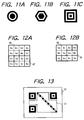
- the positioning symbol 2 can be constituted by concentric circles as shown in Fig. 11A, or concentric hexagons as shown in Fig. 11B, or any other concentric polygons.
- any concentric similar figures overlapped successively can be used as positioning symbol 2.
- the similar figures can be overlapped more as shown in Fig. 11C.
- the two-dimensional code 1 having a square contour
- the square contour can be replaced by a rectangular contour.
- a laterally elongated shape will be generally preferable as shown by a two-dimensional code 71 in Fig. 13, since such a shape well meets the lateral and vertical resolutions.
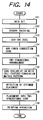
- Step 101 data are set in a work memory (Step 101). Then, objective data are binary encoded into "0" or “1” to form a two-dimensional code (Step 102). Subsequently, an error detecting code (CRC) and an error-correcting code are attached to the data (Steps 103 and 104) . Thereafter, these data are arranged in a two-dimensional pattern according to a predetermined rude (Step 105). Next, an exclusive-OR is taken by the resultant data pattern and each of cell-feature-conversion matrix patterns prepared beforehand (Step 106). Then, an optimum placement pattern is selected among resultant patterns (Step 107). After that, the optimum placement pattern is placed in the two-dimensional code (Step 108). Then, the printing operation is executed (Step 109).
- CRC error detecting code
- Step 105 an exclusive-OR is taken by the resultant data pattern and each of cell-feature-conversion matrix patterns prepared beforehand
- Step 106 an optimum placement pattern is selected among resultant patterns
- a CCD camera 500a takes an image of cells in a two-dimensional code 81, then converts the image into analog or digital signals pixel by pixel in response to light intensity of the image, and successively outputting resultant image signals.
- the pixel corresponds to each cell of the two-dimensional code 81.
- a decoder 500 comprising a CPU, a ROM, a RAM and an I/O unit, decodes the image signals of the two-dimensional code 81 into binary-coded signals, as shown in Fig. 17.
- the image signals produced from the CCD camera 500a are binary encoded (Step 300) in accordance with a level of each signal, thereby successively producing binary-coded signals.
- the binary-coded image signals are successively stored into a memory (RAM) as an image data every pixel through a hardware processing (Step 310).
- the coordinates of the positioning symbols 2 are detected based on the binary-coded image signals (Step 320). Namely, the specific pattern (i.e. the frequency component ratio of Fig. 2B) corresponding to the positioning symbol 2 is searched based on the binary-coded signals.
- Step 330 a judgement is made as to whether more than three positioning symbols 2--2 are found or not. Namely, the coordinates of each symbol 2 is obtained from the image data stored in the memory means (RAM) based on the detection of the specific pattern (Fig. 2B). The procedure of this flow chart does not proceed to the next step unless it completely detects all of three positioning symbols 2--2 of the two-dimensional code 81. Accordingly, when three positioning symbols are not found, the procedure returns to the step 300 to repeat the reading operation of image again. It may happen that a total of four positioning symbols 2--2 are detected at a time. This is believed that a confusing pattern having exactly the same frequency component ratio as that of the positioning symbol 2 exists in the data region of the two-dimensional code 81 or in a region outside the two-dimensional code 81.
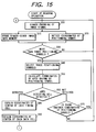
- Step 340 three of thus found positioning symbols 2--2, although they are mere candidates of positioning symbols 2--2 at this moment, are selected (Step 340). Then, the coordinates of an apex having no positioning symbol 2 is calculated (Step 350). Thereafter, a judgement is made as to whether the apex detecting cell 5 is found at the position obtained in the step 350 (Step 360) . If the apex detecting cell 5 is not detected, it is considered that selection and combination were improper. Thus, the next judgement is made as to whether there is another possible combination of the positioning symbols 2--2 (Step 370). If the answer is YES, the procedure returns to the step 340 to change the combination of the positioning symbols 2--2. If the apex detecting cell 5 is not found (i.e. "NO" in the step 370) as a result of repetitive detections based on any possible selection and combination, then the procedure returns to the step 300 to restart the binary-encoding processing of the image signals.
- the coordinates of a center of each timing cell 4 are obtained by detecting the alternately extending light and dark timing cells 4--4 one after another along a diagonal from the apex detecting cell 5 (Step 380). Then, virtual lines are drawn from the centers of these timing cells 4--4, thereby obtaining the coordinates of a center of each data cell (Step 390).
- a white-and-black pattern of the data cells is judged based on the image data (step 400).
- the cell-feature-conversion matrix pattern information 7 is read (Step 410). More specifically, the cell-feature-conversion matrix pattern is read out from the ROM, RAM or an external memory device not shown. Subsequently, an exclusive-OR is taken between thus readout conversion matrix pattern and the data cell pattern judged in the step 400, thereby restoring the content of the data cells (Step 420).
- steps 410 and 420 can be omitted when the cell features of the two-dimensional code is not converted.
- Step 430 the data region is divided into individual character cell groups. It is needless to say that division is executed in accordance with the placement of character cell groups as shown in Figs. 6A and 6B or Figs. 12A and 12B.
- Step 440 Individual data involved in each character cell group are converted into a corresponding character.
- Step 450 a judgement is made as to whether error is detected based on the error-correcting code. If any error is found, the error correction of data is executed (Step 460). When no error is found in the step 450 or after the error correction of data is finished, another judgement is made as to whether any error is found based on the error detecting code (i.e. CRC code) (Step 470). If no error is found, the procedure is terminated. If any error is found, the procedure returns to the step 300 to restart all the processing from the beginning.
- CRC code error detecting code
- the resultant data are transmitted to a host computer (not shown) wherein a predetermined control is executed based on these data.
- the positioning symbol assures the same characteristic frequency component ratio to be obtained irrespective of the orientation of a straight scanning line. Hence, it is not necessary to repeat the scanning operation changing its scanning angle.
- the matrix at least two predetermined positions are quickly and easily detected. Once the positions of the predetermined two positions are detected in the matrix, the position and a rotational angle of the whole matrix is easily calculated based on the distance and angle between them.
- the predetermined positions When the predetermined positions are apexes of the matrix, they will be immediately found in the scanning search, and are seldom disturbed by other code patterns when they are searched.
- the shape of the matrix is generally a square or a rectangle.
- a preferable shape of the positioning symbol is a square or a rectangle since it fits to the shape of the matrix and loss of space can be suppressed at a minimum level.
- a square is most preferable since it assures a least loss.
- the matrix includes a series of light and dark cells alternately extending with an inclination 1/1, the number of cells used for the alternating light-and-dark cells can be fairly reduced. Thus, the remaining cells can be effectively used for a space available for other useful information.
- the data cells can be converted into a pattern discriminable from the characteristic patterns of the positioning symbols and the 1/1 inclined alternating light-and-dark cells. It will facilitate the discrimination of the data cells from the positioning symbols and the 1/1 inclined alternating light-and-dark cells.
- the processing will become simple and speedy.
Landscapes
- Physics & Mathematics (AREA)
- Engineering & Computer Science (AREA)
- Health & Medical Sciences (AREA)
- Electromagnetism (AREA)
- General Health & Medical Sciences (AREA)
- Toxicology (AREA)
- Artificial Intelligence (AREA)
- Computer Vision & Pattern Recognition (AREA)
- General Physics & Mathematics (AREA)
- Theoretical Computer Science (AREA)
- Image Analysis (AREA)
- Image Processing (AREA)
Description
Claims (10)
- A two-dimensional code, comprising:cells (b0-b8) each representing a binary-coded data,said cells being placed on a two-dimensional matrix (1) as a pattern which is readable by a scanning operation along a predetermined scanning line; characterized in thatat least two positioning symbols (2) are disposed at predetermined positions in said matrix, each of said positioning symbols (2) having a pattern capable of producing a waveform having an identical element width ratio irrespective of any orientation of said scanning line when said scanning line passes through the center of each positioning symbol.
- The two-dimensional code in accordance with claim 1, wherein said predetermined positions are apexes of said two-dimensional matrix (1).
- The two-dimensional code in accordance with claim 1 or 2, wherein each said positioning symbol has a pattern including concentric similar figures (2a, 2b and 2c) of decreasing size overlapped successively.
- The two-dimensional code in accordance with claim 1, further comprising a series of timing cells (4) including alternate light and dark cells (4a and 4b), said series having an inclination of 45° in said two-dimensional matrix (1).
- The two-dimensional code in accordance with claim 1, wherein said binary-coded data includes a plurality of characters (6), and each of said characters is represented by a group of cells (6a) disposed in a two-dimensional region (3) in said matrix (1).
- The two-dimensional code in accordance with claim 1, further comprising an apex detecting cell (5) disposed on an apex of said two-dimensional matrix (1) where none of said positioning symbols is disposed.
- A two-dimensional code reading apparatus for optically reading the two-dimensional code defined in claim 1, said reading apparatus comprising:an image pickup device (500a) taking an image of said two-dimensional code (81), then converting the image into image signals pixel by pixel in response to light intensity of the image, and successively outputting resultant image signals; anda decoder unit (500) decoding said resultant image signals into binary-coded signals;
wherein said decoder unit (500) comprises:binary-encoding means (CPU; Step 300) for binary encoding said image signals in accordance with a level of each signal, and outputting binary-coded signals successively;memory means (RAM) for storing said binary-coded signals as image data in accordance with a position of a pixel where the image was taken;symbol detecting means (CPU; Step 320) for detecting the specific pattern corresponding to each of said positioning symbols (2) based on said binary-coded signals and detecting the coordinates of each of said symbols (2) from the image data stored in said memory means (RAM) based on said detected specific pattern;matrix position determining means (CPU; Steps 340-390) for finalizing a contour and an orientation of said two dimensional matrix based on the coordinates of the symbols (2) detected by said symbol detecting means, thereby identifying all the coordinates of said binary-coded cells placed on the two-dimensional matrix; andreading means (CPU; Step 400-470) for reading out said image data stored in said memory means (RAM) in accordance with the finalized contour and orientation of said two dimensional matrix. - The two-dimensional code reading apparatus in accordance with claim 7, whereinsaid two-dimensional code (81) comprises a series of timing cells (4) including alternate light and dark cells (4a and 4b) arranged in said matrix (1), optically readable by said image pickup device (500a); andsaid decoder unit (500) further comprises timing cell detecting means (CPU; Step 280) for detecting coordinates of each timing cell (4) from the image data stored in said memory means (RAM) in accordance with the coordinates of said symbols (2) obtained by said symbol detecting means (CPU; Step 320), said timing cells (4) determining the density of the image data in accordance with the intervals of the timing cells.
- The two-dimensional code reading apparatus in accordance with claim 7, whereinsaid two-dimensional code (81) is created by performing an exclusive-OR operation cell by cell between a predetermined provisional two dimensional code (41) and a two-dimensional cell-feature conversion code (42) which includes a specific conversion pattern represented by light and dark cells corresponding to the data region of said provisional two-dimensional code (41); andsaid reading means (CPU; Step 400-470) restores the information of said provisional two-dimensional code (41) by performing an exclusive-OR operation cell by cell between the two-dimensional image data obtained from said image pickup means (500a) and two-dimensional image data of said two-dimensional cell-feature-conversion code (42) stored in said memory means (RAM).
- A two-dimensional code reading method for optically reading the two-dimensional code defined in claim 1, comprising the steps of:taking an image of said two-dimensional code (81) by an image pickup device (500a), then converting the image into image signals pixel by pixel in response to light intensity of the image, and binary encoding (Step 300) said image signals in accordance with a level of each signal, then storing (Step 310) thus binary-coded signals as image data in a memory means (RAM) in accordance with a position of a pixel where the image was taken;detecting (Step 320) the specific pattern corresponding to each of said positioning symbols (2) based on said binary-coded signals, as a parallel processing to said step (Step 310) of storing the binary-coded signals in the memory means (RAM);detecting (Step 320) coordinates of each of said symbols (2) from the image data stored in said memory means (RAM) based on the detection of said specific pattern;finalizing (Steps 340-390) a contour and an orientation of said two-dimensional matrix based on the coordinates of the symbols (2), thereby identifying all the coordinates of said binary-coded cells placed on the two-dimensional matrix; andreading out (Step 400-470) said image data stored in said memory means (RAM) in accordance with the finalized contour and orientation of said two-dimensional matrix.
Applications Claiming Priority (3)
| Application Number | Priority Date | Filing Date | Title |
|---|---|---|---|
| JP4258794A JP2938338B2 (en) | 1994-03-14 | 1994-03-14 | Two-dimensional code |
| JP42587/94 | 1994-03-14 | ||
| JP4258794 | 1994-03-14 |
Publications (2)
| Publication Number | Publication Date |
|---|---|
| EP0672994A1 EP0672994A1 (en) | 1995-09-20 |
| EP0672994B1 true EP0672994B1 (en) | 2000-07-26 |
Family
ID=12640203
Family Applications (1)
| Application Number | Title | Priority Date | Filing Date |
|---|---|---|---|
| EP95103511A Expired - Lifetime EP0672994B1 (en) | 1994-03-14 | 1995-03-10 | Method and apparatus for reading an optically two-dimensional code |
Country Status (3)
| Country | Link |
|---|---|
| EP (1) | EP0672994B1 (en) |
| JP (1) | JP2938338B2 (en) |
| DE (1) | DE69518098T2 (en) |
Cited By (10)
| Publication number | Priority date | Publication date | Assignee | Title |
|---|---|---|---|---|
| WO2005096219A1 (en) * | 2004-04-02 | 2005-10-13 | Silverbrook Research Pty Ltd | Surface having disposed therein or thereon coded data |
| WO2013100851A2 (en) | 2011-12-29 | 2013-07-04 | Delaval Holding Ab | Pairing of a mobile terminal with a farm control and monitoring system |
| EP2701099A1 (en) | 2012-08-24 | 2014-02-26 | I4pack GmbH | Computer network for dynamically controlling qr-codes |
| WO2014074057A1 (en) | 2012-11-07 | 2014-05-15 | Delaval Holding Ab | Methods, arrangements and devices for animal management |
| EP2782060A1 (en) | 2013-03-19 | 2014-09-24 | Usual Q Smart S.L. | Purchasing method and system for purchasing by means of two-dimensional graphic codes |
| US9355293B2 (en) | 2008-12-22 | 2016-05-31 | Canon Kabushiki Kaisha | Code detection and decoding system |
| DE102016200388A1 (en) | 2016-01-14 | 2017-07-20 | Tridonic Gmbh & Co Kg | System for generating position information, corresponding method and mobile device and server for generating position information |
| WO2017144291A1 (en) | 2016-02-26 | 2017-08-31 | Robert Bosch Gmbh | Localization system and method |
| EP3242252A1 (en) | 2016-05-06 | 2017-11-08 | Doris Renate Purzer | Multi-dimensional graphical code |
| WO2023174799A1 (en) | 2022-03-16 | 2023-09-21 | Dataqon Gmbh | Service provider-customer communication system comprising central data storage and data management, integrated and synchronized time-tracking system, and local terminals |
Families Citing this family (122)
| Publication number | Priority date | Publication date | Assignee | Title |
|---|---|---|---|---|
| WO1994008314A1 (en) * | 1992-09-28 | 1994-04-14 | Olympus Optical Co., Ltd. | Dot code and information recording/reproducing system for recording/reproducing dot code |
| JP3568374B2 (en) * | 1992-09-28 | 2004-09-22 | オリンパス株式会社 | Dot code and information reproduction system |
| JP2867904B2 (en) * | 1994-12-26 | 1999-03-10 | 株式会社デンソー | 2D code reader |
| JP3448120B2 (en) | 1994-12-27 | 2003-09-16 | シャープ株式会社 | Digital information record carrier |
| JP3668275B2 (en) * | 1995-03-15 | 2005-07-06 | シャープ株式会社 | Digital information recording method, decoding method and decoding device |
| JP3655661B2 (en) * | 1995-03-31 | 2005-06-02 | シャープ株式会社 | Digital information record carrier and digital information reading method using the same |
| US5862270A (en) * | 1995-12-08 | 1999-01-19 | Matsushita Electric Industrial Co., Ltd. | Clock free two-dimensional barcode and method for printing and reading the same |
| JP3209108B2 (en) * | 1996-08-23 | 2001-09-17 | 松下電器産業株式会社 | 2D code reader |
| JPH10326331A (en) | 1997-03-24 | 1998-12-08 | Olympus Optical Co Ltd | Recording medium with dot code, and code reader |
| US6267296B1 (en) | 1998-05-12 | 2001-07-31 | Denso Corporation | Two-dimensional code and method of optically reading the same |
| US6201901B1 (en) * | 1998-06-01 | 2001-03-13 | Matsushita Electronic Industrial Co., Ltd. | Border-less clock free two-dimensional barcode and method for printing and reading the same |
| JP4122629B2 (en) | 1998-09-03 | 2008-07-23 | 株式会社デンソー | 2D code generation method |
| JP3458737B2 (en) | 1998-11-27 | 2003-10-20 | 株式会社デンソー | Reading method of two-dimensional code and recording medium |
| US6601772B1 (en) * | 2000-07-14 | 2003-08-05 | Intellidot Corporation | Compact matrix code and one-touch device and method for code reading |
| US6722567B2 (en) | 2001-06-07 | 2004-04-20 | Hewlett-Packard Development Company, L.P. | Generating and decoding graphical bar codes |
| US7082225B2 (en) | 2001-08-28 | 2006-07-25 | Nippon Telegraph And Telephone Corporation | Two dimensional image recording and reproducing scheme using similarity distribution |
| DE10220220C1 (en) * | 2002-02-18 | 2003-05-22 | Tropf Hermann | Localization device for optically-readable code or text uses localization pattern with at least four 2-dimensional elements of 2 different types |
| JP4208481B2 (en) * | 2002-04-30 | 2009-01-14 | トッパン・フォームズ株式会社 | Two-dimensional code reading method, two-dimensional code reading system, and article with a two-dimensional code used therein |
| KR100414524B1 (en) * | 2002-10-31 | 2004-01-16 | 주식회사 아이콘랩 | Two-dimensional Code having superior decoding property which is possible to control the level of error correcting codes, and method for encoding and decoding the same |
| AU2003227506A1 (en) | 2003-04-15 | 2004-11-04 | Fujitsu Limited | Code recognizing method and device |
| US7938330B2 (en) | 2003-05-02 | 2011-05-10 | Yutaka Kiuchi | Methods and execution programs for reading and displaying a two-dimensional code |
| JP4180497B2 (en) | 2003-12-05 | 2008-11-12 | 富士通株式会社 | Code type discrimination method and code boundary detection method |
| AU2003292671A1 (en) * | 2003-12-26 | 2005-08-12 | Mitsui And Associates Telepark Corp. | Two-dimensional bar code system, two-dimensional bar code generating method and computer program |
| JP4576146B2 (en) | 2004-04-02 | 2010-11-04 | 富士通株式会社 | Specific image position estimation device |
| JP2005316755A (en) * | 2004-04-28 | 2005-11-10 | Nec Electronics Corp | Two-dimensional rectangular code symbol reader and two-dimensional rectangular code symbol reading method |
| KR100858399B1 (en) | 2004-10-15 | 2008-09-11 | 가부시키가이샤 소니 컴퓨터 엔터테인먼트 | Object, image data, image data transmission method, card, game mat, card game system, image analysis device, and image analysis method |
| EP1947605B1 (en) * | 2005-02-25 | 2019-03-06 | Psion Systems Inc. | Automatic perspective distortion detection and correction for document imaging |
| JP4088300B2 (en) | 2005-06-01 | 2008-05-21 | 富士通株式会社 | Image area detection apparatus, image area detection method, and image area detection program |
| JP4098313B2 (en) | 2005-06-02 | 2008-06-11 | 富士通株式会社 | Image processing device |
| EP1916619B1 (en) | 2005-07-22 | 2011-05-25 | Content Idea of Asia Co., Ltd. | Hierarchized two-dimensional code, creation method thereof, and read method thereof |
| JP2007066377A (en) | 2005-08-30 | 2007-03-15 | Sony Corp | Recorder, recording method and hologram recording medium |
| KR100828539B1 (en) | 2005-09-20 | 2008-05-13 | 후지제롯쿠스 가부시끼가이샤 | Detection method of two dimensional code, detection device thereof, and storage medium having detection program storaged therein |
| JP4665710B2 (en) * | 2005-10-21 | 2011-04-06 | 株式会社デンソーウェーブ | Information code carrier |
| CN101341472A (en) | 2005-12-20 | 2009-01-07 | 技术基础逻辑有限公司 | Information authentication gateway, information acquisition system and method using the same |
| JP4911340B2 (en) | 2006-02-10 | 2012-04-04 | 富士ゼロックス株式会社 | Two-dimensional code detection system and two-dimensional code detection program |
| US8050502B2 (en) | 2006-06-21 | 2011-11-01 | Namco Bandai Games Inc. | Two-Dimensional code generation method, two-dimensional code, two-dimensional code recognition method, and image recognition device |
| WO2008053545A1 (en) | 2006-10-31 | 2008-05-08 | Fujitsu Limited | Image encryption/decryption device, method and program |
| ES2823232T3 (en) | 2007-01-23 | 2021-05-06 | Nec Corp | Marker generation system and method |
| WO2008134804A1 (en) * | 2007-05-03 | 2008-11-13 | Kevin Loughrey | Large number id tagging system |
| JP4348381B2 (en) | 2007-05-30 | 2009-10-21 | 富士通株式会社 | Image encryption / decryption device, method and program |
| JP5491860B2 (en) | 2007-05-31 | 2014-05-14 | 株式会社Pfu | Electronic document encryption system, program and method |
| CN101652987B (en) | 2007-05-31 | 2011-09-14 | 株式会社Pfu | Paper media information encryption system, decryption system and method for the same |
| US8542867B2 (en) | 2007-07-31 | 2013-09-24 | Canon Kabushiki Kaisha | Image processing for reproducing code image from original information |
| JP2009130725A (en) * | 2007-11-26 | 2009-06-11 | Nippon Telegr & Teleph Corp <Ntt> | Visible light communication system and optical receiving device therefor |
| JP5206024B2 (en) | 2008-02-28 | 2013-06-12 | 富士通株式会社 | Image decryption device, image encryption device, image decryption method, and image decryption program |
| US8430329B2 (en) | 2008-03-14 | 2013-04-30 | Yutaka Kiuchi | Two-dimensional code publishing program and two-dimensional code decoding program |
| JP5071188B2 (en) | 2008-03-24 | 2012-11-14 | 富士通株式会社 | Image encryption / decryption device and program |
| JP5120156B2 (en) | 2008-03-27 | 2013-01-16 | 株式会社デンソーウェーブ | 2D code |
| JP5136302B2 (en) | 2008-03-27 | 2013-02-06 | 株式会社デンソーウェーブ | Two-dimensional code, two-dimensional code generation method, computer-readable program for displaying two-dimensional code, authentication method using two-dimensional code, and information providing method using two-dimensional code |
| JP5192039B2 (en) | 2008-05-29 | 2013-05-08 | 株式会社Pfu | Electronic document processing system, method and program |
| JP5168124B2 (en) * | 2008-12-18 | 2013-03-21 | 富士通株式会社 | Image marker adding apparatus, method, and program |
| JP5110202B2 (en) | 2009-03-19 | 2012-12-26 | 富士通株式会社 | Marker generation program, restoration program, marker generation device, restoration device, and marker generation method |
| JP5447235B2 (en) | 2009-07-31 | 2014-03-19 | セイコーエプソン株式会社 | Marker processing method, marker processing apparatus, and marker processing program |
| JP5321352B2 (en) | 2009-08-27 | 2013-10-23 | 富士ゼロックス株式会社 | Two-dimensional code generation apparatus, image forming system, two-dimensional code reading apparatus, computer program, and medium |
| JP5505007B2 (en) | 2010-03-18 | 2014-05-28 | 富士通株式会社 | Image processing apparatus, image processing method, and computer program for image processing |
| JP5560887B2 (en) | 2010-05-10 | 2014-07-30 | 富士ゼロックス株式会社 | Image processing apparatus and image processing program |
| CN102959936B (en) | 2010-06-25 | 2015-05-06 | 富士通株式会社 | Image processing device and image processing method |
| GB201014408D0 (en) * | 2010-08-31 | 2010-10-13 | Swipe Pay Ltd | Improvements in and relating to mobile communication devices |
| WO2012127578A1 (en) | 2011-03-18 | 2012-09-27 | 富士通株式会社 | Image-processing device, image-processing method, and image-processing computer program |
| WO2012127639A1 (en) | 2011-03-22 | 2012-09-27 | 富士通株式会社 | Image-processing device and image-processing method |
| WO2013032451A1 (en) * | 2011-08-30 | 2013-03-07 | Hewlett-Packard Development Company, L.P. | Identifying user-target relation |
| GB2496415A (en) * | 2011-11-10 | 2013-05-15 | Skype | An image data decoding method for decoding contact information and communication event related to a second user and implementing the communication event |
| JP5586705B2 (en) | 2012-07-05 | 2014-09-10 | 株式会社東芝 | Apparatus and method for embedding data in object, and apparatus and method for extracting embedded data |
| US9436852B2 (en) | 2012-08-17 | 2016-09-06 | A.T. Communications Co., LTD | Two-dimensional code authenticating device, two-dimensional code generating device, two-dimensional code authenticating method, and program |
| WO2014054254A1 (en) * | 2012-10-04 | 2014-04-10 | Sintokogio, Ltd. | System for inspecting equipment |
| JP6115750B2 (en) * | 2012-10-25 | 2017-04-19 | 株式会社デンソーウェーブ | Image recognition system, image recognition method, and portable terminal |
| JP5743994B2 (en) * | 2012-10-26 | 2015-07-01 | 東京書籍株式会社 | Printed matter displaying two-dimensional code |
| KR101801217B1 (en) | 2012-11-13 | 2017-11-24 | 교도 인사쯔 가부시키가이샤 | Two-dimensional code |
| WO2014077186A1 (en) | 2012-11-13 | 2014-05-22 | 共同印刷株式会社 | Two-dimensional code, system for creation of two-dimensional code, and analysis program |
| SG11201503742XA (en) * | 2012-11-13 | 2015-06-29 | Kyodo Printing Co Ltd | Two-dimensional code |
| ITAN20130029A1 (en) | 2013-02-15 | 2014-08-16 | Soundreflections Di Polzoni Andrea | SYSTEM AND METHOD TO GENERATE ELEMENTS CONTAINING QUICK RESPONSE CODES |
| WO2015001637A1 (en) * | 2013-07-03 | 2015-01-08 | A・Tコミュニケーションズ株式会社 | Authentication server, authentication system, authentication method, and program |
| WO2015008102A1 (en) | 2013-07-19 | 2015-01-22 | Niss Group Sa | System and method for indentifying and authenticating a tag |
| JP6148976B2 (en) * | 2013-12-18 | 2017-06-14 | 株式会社ミマキエンジニアリング | Boundary determination method and media cutting method |
| JP5984863B2 (en) * | 2014-01-29 | 2016-09-06 | 京セラドキュメントソリューションズ株式会社 | Image processing device |
| GB2523136A (en) * | 2014-02-13 | 2015-08-19 | Coolio Ltd | A method and apparatus for encoding and decoding digital data in an image |
| EP3144857B1 (en) | 2014-05-14 | 2021-10-13 | Kyodo Printing Co., Ltd. | Two-dimensional code, two-dimensional-code analysis system, and two-dimensional-code generation system |
| EP3144856B1 (en) | 2014-05-14 | 2021-02-24 | Kyodo Printing Co., Ltd. | Two-dimensional code, and two-dimensional-code analysis system |
| JP6486016B2 (en) * | 2014-05-16 | 2019-03-20 | 株式会社デンソーウェーブ | Information code generation method, information code, and information code utilization system |
| EP2975556A1 (en) | 2014-07-18 | 2016-01-20 | NISS Group SA | System and method for identifying and authenticating ammunition |
| DE102015000135A1 (en) | 2015-01-07 | 2016-07-07 | Martin Eberlein | Method for lending a means of transport suitable for a shopping process and means of transport for carrying out this method |
| DE102015002782A1 (en) | 2015-03-06 | 2016-09-08 | Grohe Ag | Sanitary fitting with sensor |
| CN105117677B (en) * | 2015-07-30 | 2017-10-31 | 福建联迪商用设备有限公司 | A kind of QR codes characteristic detection method and system |
| EP3332927B1 (en) | 2015-08-05 | 2024-07-24 | Horizon International Inc. | Sheet processing device and method for controlling same |
| JP6233734B2 (en) | 2015-09-01 | 2017-11-22 | 合同会社IP Bridge1号 | Reading device, information processing method, information processing device, program, recording medium, ink, pigment, and storage device |
| CN105095822B (en) * | 2015-09-07 | 2018-07-06 | 福建联迪商用设备有限公司 | A kind of Chinese letter co pattern image detection method and system |
| US20190147206A1 (en) * | 2015-09-15 | 2019-05-16 | Dai Nippon Printing Co., Ltd. | Information storage device and information readout device |
| DE102015013001A1 (en) | 2015-10-07 | 2017-04-13 | Carsten Engel | Method for connecting analog objects to a digital storage unit |
| JP6927559B2 (en) | 2015-12-17 | 2021-09-01 | 株式会社テララコード研究所 | Optical code, optical code creation method, optical code authenticity determination method, optical code reader, and reading aid |
| DE102015226684A1 (en) | 2015-12-23 | 2017-07-13 | 1112tag.com UG (haftungsbeschränkt) | A method for providing access to digital resources on a mobile device, and corresponding computer program product, mobile device, server, and device |
| JP6465051B2 (en) | 2016-03-04 | 2019-02-06 | 株式会社デンソーウェーブ | Information code and information code reading method |
| JP2018001333A (en) * | 2016-06-30 | 2018-01-11 | セイコーエプソン株式会社 | Calibration board, robot and detection method |
| MA39233B1 (en) | 2016-07-27 | 2018-11-30 | Univ Abdelmalek Essaadi Tetouan | Method for remote identification of the qr code by means of a camera. |
| DE102017006616A1 (en) | 2016-08-31 | 2018-03-01 | Sew-Eurodrive Gmbh & Co Kg | Situation tracking system and position sensing system |
| IT201700014359A1 (en) | 2017-02-09 | 2018-08-09 | Aitek S P A | Anti-counterfeiting bar code, system and method for generating and authenticating a security based on this code |
| JP6880903B2 (en) * | 2017-03-27 | 2021-06-02 | 横浜ゴム株式会社 | Expiration date notification device and method for puncture repair liquid |
| JP2019021165A (en) * | 2017-07-20 | 2019-02-07 | 株式会社デンソーウェーブ | Two-dimensional code and two-dimensional code reading device |
| DE102017131239A1 (en) | 2017-12-22 | 2019-06-27 | Eckart Neuhaus | Centralized collection of clinical and non-clinical measurements in hospital, nursing home and other care facilities |
| JP6473899B1 (en) | 2017-12-29 | 2019-02-27 | 株式会社I・Pソリューションズ | Composite code pattern, generating device, reading device, method and program |
| DE102018200574A1 (en) | 2018-01-15 | 2019-07-18 | Zf Friedrichshafen Ag | Parking system for the detection and management of occupied and unoccupied parking stands |
| WO2019171560A1 (en) | 2018-03-08 | 2019-09-12 | mui Lab株式会社 | Display method and display device for two-dimensional code |
| JP6562136B2 (en) * | 2018-08-02 | 2019-08-21 | 株式会社デンソーウェーブ | Information code generation method, information code, and information code utilization system |
| KR102219751B1 (en) | 2019-01-21 | 2021-02-24 | 주식회사 머니브레인 | Method for authenticating a normalized pattern based on a block chain with a merkle tree structure and apparatus thereof |
| CN111507120A (en) * | 2019-01-31 | 2020-08-07 | 北京骑胜科技有限公司 | Two-dimensional code positioning frame identification method and device, electronic equipment and storage medium |
| DE102019202636B4 (en) | 2019-02-27 | 2023-11-16 | Zf Friedrichshafen Ag | Marking object that can be arranged on a vehicle child seat for adaptively triggering an impact cushion, method for determining a position and/or orientation of a vehicle child seat relative to a vehicle seat and computer program product for adaptively triggering an impact cushion |
| US11574330B2 (en) | 2019-04-26 | 2023-02-07 | Drum Technologies, Inc. | Distributed system to enable dynamic, on-demand sales force with merchant, seller and buyer networked |
| EP3731163A1 (en) * | 2019-04-26 | 2020-10-28 | Drum Technologies, Inc. | System and method for dynamic, on-demand sales force and offer dissemination |
| DE102020002676B3 (en) | 2020-05-05 | 2021-03-25 | Sew-Eurodrive Gmbh & Co Kg | Mobile transport system |
| IT202000013516A1 (en) | 2020-06-08 | 2021-12-08 | Mario Piccioni | DIGITAL MAILBOX WITH BIOMETRIC TECHNOLOGY |
| DE202020005824U1 (en) | 2020-06-17 | 2022-08-22 | Maximilian Knöfel | System for providing and passing on specific information about a person and/or thing |
| DE102020115928A1 (en) | 2020-06-17 | 2021-12-23 | Maximilian Knöfel | System for providing and passing on specific information about a person and / or thing |
| JP7351265B2 (en) * | 2020-06-26 | 2023-09-27 | 株式会社豊田自動織機 | Recognition device and recognition method |
| DE102020125901A1 (en) | 2020-10-02 | 2022-04-07 | Nishi Notani | Flexible display unit with electronic paper and solar foil |
| DE102020129339A1 (en) | 2020-11-06 | 2022-05-12 | Windmöller & Hölscher Kg | Process for automatic error management on a printing press |
| CN112414225A (en) * | 2020-11-13 | 2021-02-26 | 中国船舶重工集团公司第七0七研究所 | Target combining two-dimensional code and circular coding disc and identification method thereof |
| DE102020132492A1 (en) | 2020-12-07 | 2022-06-09 | Windmöller & Hölscher Kg | Winder for winding a web of material |
| CN113420580B (en) * | 2021-07-14 | 2024-07-09 | 北京紫光青藤微系统有限公司 | Method and device for positioning auxiliary locator of two-dimensional code, two-dimensional code scanning equipment and storage medium |
| CN113536822B (en) * | 2021-07-28 | 2024-05-03 | 中移(杭州)信息技术有限公司 | Two-dimensional code correction method and device and computer readable storage medium |
| CN113792564B (en) * | 2021-09-29 | 2023-11-10 | 北京航空航天大学 | Indoor positioning method based on invisible projection two-dimensional code |
| JP7026283B1 (en) * | 2021-10-22 | 2022-02-25 | 敏男 松本 | Identification code and paper document digitization system using it |
| WO2023078943A1 (en) | 2021-11-08 | 2023-05-11 | Sew-Eurodrive Gmbh & Co. Kg | Mobile transport system |
| DE102023102963A1 (en) | 2023-02-07 | 2024-08-08 | Fm Marketing Gmbh | Method for displaying a QR code |
Citations (1)
| Publication number | Priority date | Publication date | Assignee | Title |
|---|---|---|---|---|
| WO1993001566A2 (en) * | 1991-07-11 | 1993-01-21 | United Parcel Service Of America, Inc. | System and method for acquiring an optical target |
Family Cites Families (7)
| Publication number | Priority date | Publication date | Assignee | Title |
|---|---|---|---|---|
| US4924078A (en) * | 1987-11-25 | 1990-05-08 | Sant Anselmo Carl | Identification symbol, system and method |
| US5126542A (en) * | 1988-05-05 | 1992-06-30 | International Data Matrix, Inc. | Dynamically variable machine readable binary code and method for reading and producing thereof |
| US5053609A (en) * | 1988-05-05 | 1991-10-01 | International Data Matrix, Inc. | Dynamically variable machine readable binary code and method for reading and producing thereof |
| US5319181A (en) * | 1992-03-16 | 1994-06-07 | Symbol Technologies, Inc. | Method and apparatus for decoding two-dimensional bar code using CCD/CMD camera |
| US5189292A (en) * | 1990-10-30 | 1993-02-23 | Omniplanar, Inc. | Finder pattern for optically encoded machine readable symbols |
| US5202552A (en) * | 1991-04-22 | 1993-04-13 | Macmillan Bloedel Limited | Data with perimeter identification tag |
| JPH05290197A (en) * | 1992-04-06 | 1993-11-05 | Teiriyou Sangyo Kk | Method for deciphering two-dimensional code symbol mark |
-
1994
- 1994-03-14 JP JP4258794A patent/JP2938338B2/en not_active Expired - Lifetime
-
1995
- 1995-03-10 DE DE1995618098 patent/DE69518098T2/en not_active Expired - Lifetime
- 1995-03-10 EP EP95103511A patent/EP0672994B1/en not_active Expired - Lifetime
Patent Citations (1)
| Publication number | Priority date | Publication date | Assignee | Title |
|---|---|---|---|---|
| WO1993001566A2 (en) * | 1991-07-11 | 1993-01-21 | United Parcel Service Of America, Inc. | System and method for acquiring an optical target |
Cited By (20)
| Publication number | Priority date | Publication date | Assignee | Title |
|---|---|---|---|---|
| US7540429B2 (en) | 2004-04-02 | 2009-06-02 | Silverbrook Research Pty Ltd | Surface having disposed therein or thereon coded data |
| US7584402B2 (en) | 2004-04-02 | 2009-09-01 | Silverbrook Research Pty Ltd | Data storage format for encoding a bit stream on or in a surface |
| US7600688B2 (en) | 2004-04-02 | 2009-10-13 | Silverbrook Research Pty Ltd | System surface for decoding coded data |
| US7673218B2 (en) | 2004-04-02 | 2010-03-02 | Silverbrook Research Pty Ltd | System for decoding bit stream printed on surface |
| US7802731B2 (en) | 2004-04-02 | 2010-09-28 | Silverbrook Research Pty Ltd | Surface having coded data layers |
| US7845562B2 (en) | 2004-04-02 | 2010-12-07 | Silverbrook Research Pty Ltd | Decoding system for coded data |
| US7861143B2 (en) | 2004-04-02 | 2010-12-28 | Silverbrook Research Pty Ltd | Method of data storage by encoding bit stream on surface |
| US8006167B2 (en) | 2004-04-02 | 2011-08-23 | Silverbrook Research Pty Ltd | System for decoding coded data with PLL |
| WO2005096219A1 (en) * | 2004-04-02 | 2005-10-13 | Silverbrook Research Pty Ltd | Surface having disposed therein or thereon coded data |
| US9355293B2 (en) | 2008-12-22 | 2016-05-31 | Canon Kabushiki Kaisha | Code detection and decoding system |
| WO2013100851A2 (en) | 2011-12-29 | 2013-07-04 | Delaval Holding Ab | Pairing of a mobile terminal with a farm control and monitoring system |
| EP2701099A1 (en) | 2012-08-24 | 2014-02-26 | I4pack GmbH | Computer network for dynamically controlling qr-codes |
| WO2014074057A1 (en) | 2012-11-07 | 2014-05-15 | Delaval Holding Ab | Methods, arrangements and devices for animal management |
| EP2782060A1 (en) | 2013-03-19 | 2014-09-24 | Usual Q Smart S.L. | Purchasing method and system for purchasing by means of two-dimensional graphic codes |
| DE102016200388A1 (en) | 2016-01-14 | 2017-07-20 | Tridonic Gmbh & Co Kg | System for generating position information, corresponding method and mobile device and server for generating position information |
| WO2017144291A1 (en) | 2016-02-26 | 2017-08-31 | Robert Bosch Gmbh | Localization system and method |
| DE102016203077A1 (en) | 2016-02-26 | 2017-08-31 | Robert Bosch Gmbh | System and method for localization |
| EP3242252A1 (en) | 2016-05-06 | 2017-11-08 | Doris Renate Purzer | Multi-dimensional graphical code |
| WO2023174799A1 (en) | 2022-03-16 | 2023-09-21 | Dataqon Gmbh | Service provider-customer communication system comprising central data storage and data management, integrated and synchronized time-tracking system, and local terminals |
| BE1030391A1 (en) | 2022-03-16 | 2023-10-19 | Dataqon Gmbh | Service provider-customer communication system with central data storage and management, integrated synchronized time recording system and local terminals |
Also Published As
| Publication number | Publication date |
|---|---|
| JP2938338B2 (en) | 1999-08-23 |
| DE69518098T2 (en) | 2001-03-22 |
| DE69518098D1 (en) | 2000-08-31 |
| EP0672994A1 (en) | 1995-09-20 |
| JPH07254037A (en) | 1995-10-03 |
Similar Documents
| Publication | Publication Date | Title |
|---|---|---|
| EP0672994B1 (en) | Method and apparatus for reading an optically two-dimensional code | |
| US5726435A (en) | Optically readable two-dimensional code and method and apparatus using the same | |
| US6604682B2 (en) | Method of and apparatus for reading a two-dimensional bar code symbol and data storage medium | |
| US6360948B1 (en) | Method of reading two-dimensional code and storage medium thereof | |
| JP2935640B2 (en) | Apparatus and method for reading binary code optically readable by machine | |
| US7195166B2 (en) | Method and device for data decoding | |
| KR100742429B1 (en) | Position determination-calculation | |
| EP0336778B1 (en) | Polygonal information decoding process and apparatus | |
| JP3668275B2 (en) | Digital information recording method, decoding method and decoding device | |
| US8006911B2 (en) | System and method for encoding and decoding large capacity 2-dimensional color bar code which can be color-corrected | |
| US6685095B2 (en) | Apparatus and method for decoding damaged optical codes | |
| US4998010A (en) | Polygonal information encoding article, process and system | |
| US5936224A (en) | Method and apparatus for reading machine-readable symbols by employing a combination of multiple operators and/or processors | |
| AU752626B2 (en) | Recording of information | |
| EP0336769A2 (en) | Hexagonal information encoding article, process and system | |
| WO2008010513A1 (en) | Optical symbol, article to which the optical symbol is attached, method for attaching optical symbol to article, optical symbol decoding method, related device, and related program | |
| US5854478A (en) | Method and apparatus for reading machine-readable symbols having surface or optical distortions | |
| CN101553828A (en) | Optical symbol, article to which the optical symbol is attached, method for attaching optical symbol to article, optical symbol decoding method, related device, and related program | |
| US7077323B2 (en) | Bar code recognizing method and decoding apparatus for bar code recognition | |
| JP2004536392A5 (en) | ||
| KR890002473B1 (en) | Character discirminating method | |
| KR100860110B1 (en) | Information input/output method using dot pattern | |
| RU2081453C1 (en) | Scanning device which reads and decodes label and label to be read by said device | |
| US5835984A (en) | Optical scanner employing smart pixel array | |
| CN115879485A (en) | High-strength two-dimensional code capable of being quickly positioned and identified and positioning and identifying method thereof |
Legal Events
| Date | Code | Title | Description |
|---|---|---|---|
| PUAI | Public reference made under article 153(3) epc to a published international application that has entered the european phase |
Free format text: ORIGINAL CODE: 0009012 |
|
| AK | Designated contracting states |
Kind code of ref document: A1 Designated state(s): DE FR GB |
|
| 17P | Request for examination filed |
Effective date: 19960222 |
|
| RAP1 | Party data changed (applicant data changed or rights of an application transferred) |
Owner name: DENSO CORPORATION |
|
| 17Q | First examination report despatched |
Effective date: 19981105 |
|
| GRAG | Despatch of communication of intention to grant |
Free format text: ORIGINAL CODE: EPIDOS AGRA |
|
| GRAG | Despatch of communication of intention to grant |
Free format text: ORIGINAL CODE: EPIDOS AGRA |
|
| GRAG | Despatch of communication of intention to grant |
Free format text: ORIGINAL CODE: EPIDOS AGRA |
|
| GRAH | Despatch of communication of intention to grant a patent |
Free format text: ORIGINAL CODE: EPIDOS IGRA |
|
| GRAH | Despatch of communication of intention to grant a patent |
Free format text: ORIGINAL CODE: EPIDOS IGRA |
|
| GRAA | (expected) grant |
Free format text: ORIGINAL CODE: 0009210 |
|
| AK | Designated contracting states |
Kind code of ref document: B1 Designated state(s): DE FR GB |
|
| REF | Corresponds to: |
Ref document number: 69518098 Country of ref document: DE Date of ref document: 20000831 |
|
| ET | Fr: translation filed | ||
| PLBE | No opposition filed within time limit |
Free format text: ORIGINAL CODE: 0009261 |
|
| STAA | Information on the status of an ep patent application or granted ep patent |
Free format text: STATUS: NO OPPOSITION FILED WITHIN TIME LIMIT |
|
| 26N | No opposition filed | ||
| REG | Reference to a national code |
Ref country code: GB Ref legal event code: IF02 |
|
| PGFP | Annual fee paid to national office [announced via postgrant information from national office to epo] |
Ref country code: DE Payment date: 20140328 Year of fee payment: 20 |
|
| PGFP | Annual fee paid to national office [announced via postgrant information from national office to epo] |
Ref country code: FR Payment date: 20140319 Year of fee payment: 20 |
|
| PGFP | Annual fee paid to national office [announced via postgrant information from national office to epo] |
Ref country code: GB Payment date: 20140319 Year of fee payment: 20 |
|
| REG | Reference to a national code |
Ref country code: DE Ref legal event code: R071 Ref document number: 69518098 Country of ref document: DE |
|
| REG | Reference to a national code |
Ref country code: GB Ref legal event code: PE20 Expiry date: 20150309 |
|
| PG25 | Lapsed in a contracting state [announced via postgrant information from national office to epo] |
Ref country code: GB Free format text: LAPSE BECAUSE OF EXPIRATION OF PROTECTION Effective date: 20150309 |