JP6927559B2 - Optical code, optical code creation method, optical code authenticity determination method, optical code reader, and reading aid - Google Patents
Optical code, optical code creation method, optical code authenticity determination method, optical code reader, and reading aid Download PDFInfo
- Publication number
- JP6927559B2 JP6927559B2 JP2016241912A JP2016241912A JP6927559B2 JP 6927559 B2 JP6927559 B2 JP 6927559B2 JP 2016241912 A JP2016241912 A JP 2016241912A JP 2016241912 A JP2016241912 A JP 2016241912A JP 6927559 B2 JP6927559 B2 JP 6927559B2
- Authority
- JP
- Japan
- Prior art keywords
- module
- light
- dark color
- invisible light
- predetermined wavelength
- Prior art date
- Legal status (The legal status is an assumption and is not a legal conclusion. Google has not performed a legal analysis and makes no representation as to the accuracy of the status listed.)
- Active
Links
Images


Classifications
-
- G—PHYSICS
- G06—COMPUTING; CALCULATING OR COUNTING
- G06K—GRAPHICAL DATA READING; PRESENTATION OF DATA; RECORD CARRIERS; HANDLING RECORD CARRIERS
- G06K7/00—Methods or arrangements for sensing record carriers, e.g. for reading patterns
- G06K7/10—Methods or arrangements for sensing record carriers, e.g. for reading patterns by electromagnetic radiation, e.g. optical sensing; by corpuscular radiation
- G06K7/14—Methods or arrangements for sensing record carriers, e.g. for reading patterns by electromagnetic radiation, e.g. optical sensing; by corpuscular radiation using light without selection of wavelength, e.g. sensing reflected white light
-
- G—PHYSICS
- G06—COMPUTING; CALCULATING OR COUNTING
- G06K—GRAPHICAL DATA READING; PRESENTATION OF DATA; RECORD CARRIERS; HANDLING RECORD CARRIERS
- G06K19/00—Record carriers for use with machines and with at least a part designed to carry digital markings
- G06K19/06—Record carriers for use with machines and with at least a part designed to carry digital markings characterised by the kind of the digital marking, e.g. shape, nature, code
- G06K19/06009—Record carriers for use with machines and with at least a part designed to carry digital markings characterised by the kind of the digital marking, e.g. shape, nature, code with optically detectable marking
- G06K19/06037—Record carriers for use with machines and with at least a part designed to carry digital markings characterised by the kind of the digital marking, e.g. shape, nature, code with optically detectable marking multi-dimensional coding
-
- G—PHYSICS
- G06—COMPUTING; CALCULATING OR COUNTING
- G06K—GRAPHICAL DATA READING; PRESENTATION OF DATA; RECORD CARRIERS; HANDLING RECORD CARRIERS
- G06K19/00—Record carriers for use with machines and with at least a part designed to carry digital markings
- G06K19/06—Record carriers for use with machines and with at least a part designed to carry digital markings characterised by the kind of the digital marking, e.g. shape, nature, code
- G06K19/06009—Record carriers for use with machines and with at least a part designed to carry digital markings characterised by the kind of the digital marking, e.g. shape, nature, code with optically detectable marking
- G06K19/06046—Constructional details
- G06K19/0614—Constructional details the marking being selective to wavelength, e.g. color barcode or barcodes only visible under UV or IR
-
- G—PHYSICS
- G06—COMPUTING; CALCULATING OR COUNTING
- G06K—GRAPHICAL DATA READING; PRESENTATION OF DATA; RECORD CARRIERS; HANDLING RECORD CARRIERS
- G06K7/00—Methods or arrangements for sensing record carriers, e.g. for reading patterns
- G06K7/10—Methods or arrangements for sensing record carriers, e.g. for reading patterns by electromagnetic radiation, e.g. optical sensing; by corpuscular radiation
- G06K7/10544—Methods or arrangements for sensing record carriers, e.g. for reading patterns by electromagnetic radiation, e.g. optical sensing; by corpuscular radiation by scanning of the records by radiation in the optical part of the electromagnetic spectrum
- G06K7/10712—Fixed beam scanning
- G06K7/10722—Photodetector array or CCD scanning
- G06K7/10742—Photodetector array or CCD scanning including a diffuser for diffusing the light from the light source to create substantially uniform illumination of the target record carrier
-
- G—PHYSICS
- G06—COMPUTING; CALCULATING OR COUNTING
- G06K—GRAPHICAL DATA READING; PRESENTATION OF DATA; RECORD CARRIERS; HANDLING RECORD CARRIERS
- G06K7/00—Methods or arrangements for sensing record carriers, e.g. for reading patterns
- G06K7/10—Methods or arrangements for sensing record carriers, e.g. for reading patterns by electromagnetic radiation, e.g. optical sensing; by corpuscular radiation
- G06K7/12—Methods or arrangements for sensing record carriers, e.g. for reading patterns by electromagnetic radiation, e.g. optical sensing; by corpuscular radiation using a selected wavelength, e.g. to sense red marks and ignore blue marks
-
- G—PHYSICS
- G06—COMPUTING; CALCULATING OR COUNTING
- G06K—GRAPHICAL DATA READING; PRESENTATION OF DATA; RECORD CARRIERS; HANDLING RECORD CARRIERS
- G06K7/00—Methods or arrangements for sensing record carriers, e.g. for reading patterns
- G06K7/10—Methods or arrangements for sensing record carriers, e.g. for reading patterns by electromagnetic radiation, e.g. optical sensing; by corpuscular radiation
- G06K7/14—Methods or arrangements for sensing record carriers, e.g. for reading patterns by electromagnetic radiation, e.g. optical sensing; by corpuscular radiation using light without selection of wavelength, e.g. sensing reflected white light
- G06K7/1404—Methods for optical code recognition
- G06K7/1408—Methods for optical code recognition the method being specifically adapted for the type of code
- G06K7/1417—2D bar codes
-
- G—PHYSICS
- G06—COMPUTING; CALCULATING OR COUNTING
- G06K—GRAPHICAL DATA READING; PRESENTATION OF DATA; RECORD CARRIERS; HANDLING RECORD CARRIERS
- G06K7/00—Methods or arrangements for sensing record carriers, e.g. for reading patterns
- G06K7/10—Methods or arrangements for sensing record carriers, e.g. for reading patterns by electromagnetic radiation, e.g. optical sensing; by corpuscular radiation
- G06K7/14—Methods or arrangements for sensing record carriers, e.g. for reading patterns by electromagnetic radiation, e.g. optical sensing; by corpuscular radiation using light without selection of wavelength, e.g. sensing reflected white light
- G06K7/1404—Methods for optical code recognition
- G06K7/1408—Methods for optical code recognition the method being specifically adapted for the type of code
- G06K7/1434—Barcodes with supplemental or add-on codes
-
- G—PHYSICS
- G06—COMPUTING; CALCULATING OR COUNTING
- G06K—GRAPHICAL DATA READING; PRESENTATION OF DATA; RECORD CARRIERS; HANDLING RECORD CARRIERS
- G06K7/00—Methods or arrangements for sensing record carriers, e.g. for reading patterns
- G06K7/10—Methods or arrangements for sensing record carriers, e.g. for reading patterns by electromagnetic radiation, e.g. optical sensing; by corpuscular radiation
- G06K7/14—Methods or arrangements for sensing record carriers, e.g. for reading patterns by electromagnetic radiation, e.g. optical sensing; by corpuscular radiation using light without selection of wavelength, e.g. sensing reflected white light
- G06K7/1404—Methods for optical code recognition
- G06K7/1439—Methods for optical code recognition including a method step for retrieval of the optical code
- G06K7/1447—Methods for optical code recognition including a method step for retrieval of the optical code extracting optical codes from image or text carrying said optical code
-
- G—PHYSICS
- G06—COMPUTING; CALCULATING OR COUNTING
- G06K—GRAPHICAL DATA READING; PRESENTATION OF DATA; RECORD CARRIERS; HANDLING RECORD CARRIERS
- G06K19/00—Record carriers for use with machines and with at least a part designed to carry digital markings
- G06K19/06—Record carriers for use with machines and with at least a part designed to carry digital markings characterised by the kind of the digital marking, e.g. shape, nature, code
- G06K2019/06215—Aspects not covered by other subgroups
- G06K2019/06225—Aspects not covered by other subgroups using wavelength selection, e.g. colour code
Landscapes
- Physics & Mathematics (AREA)
- Engineering & Computer Science (AREA)
- General Physics & Mathematics (AREA)
- Theoretical Computer Science (AREA)
- Electromagnetism (AREA)
- General Health & Medical Sciences (AREA)
- Health & Medical Sciences (AREA)
- Toxicology (AREA)
- Artificial Intelligence (AREA)
- Computer Vision & Pattern Recognition (AREA)
- Credit Cards Or The Like (AREA)
- Inspection Of Paper Currency And Valuable Securities (AREA)
- Printers Characterized By Their Purpose (AREA)
Description
本発明は、複数のモジュールによって構成される光学コードに関する。 The present invention relates to an optical cord composed of a plurality of modules.
近年、商品や金券などには、商品管理等に使用する情報を記録した光学コードが付されている。ここで、一般的な光学コードは、モジュールの明暗パターンをコピー機で簡単に複写できるため、商品や金券の光学コードを複写して悪用されることが懸念されている。そこで、光学コードの複写を防止するために、可視光を透過せず、赤外光を透過する隠蔽層で光学コードを覆う構成が提案されている(例えば、特許文献1)。かかる光学コードは、各モジュールの赤外光の反射率の高低パターンによってデータを記録するものであり、コピー機の照明から照射される可視光は、隠蔽層で遮断されるため、コピー機によって複写することはできない。 In recent years, products and cash vouchers are attached with an optical code that records information used for product management and the like. Here, since a general optical code can easily copy the light / dark pattern of a module with a copy machine, there is a concern that the optical code of a product or a cash voucher may be copied and misused. Therefore, in order to prevent copying of the optical code, a configuration has been proposed in which the optical code is covered with a concealing layer that does not transmit visible light but transmits infrared light (for example, Patent Document 1). Such an optical code records data according to a pattern of high and low reflectance of infrared light of each module, and visible light emitted from the illumination of the copier is blocked by a concealing layer, so that the light is copied by the copier. You can't.
上記特許文献1の光学コードは、コピー機による複写を防止できるものの、光学コードに記録された情報を読み取るためには、専用の読取装置が必要となるため、通常の読取装置では読み取ることができず、改めて通常の読取装置で読み取れる光学コードを設ける必要があった。
Although the optical code of
本発明は、かかる現状に鑑みてなされたものであり、一般的な読取装置でデータを読取可能であり、かつ、複写による悪用を好適に防止し得る光学コードの提供を目的とする。 The present invention has been made in view of the present situation, and an object of the present invention is to provide an optical code that can read data with a general reading device and can suitably prevent misuse by copying.
本発明は、可視光の反射率の高い複数の明色モジュールと、可視光の反射率の低い複数の暗色モジュールのパターンによって、データを記録する光学コードであって、明色モジュールと暗色モジュールの少なくとも一方は、所定波長の不可視光の反射率が相違する第一のモジュールと第二のモジュールを含み、可視光を照射した場合と、前記所定波長の不可視光を照射した場合と、で其々異なるモジュールのパターンとして読取可能に記録されることを特徴とする光学コードである。 The present invention is an optical code for recording data by a pattern of a plurality of bright color modules having a high visible light reflectance and a plurality of dark color modules having a low visible light reflectance. At least one includes a first module and a second module having different reflectances of invisible light having a predetermined wavelength, and is irradiated with visible light and invisible light with a predetermined wavelength, respectively. It is an optical cord characterized in that it is readablely recorded as a pattern of different modules.
本発明の光学コードは、一般的な光学コードと同様に、明色モジュールと暗色モジュールのパターンによってデータを記録するため、一般的な光学コードの読取装置を用いてデータを読み取ることができる。 Since the optical code of the present invention records data by a pattern of a light color module and a dark color module in the same manner as a general optical code, the data can be read by using a general optical code reader.
本発明の光学コードをコピー機で複写した場合、複写物では、オリジナルに存在する第一のモジュールと第二のモジュールのパターンが失われる。コピー機は、各モジュールの赤外光の反射率を考慮せず、可視光の反射率(色)のみを再現するため、複写物では、全ての暗色モジュールが同じインキで暗色に印刷されてしまい、全ての暗色モジュールで、前記所定波長の不可視光の反射率が同じになるためである。したがって、本発明の光学コードは、所定波長の不可視光の反射率を測定可能な専用の装置を用いて、第一のモジュールと第二のモジュールのパターンを識別することで、オリジナルの光学コードと複写物とを判別できる。 When the optical cord of the present invention is copied by a copier, the original pattern of the first module and the second module is lost in the copy. Since the copy machine reproduces only the reflectance (color) of visible light without considering the reflectance of infrared light of each module, all dark color modules are printed in dark color with the same ink in the copy. This is because the reflectance of the invisible light having the predetermined wavelength is the same in all the dark color modules. Therefore, the optical cord of the present invention can be used with the original optical cord by distinguishing the patterns of the first module and the second module by using a dedicated device capable of measuring the reflectance of invisible light having a predetermined wavelength. It can be distinguished from a copy.
このように、本発明の光学コードは、一般的な光学コードの読取装置を用いてデータを読取可能であるため、光学コードに記録された情報を、多数の対象者が低コストで読み取りできる。また、第一のモジュールと第二のモジュールのパターンによってオリジナルと複写物を判別できるため、複写による悪用を好適に防止することもできる。なお、複写物の悪用は、抜き打ち検査や抜取り検査でも好適に防止可能であるため、複写物を判別可能な専用装置は少数で足りる。すなわち、上記特許文献1の光学コードは、読取対象者全てが、不可視光の反射率を測定可能な専用の読取装置を所持している必要があるため、多数の対象者に情報を伝達するための光学コードとしては不適であるが、本発明の光学コードは、一般的な光学コードの読取装置で読取可能にできるという利点があり、なおかつ、複写物を検知するために専用装置が必要であるものの当該専用装置は少数で足りるため、多数の対象者に情報を伝達するための光学コードに、低コストで導入できる。
As described above, since the optical code of the present invention can read data using a general optical code reader, the information recorded in the optical code can be read by a large number of subjects at low cost. Further, since the original and the copy can be distinguished from each other by the patterns of the first module and the second module, it is possible to preferably prevent misuse by copying. Since misuse of the copy can be suitably prevented by unannounced inspection or sampling inspection, a small number of dedicated devices capable of discriminating the copy are sufficient. That is, the optical code of
本発明に係る「所定波長の不可視光」としては、紫外光や赤外光が挙げられるが、「所定波長の不可視光」は、赤外光であることが好ましい。赤外光の方が、紫外光に比べて軽量でコンパクトな照射装置を低廉に製造可能なためである。 Examples of the "invisible light having a predetermined wavelength" according to the present invention include ultraviolet light and infrared light, but the "invisible light having a predetermined wavelength" is preferably infrared light. This is because infrared light can produce a lighter and more compact irradiation device at a lower cost than ultraviolet light.
本発明の具体的態様としては、暗色モジュールは、可視光及び前記所定波長の不可視光の反射率の高い明色ベース層の表側に形成されるものであり、前記第一のモジュール及び前記第二のモジュールは、暗色モジュールに含まれており、前記第一のモジュールの形成部位には、前記明色ベース層の表側に、前記所定波長の不可視光を透過し、かつ暗色を呈する第一の暗色層が形成されており、前記第二のモジュールの形成部位には、前記明色ベース層の表側に、前記所定波長の不可視光を吸収し、かつ暗色を呈する第二の暗色層が形成されており、前記第一のモジュールは、前記第二のモジュールに比べて前記所定波長の不可視光の反射率が高いことが提案される。 As a specific embodiment of the present invention, the dark color module is formed on the front side of the light color base layer having high reflectance of visible light and invisible light having a predetermined wavelength, and the first module and the second The module is included in the dark color module, and at the formation site of the first module, the first dark color that transmits invisible light of the predetermined wavelength and exhibits a dark color on the front side of the light color base layer. A layer is formed, and at the formation site of the second module, a second dark color layer that absorbs invisible light of the predetermined wavelength and exhibits a dark color is formed on the front side of the light color base layer. Therefore, it is proposed that the first module has a higher reflectance of invisible light having a predetermined wavelength than the second module.
さらに、上記構成にあっては、前記第一の暗色層は、前記所定波長の不可視光を透過する不可視光透過層によって形成され、前記第二の暗色層は、少なくとも、前記所定波長の不可視光を吸収する不可視光吸収層によって形成されていることが提案される。かかる光学コードは、前記所定波長の不可視光が赤外光の場合は低廉に作成可能である。具体的には、一般的な白色系の紙基材は可視光及び赤外光を反射するため、白色系の紙基材を明色ベース層として、該紙基材の表側に赤外光透過インキと、赤外光吸収インキで第一の暗色層と第二の暗色層を印刷形成することで容易に作成することができ、また、汎用の染料インキの多くは赤外光透過インキであり、汎用の顔料インキの多くは赤外光吸収インキであるため、明色ベース層、第一の暗色層、第二の暗色層の全てを低廉な材料で実現できる。 Further, in the above configuration, the first dark color layer is formed by an invisible light transmitting layer that transmits invisible light of the predetermined wavelength, and the second dark color layer is at least the invisible light of the predetermined wavelength. It is proposed that it is formed by an invisible light absorbing layer that absorbs light. Such an optical code can be inexpensively produced when the invisible light having the predetermined wavelength is infrared light. Specifically, since a general white paper base material reflects visible light and infrared light, the white paper base material is used as a bright color base layer, and infrared light is transmitted to the front side of the paper base material. It can be easily created by printing and forming a first dark color layer and a second dark color layer with an ink and an infrared light absorbing ink, and most of the general-purpose dye inks are infrared light transmitting inks. Since most of the general-purpose pigment inks are infrared light absorbing inks, all of the light color base layer, the first dark color layer, and the second dark color layer can be realized with an inexpensive material.
本発明は、商品、商品包装、及び商品タグの少なくともいずれかに付される光学コードであって、明色モジュールと暗色モジュールのパターンによって記録するデータは、商品管理に用いる情報を含むことが提案される。ここで、商品包装は、商品単品の包装に限らず、商品を複数個収容した段ボールやパレット、コンテナを含む。 It is proposed that the present invention is an optical code attached to at least one of a product, a product package, and a product tag, and that the data recorded by the pattern of the light color module and the dark color module includes information used for product management. Will be done. Here, the product packaging is not limited to the packaging of individual products, but includes corrugated cardboard, pallets, and containers containing a plurality of products.
かかる構成によれば、光学コードに記録されたデータは、商品の入荷、出荷、棚卸しなどの商品管理作業の際に読み取られることとなる。このため、商品管理作業において、光学コードを読み取るのと同時に、光学コードの複写物を用いた非正規品のチェックを行うことが可能となる。 According to such a configuration, the data recorded in the optical code can be read at the time of product management work such as arrival, shipment, and inventory of products. Therefore, in the product management work, it is possible to check the non-genuine product using a copy of the optical code at the same time as reading the optical code.
また、本発明にあって、前記第一のモジュールは、前記所定波長の不可視光の反射率と、前記所定波長の不可視光とは異なる別波長の不可視光の反射率が高い第一の不可視光反射暗色モジュールと、前記所定波長の不可視光の反射率が高く、前記別波長の不可視光の反射率が低い第二の不可視光反射暗色モジュールとを含み、第一の不可視光反射暗色モジュールは、前記明色ベース層の表側に形成された、前記所定波長の不可視光と前記別波長の不可視光の両方を透過する層によって暗色に形成され、第二の不可視光反射暗色モジュールは、前記明色ベース層の表側に形成された、前記所定波長の不可視光を透過し、前記別波長の不可視光を吸収する層によって暗色に形成されている構成が提案される。 Further, in the present invention, the first module is a first invisible light having a high reflectance of invisible light having the predetermined wavelength and an invisible light having a different wavelength from the invisible light having the predetermined wavelength. The first invisible light reflecting dark color module includes a reflected dark color module and a second invisible light reflecting dark color module having a high reflectance of the invisible light of a predetermined wavelength and a low reflectance of the invisible light of another wavelength. The second invisible light reflection dark color module is formed in a dark color by a layer formed on the front side of the light color base layer and transmitting both the invisible light of a predetermined wavelength and the invisible light of another wavelength, and the second invisible light reflection dark color module is the bright color. It is proposed that the layer formed on the front side of the base layer, which transmits the invisible light of the predetermined wavelength and absorbs the invisible light of another wavelength, forms a dark color.
かかる構成にあっては、不可視光の透過特性の異なる三種類の暗色層の形成が少なくとも必要となるため、同構成の光学コードの偽造が困難となる。 In such a configuration, it is necessary to form at least three types of dark color layers having different transmission characteristics of invisible light, so that it is difficult to forge an optical cord having the same configuration.
また、本発明の具体的態様として、暗色モジュールは、可視光及び前記所定波長の不可視光の反射率の高い明色ベース層の表側に形成されるものであり、前記第一のモジュール及び前記第二のモジュールは、暗色モジュールに含まれており、前記第一のモジュールの形成部位には、前記明色ベース層の表側に、前記所定波長の不可視光を部分的に透過し、かつ暗色を呈する第一の暗色層が形成されており、前記第二のモジュールの形成部位には、前記明色ベース層の表側に、前記所定波長の不可視光を吸収し、かつ暗色を呈する第二の暗色層が形成されており、前記第一のモジュールは、前記第二のモジュールに比べて前記所定波長の不可視光の反射率が高く、前記明色モジュールに比べて前記所定波長の不可視光の反射率が低いことが提案される。かかる構成にあっては、所定波長の不可視光の反射率によって、明色モジュールと、第一のモジュールと、第二のモジュールとを識別できるため、各モジュールについて所定波長の不可視光の反射率を測定すれば、可視光の反射率を測定することなく、明色モジュールと暗色モジュールのパターンで記録されたデータの読取りと、光学コードが複写物であるか否かの判定とを行うことができる。 Further, as a specific embodiment of the present invention, the dark color module is formed on the front side of the light color base layer having high reflectance of visible light and invisible light having a predetermined wavelength, and the first module and the first module. The second module is included in the dark color module, and the formation site of the first module partially transmits the invisible light of the predetermined wavelength on the front side of the light color base layer and exhibits a dark color. A first dark color layer is formed, and at the formation site of the second module, a second dark color layer that absorbs invisible light of a predetermined wavelength and exhibits a dark color on the front side of the light color base layer. The first module has a higher reflectance of invisible light of the predetermined wavelength than the second module, and the reflectance of the invisible light of the predetermined wavelength is higher than that of the bright color module. Low is suggested. In such a configuration, the light color module, the first module, and the second module can be distinguished from each other by the reflectance of invisible light having a predetermined wavelength. Therefore, the reflectance of invisible light having a predetermined wavelength is determined for each module. By measuring, it is possible to read the data recorded in the pattern of the light color module and the dark color module and determine whether or not the optical code is a copy without measuring the reflectance of visible light. ..
また、本発明にあって、明色モジュールと暗色モジュールの位置が予め決定され、光学的読取りを補助するパターンを構成する固定領域を備えるものであり、固定領域に含まれる明色モジュールと暗色モジュールの少なくとも一方は、前記第一のモジュールと前記第二のモジュールとからなり、前記第一のモジュールと前記第二のモジュールの位置が予め決定されている構成が提案される。 Further, in the present invention, the positions of the light color module and the dark color module are determined in advance, and the light color module and the dark color module included in the fixed area are provided with a fixed region that constitutes a pattern that assists optical reading. At least one of the above is composed of the first module and the second module, and a configuration is proposed in which the positions of the first module and the second module are predetermined.
かかる構成にあっては、所定位置のモジュールの不可視光の反射率を判定するだけで、オリジナルの光学コードであるか、複写物であるかを判定できるため、本発明に係る光学コードの複写物を容易に検知可能となる。 In such a configuration, it is possible to determine whether the optical code is the original or a copy only by determining the reflectance of the invisible light of the module at a predetermined position. Therefore, a copy of the optical code according to the present invention. Can be easily detected.
また、本発明にあって、前記第一のモジュールと前記第二のモジュールのパターンによって、データを記録する構成が提案される。 Further, in the present invention, a configuration for recording data is proposed according to the patterns of the first module and the second module.
かかる構成にあっては、一般の光学コードの読取装置では読取りが困難であり、各モジュールの不可視光の反射率を測定可能な専用の装置では読取り可能となる、秘匿性の高いデータを光学コードに記録できる。 In such a configuration, it is difficult to read with a general optical code reader, and the optical code can read highly confidential data that can be read by a dedicated device that can measure the reflectance of invisible light of each module. Can be recorded in.
また、本発明にあって、前記第一のモジュール及び前記第二のモジュールは、明色モジュールと暗色モジュールの一方に含まれており、前記第一のモジュールと前記第二のモジュールのパターンによって記録されるデータは、所定内容の情報を暗号化したデータを含む構成が提案される。 Further, in the present invention, the first module and the second module are included in one of the light color module and the dark color module, and are recorded by the pattern of the first module and the second module. It is proposed that the data to be generated include a configuration in which information having a predetermined content is encrypted.
かかる構成にあっては、第一のモジュールと第二のモジュールのパターンで所定内容の情報が正しく記録されているか否かによって、当該光学コードの真贋を判定すれば、光学コードの複写物だけでなく、当該光学コードのデータを改ざんした偽造光学コードも検知可能となる。明色モジュールと暗色モジュールのパターンで記録するデータの内容を改ざんした偽造光学コードは、明色モジュールと暗色モジュールの位置がオリジナルと相違するため、暗号化に用いる暗号鍵を知り得ない偽造者は、オリジナルと同じ所定内容の情報を、偽造光学コードに記録させることができないためである。したがって、かかる構成によれば、データを改ざんした偽造光学コードの流通を好適に防止できる。 In such a configuration, if the authenticity of the optical code is determined based on whether or not the information of the predetermined contents is correctly recorded in the patterns of the first module and the second module, only a copy of the optical code is used. Instead, it is possible to detect a counterfeit optical code that has tampered with the data of the optical code. The counterfeit optical code that tampered with the contents of the data recorded by the pattern of the light color module and the dark color module has different positions of the light color module and the dark color module from the original, so the counterfeiter who cannot know the encryption key used for encryption This is because it is not possible to record the same predetermined information as the original in the counterfeit optical code. Therefore, according to such a configuration, it is possible to suitably prevent the distribution of counterfeit optical cords whose data has been tampered with.
また、本発明にあっては、明色モジュールは白色であり、暗色モジュールは黒色であることが好ましい。かかる構成とすれば、肉眼では既存一般の光学コード同様の外観となるため、消費者等に違和感なく受け入れてもらうことが可能となる。 Further, in the present invention, it is preferable that the light color module is white and the dark color module is black. With such a configuration, the appearance is similar to that of an existing general optical cord with the naked eye, so that it is possible for consumers and the like to accept it without discomfort.
また、本発明の別の態様として、可視光の反射率の高い複数の明色モジュールと、可視光の反射率の低い複数の暗色モジュールのパターンによってデータを記録する光学コードの作成方法であって、所要のデータを記録する前記光学コードの、明色モジュールと暗色モジュールのパターンを決定する第一のステップと、第一のステップで決定した各暗色モジュールについて、所定波長の不可視光の反射率が高い第一のモジュールと、前記所定波長の不可視光の反射率が低い第二のモジュールのいずれかに決定する第二のステップと、可視光及び前記所定波長の不可視光の反射率の高い明色ベース層の表側に、前記所定波長の不可視光を透過する第一の暗色層を設けることにより前記第一のモジュールを形成するとともに、該明色ベース層の表側に前記所定波長の不可視光を吸収する第二の暗色層を設けることにより前記第二のモジュールを形成する第三のステップとを含むことを特徴とする光学コードの作成方法が提案される。かかる作成方法によれば、本発明に係る光学コードを容易に作成可能となる。 Another aspect of the present invention is a method for creating an optical code that records data by a pattern of a plurality of bright color modules having a high visible light reflectance and a plurality of dark color modules having a low visible light reflectance. The reflectance of invisible light of a predetermined wavelength is determined for the first step of determining the pattern of the light color module and the dark color module of the optical code for recording the required data, and for each dark color module determined in the first step. The second step of determining which of the first module has a high reflectance and the second module having a low reflectance of the invisible light of the predetermined wavelength, and a bright color having a high reflectance of the visible light and the invisible light of the predetermined wavelength. The first module is formed by providing the first dark color layer that transmits the invisible light of the predetermined wavelength on the front side of the base layer, and the invisible light of the predetermined wavelength is absorbed on the front side of the light color base layer. A method for producing an optical cord is proposed, which comprises a third step of forming the second module by providing a second dark color layer. According to such a production method, the optical cord according to the present invention can be easily produced.
また、本発明の別の態様として、可視光の反射率の高い複数の明色モジュールと、可視光の反射率の低い複数の暗色モジュールのパターンによってデータを記録するものであって、明色モジュールと暗色モジュールのうち少なくとも一方が、所定波長の不可視光の反射率が相違する第一のモジュールと第二のモジュールとで構成された光学コードの真贋判定方法であって、可視光で前記光学コードを撮像する可視光撮像ステップと、前記所定波長の不可視光で前記光学コードを撮像する不可視光撮像ステップと、可視光撮像ステップで撮像した画像に基づいて、前記光学コードに含まれる少なくとも一部のモジュールについて、明色モジュールと暗色モジュールのいずれであるかを識別する可視光識別ステップと、不可視光撮像ステップで撮像した画像に基づいて、前記光学コードに含まれる少なくとも一部のモジュールについて、前記所定波長の不可視光の反射率の高いモジュールと低いモジュールのいずれであるかを識別する不可視光識別ステップと、可視光識別ステップと不可視光識別ステップの結果に基づいて、少なくとも一部のモジュールについて、前記第一のモジュールと前記第二のモジュールのいずれであるかを識別する不可視光モジュール識別ステップと、少なくとも不可視光モジュール識別ステップで識別した、前記第一のモジュールと前記第二のモジュールのパターンに基づいて、前記光学コードの真贋を判定する真贋判定ステップとを含むことを特徴とする光学コードの真贋判定方法が提案される。かかる真贋判定方法によれば、本発明に係る光学コードの複写物を容易に発見可能となる。 Further, as another aspect of the present invention, data is recorded by a pattern of a plurality of bright color modules having a high visible light reflectance and a plurality of dark color modules having a low visible light reflectance, and the bright color module And at least one of the dark color modules is a method for determining the authenticity of an optical code composed of a first module and a second module having different reflectances of invisible light of a predetermined wavelength, and the optical code is the optical code with visible light. Based on the visible light imaging step for imaging the optical code, the invisible light imaging step for imaging the optical code with the invisible light of the predetermined wavelength, and the image captured in the visible light imaging step, at least a part of the optical code is included in the optical code. Regarding the module, based on the image captured in the visible light identification step for identifying whether the module is a light color module or the dark color module and the invisible light imaging step, at least a part of the modules included in the optical code are described above. The above-mentioned Based on the pattern of the first module and the second module identified in the invisible light module identification step for identifying whether it is the first module or the second module, and at least in the invisible light module identification step. Therefore, a method for determining the authenticity of an optical cord, which comprises a step of determining the authenticity of the optical cord, is proposed. According to such an authenticity determination method, a copy of the optical code according to the present invention can be easily found.
また、本発明の別の態様として、可視光の反射率の高い複数の明色モジュールと、可視光の反射率の低い複数の暗色モジュールのパターンによってデータを記録するものであって、明色モジュールと暗色モジュールのうち少なくとも一方が、所定波長の不可視光の反射率が相違する第一のモジュールと第二のモジュールとで構成された光学コードの読取装置であって、前記光学コードに対して、可視光及び前記所定波長の不可視光を照射する照射部と、前記照射部が前記光学コードに照射した光が反射してなす反射光を撮像可能な撮像部と、を備え、前記撮像部は、可視光が反射してなす反射光の撮像画像から得られるモジュールのパターンに基づいて、情報を読み取り可能な可視光記録データ読取部と、前記所定波長の不可視光が反射してなす反射光の撮像画像から得られるモジュールのパターンに基づいて、情報を読み取り可能な不可視光記録データ読取部と、を備えることを特徴とする光学コードの読取装置が提案される。
また、かかる読取装置にあって、さらに、前記可視光記録データ読取部が読み取った情報と、前記不可視光記録データ読取部が読み取った情報に基づいて、真贋を判定する真贋判定処理部を備える構成とすれば、本発明に係る光学コードに記録されたデータの読取作業と、該光学コードの真贋判定作業とを一度の作業で実行可能となる。
Further, as another aspect of the present invention, data is recorded by a pattern of a plurality of bright color modules having a high visible light reflectance and a plurality of dark color modules having a low visible light reflectance, and the bright color module At least one of the dark color modules and the dark color module is an optical code reader composed of a first module and a second module having different reflectances of invisible light having a predetermined wavelength. The imaging unit includes an irradiation unit that irradiates visible light and invisible light of a predetermined wavelength, and an imaging unit that can image reflected light formed by reflection of the light emitted by the irradiation unit on the optical cord. Based on the pattern of the module obtained from the captured image of the reflected light reflected by the visible light, the visible light recording data reading unit that can read the information and the image of the reflected light formed by the reflection of the invisible light of the predetermined wavelength. A device for reading an optical code is proposed, which comprises an invisible light recording data reading unit capable of reading information based on a pattern of a module obtained from an image.
Further, the reading device further includes an authenticity determination processing unit that determines authenticity based on the information read by the visible light recording data reading unit and the information read by the invisible light recording data reading unit. Then, the work of reading the data recorded in the optical code according to the present invention and the work of determining the authenticity of the optical code can be executed in one operation.
また、本発明の別の態様として、可視光の反射率の高い複数の明色モジュールと、可視光の反射率の低い複数の暗色モジュールのパターンによってデータを記録するものであって、明色モジュールと暗色モジュールの一方が、所定波長の不可視光の反射率が相違する第一の暗色モジュールと第二の暗色モジュールとで構成された光学コードの読取装置であって、可視光及び不可視光で撮像可能な撮像素子を具備する撮像部と、可視光を遮断して前記所定波長の不可視光を透過させる不可視光フィルタと、前記所定波長の不可視光を遮断して可視光を透過させる可視光フィルタと、不可視光フィルタと可視光フィルタを光路に対して挿脱可能とする挿脱機構と、少なくとも前記所定波長の不可視光を照射可能な照射部とを備え、不可視光フィルタを光路から外し、可視光フィルタを光路に挿入した状態で光学コードを撮像する可視光撮像処理と、該可視光撮像処理で撮像した光学コードを、可視光フィルタを光路から外し、不可視光フィルタを光路に挿入した状態で撮像する不可視光撮像処理と、可視光撮像処理で撮像した画像に基づいて、前記データを読み取る可視光記録データ読取処理と、少なくとも不可視光撮像処理で撮像した画像に基づいて、光学コードの真贋を判定する真贋判定処理とを実行可能に構成された光学コードの読取装置が提案される。かかる読取装置を用いれば、本発明に係る光学コードに記録されたデータの読取作業と、該光学コードの真贋判定作業とを一度の作業で実行可能となる。 Further, as another aspect of the present invention, data is recorded by a pattern of a plurality of bright color modules having a high visible light reflectance and a plurality of dark color modules having a low visible light reflectance, and the bright color module One of the dark color modules and the dark color module is an optical code reader composed of a first dark color module and a second dark color module having different reflectances of invisible light having a predetermined wavelength, and is imaged with visible light and invisible light. An imaging unit including a possible imaging element, an invisible light filter that blocks visible light and transmits invisible light of the predetermined wavelength, and a visible light filter that blocks invisible light of the predetermined wavelength and transmits visible light. The invisible light filter is provided with an insertion / removal mechanism that allows the invisible light filter and the visible light filter to be inserted into and removed from the optical path, and an irradiation unit capable of irradiating invisible light of at least the predetermined wavelength. The visible light imaging process that images the optical code with the filter inserted in the optical path and the optical code imaged by the visible light imaging process are imaged with the visible light filter removed from the optical path and the invisible light filter inserted in the optical path. The authenticity of the optical code is determined based on the visible light recording data reading process that reads the data based on the invisible light imaging process and the image captured by the visible light imaging process, and at least the image captured by the invisible light imaging process. An optical code reader that is configured to be able to perform authenticity determination processing is proposed. By using such a reading device, it is possible to perform the work of reading the data recorded on the optical code according to the present invention and the work of determining the authenticity of the optical code in one operation.
また、本発明の光学コードに対して可視光を照射した場合に読取可能となるモジュールのパターンと、前記所定波長の不可視光を照射した場合に読取可能となるモジュールのパターンとを、スマートフォンに読み取らせるための読取補助装置であって、少なくとも天板と側壁とを有し、底部に前記光学コードを配置可能に構成された筐体と、該筐体の内部に配設されて、前記所定波長の不可視光を該筐体の底部に照射可能な照射部と、該照射部による前記所定波長の不可視光の照射を制御する制御部とを備え、前記筐体の天板には、少なくとも可視光及び前記所定波長の不可視光が透過可能なカメラ用開口部が形成されるとともに、該カメラ用開口部の周囲に少なくとも可視光が透過可能な照明用開口部が形成されており、さらに、前記筐体の内部に、前記照明用開口部を透過する光を検知する受光センサを備え、前記制御部は、前記受光センサが前記照明用開口部を透過する光を検知していないことを条件に、前記照射部による前記所定波長の不可視光の照射を許容し、少なくとも、前記受光センサが前記照明用開口部を透過する光を検知している場合は、前記照射部による前記所定波長の不可視光の照射を許容しないことを特徴とする読取補助装置が提案される。かかる読取補助装置をスマートフォンと組み合わせて使用すれば、専用の読取装置を用いるよりも低廉に、光学コードに記録されたデータの読取作業と、該光学コードの真贋判定作業とを実行可能となる。 Further, the pattern of the module that can be read when the optical cord of the present invention is irradiated with visible light and the pattern of the module that can be read when the optical cord of the predetermined wavelength is irradiated with invisible light are read by a smartphone. It is a reading assisting device for making the light, and has at least a top plate and a side wall, and has a housing configured so that the optical cord can be arranged at the bottom, and a housing arranged inside the housing and having the predetermined wavelength. An irradiation unit capable of irradiating the bottom of the housing with the invisible light of the above, and a control unit for controlling the irradiation of the invisible light of the predetermined wavelength by the irradiation unit are provided, and at least visible light is provided on the top plate of the housing. An opening for a camera capable of transmitting invisible light having a predetermined wavelength is formed, and an opening for illumination capable of transmitting at least visible light is formed around the opening for the camera. A light receiving sensor for detecting light transmitted through the lighting opening is provided inside the body, and the control unit is provided with the condition that the light receiving sensor does not detect light transmitted through the lighting opening. When the irradiation unit allows the irradiation of the invisible light of the predetermined wavelength and at least the light receiving sensor detects the light transmitted through the illumination opening, the invisible light of the predetermined wavelength by the irradiation unit is detected. A reading assist device characterized in that irradiation is not allowed is proposed. When such a reading assist device is used in combination with a smartphone, it is possible to perform the work of reading the data recorded on the optical code and the work of determining the authenticity of the optical code at a lower cost than using a dedicated reading device.
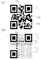
本実施例の光学コード1は、薬剤の包装箱に付される商品管理用の光学コードである。かかる光学コード1は、可視光で読み取る場合に二次元コードの中で最も普及しているQRコード(登録商標)と互換性を有するものであり、その基本構造は、QRコードに準拠したものとなっている。具体的には、図1(a)に示すように、本実施例の光学コード1は、正方形のモジュール2を、縦横に21個ずつマトリクス状に配置してなるものである。モジュール2は、可視光の反射率が高くなるように明色(白色)で配色された明色モジュール2aと、可視光の反射率が低くなるように暗色(黒色)で配色された暗色モジュール2bとからなり、明色モジュール2aと暗色モジュール2bのパターンによってデータを記録している。また、図1(b)に示すように、光学コード1は、QRコードと同様に、機能パターン(固定領域)3と符号化領域4とによって構成される。機能パターン3は、QRコードにあって明色モジュール2aと暗色モジュール2bの位置が予め定められている領域であり、光学コード1の光学的読取りを補助する位置検出パターン5、分離パターン6、タイミングパターン7などによって構成される。符号化領域4は、明色モジュール2aと暗色モジュール2bのパターンによってデータを記録する領域であり、データコード語及び誤り訂正コード語が記録されるデータコード領域8と、形式情報を示すコードが配置される形式情報コード領域9とによって構成される。こうした構成は、基本的に、QRコードのJIS規格(JIS X 0510:2004)に準拠したものであるため詳細な説明は省略する。
The
本実施例の光学コード1の暗色モジュール2bは、1000nmの波長の赤外光(以下、実施例4を除いて、単に「赤外光」という。)の反射率の高い赤外光反射暗色モジュール2baと、赤外光の反射率の低い赤外光吸収暗色モジュール2bbとで構成される。具体的には、図2において、白く表されたモジュールが明色モジュール2aであり、「×」でマークされたモジュールが赤外光反射暗色モジュール2baであり、黒く表されたモジュールが赤外光吸収暗色モジュール2bbである。本実施例では、機能パターン3の左上の位置検出パターン5を構成する暗色モジュール2bに、赤外光反射暗色モジュール2baと赤外光吸収暗色モジュール2bbの特徴的なパターン(以下、正規品識別パターンという。)が設けられている。具体的には、左上の位置検出パターン5を構成する暗色モジュール2bは、中央の正方形を構成する9個の暗色モジュールが、赤外光反射暗色モジュール2baで構成され、外周部を構成する24個の暗色モジュールが、赤外光吸収暗色モジュール2bbで構成される。なお、機能パターン3の残りの暗色モジュール、及び、符号化領域4の全ての暗色モジュールは、全て赤外光吸収暗色モジュール2bbで構成される。赤外光反射暗色モジュール2baと赤外光吸収暗色モジュール2bbは、赤外光の反射特性を測定することで明確に識別可能であるが、可視光レベルでは、いずれも黒色であるため、両モジュールを識別するのは困難である。なお、明色モジュール2aは、可視光と赤外光の反射率の高いモジュールのみによって構成される。すなわち、本実施例の光学コード1の各モジュール2は、可視光の反射率(明度)を測定することで、可視光の反射率の高い明色モジュール2aと、可視光の反射率の低い暗色モジュール2bとを識別できる。そして、赤外光の反射率を測定することで、赤外光の反射率の低い赤外光吸収暗色モジュール2bbと、赤外光の反射率の高いその他のモジュール(明色モジュール2a及び赤外光反射暗色モジュール2ba)とを識別できる。
The
本実施例の光学コード1は、包装箱を構成する白色の紙基材10の表面に、印刷により黒色インキ11a,11bの層を形成することにより作成される。具体的には、図3(a)に示すように、黒色インキ11a,11bの層を印刷せず、紙基材10の表面が露出する部分が、可視光の反射率が高い明色モジュール2aとなり、黒色インキ11a,11bの層が形成された部分が、可視光の反射率が低い暗色モジュール2bとなる。黒色インキ11a,11bは、赤外光を透過する赤外光透過黒色インキ11aと、赤外光を吸収する赤外光吸収黒色インキ11bの二種類が用いられる。紙基材10は、赤外光の反射率が高いものであり、図3(b)に示すように、赤外光透過黒色インキ11aの層(本発明に係る第一の暗色層に相当)が形成された部分は、赤外光がインキ11aを透過して紙基材10で反射するため赤外光反射暗色モジュール2baとなる。一方、赤外光吸収黒色インキ11bの層(本発明に係る第二の暗色層に相当)が形成された部分は、赤外光がインキ11bに吸収されるため赤外光吸収暗色モジュール2bbとなる。なお、一般的に、白色の紙基材は赤外光の反射率が高く、また、黒色染料インキは一般的に赤外光を透過し、黒色顔料インキは一般的に赤外光を吸収するため、本実施例の光学コード1は、一般的な材料で作成可能である。
The
本実施例の光学コード1は、例えば、以下のステップからなる作成方法によって容易に作成できる。
(1)記録データの準備
明色モジュール2aと暗色モジュール2bのパターンによって符号化領域4に記録するデータを用意する。
(2)QRコード準拠データの作成
ステップ(1)で準備したデータを記録するQRコードの情報を作成する。すなわち、かかるステップにおいて、光学コード1の明色モジュール2aと暗色モジュール2bのパターンを決定する。かかるステップは、公知のQRコードの作成方法に則って実現できるため、詳細な説明は省略する。
(3)赤外光反射暗色モジュールと赤外光吸収暗色モジュールの決定
ステップ(2)で決定した各暗色モジュール2bについて、赤外光反射暗色モジュール2baと、赤外光吸収暗色モジュール2bbのいずれであるかを決定する。具体的には、機能パターン3の左上の位置検出パターン5の中央部を構成する9つの暗色モジュール2bを、赤外光反射暗色モジュール2baと決定し、残り全ての暗色モジュール2bを赤外光吸収暗色モジュール2bbと決定する。かかるステップにより、光学コード1の全てのモジュール2の種類が決定される。
(4)印刷
包装箱を構成する白色の紙基材10に、黒色インキ11a,11bで光学コード1を印刷する。具体的には、紙基材10の表側に赤外光透過黒色インキ11aの層を形成することにより黒色の赤外光反射暗色モジュール2baを印刷し、紙基材10の表側に赤外光吸収黒色インキ11bの層を形成することにより黒色の赤外光吸収暗色モジュール2bbを印刷する。明色モジュール2aの部分は、インキ11a,11bを印刷せず、紙基材10の表面の白色で形成する。かかる印刷ステップは、版を用いて印刷してもよいし、プリンタ(インクジェットプリンタやレーザープリンタ)を用いて印刷してもよい。
The
(1) Preparation of recorded data Data to be recorded in the
(2) Creation of QR code compliant data Create QR code information to record the data prepared in step (1). That is, in such a step, the patterns of the
(3) Determination of infrared light reflection dark color module and infrared light absorption dark color module For each
(4) Printing The
本実施例の光学コード1は、一般的なQRコードの読取装置(スマートフォン等)で読み取ると、明色モジュール2aは明色のモジュールと識別され、暗色モジュール2bは暗色のモジュールと識別される。一般的なQRコードの読取装置は、可視光の反射特性(明度)のみよって、各モジュール2の明暗を識別するためである。そして、明色モジュール2aと暗色モジュール2bのパターンは、QRコードの規格に準拠しているため、明色モジュール2aと暗色モジュール2bのパターンによって光学コード1に記録された情報は、一般的なQRコードの読取装置で読み取られることとなる。このように、本実施例の光学コード1は、可視光で読み取る場合には、QRコードと互換性を有するものとなる。
When the
本実施例の光学コード1をコピー機で複写する場合、コピー機に内蔵されたスキャナは、赤外光反射特性を測定しないため、赤外光反射暗色モジュール2baと赤外光吸収暗色モジュール2bbは、同じ「黒色(暗色)」として識別される。したがって、コピー機によって複写された複写物では、全ての暗色モジュール2bが、同じインキで黒色に印刷されることとなる。一般的なコピー機には、黒色を赤外光透過インキ(多くは染料インキ)で印刷するものと、赤外光吸収インキ(多くは顔料インキ)で印刷するものがあるが、いずれのコピー機で複写した場合であっても、複写した光学コードでは、複写元の光学コード1に設けられた赤外光反射暗色モジュール2baと赤外光吸収暗色モジュール2bbのパターンが失われる。このように、本実施例の光学コード1は、赤外光を照射した場合は、可視光を照射した場合とは異なるモジュールのパターンが読み取られるものであり、赤外光で読み取られるパターンは、複写機では複写困難であるため、赤外光の反射特性を測定して、正規品識別コードが設けられているか否かを判定することで、オリジナルの光学コード1と複写物を判別できる。
When the
本実施例の光学コード1の具体的な使用方法を説明する。
本実施例の光学コード1は、薬剤の包装箱に印刷される。かかる光学コード1は、明色モジュール2aと暗色モジュール2bのパターンによって、商品管理に使用する商品情報を含んでいる。商品情報は、製造者ID、商品識別コード、有効期限日、ロット番号、シリアル番号を含んでいる。なお、かかる商品情報は、GS1識別コードの規格に則ったものである。また、商品情報に含まれる情報は、これらに限定されず、適宜変更可能である。
A specific method of using the
The
一般的に、薬剤は「製造者」→「卸売業者」→「医療機関」or「薬局」→「消費者」の順番に流通する。本実施例の光学コード1を包装箱に印刷した薬剤は、製造者の出荷時、卸売業者の入荷時及び出荷時、医療機関や薬局での入荷時、消費者への販売時などに、光学コード1に記録された商品情報を読み取ることで、商品管理を行うことができる。商品情報は、明色モジュール2aと暗色モジュール2bのパターンで記録されているため、一般的なQRコードの読取装置を使用して読み取ることが可能である。すなわち、本実施例の光学コード1は、基本的な商品管理は、低廉な読取装置を使用して実現できる。
Generally, drugs are distributed in the order of "manufacturer"-> "wholesale"-> "medical institution" or "pharmacy"-> "consumer". The drug in which the
一方で、薬剤は、非正規品(偽造品)の流通が深刻な問題となっているため、商品の流通過程において非正規品の混入防止が求められる。本実施例の光学コード1が包装箱に印刷された薬剤は、正規品識別パターンの有無に基づいて当該包装箱の光学コード1が複写物であるか否かを判定することで、商品の正規品確認を行うことができる。
On the other hand, since the distribution of non-genuine products (counterfeit products) has become a serious problem for chemicals, it is required to prevent non-genuine products from being mixed in the product distribution process. The drug in which the
本実施例の光学コード1は、商品管理に使用する商品情報を記録するものであるから、商品情報の読取作業と同時に、正規品識別パターンの有無によって光学コード1の真贋判定を行うことで、商品の正規品確認作業を、商品確認作業と同時に行うことが可能となる。例えば、以下に説明する専用読取装置を使用することで、本実施例の光学コード1に対して、商品情報の読取作業と商品の正規品確認作業を、一度の作業で実行可能となる。
Since the
以下に、商品情報の読取作業と正規品確認作業を同時に実行可能な専用読取装置について説明する。専用読取装置は、可視光及び赤外光を検知可能な撮像素子を備えた撮像部と、可視光を遮断して赤外光を透過させる赤外光フィルタと、赤外光を遮断して可視光を透過する可視光フィルタと、赤外光フィルタと可視光フィルタを光路に対して挿脱可能とする挿脱機構と、赤外光と可視光を照射可能な照射部と、画像の撮像及びデータ処理を制御する制御部と、各種情報を表示する表示部と、データを外部出力する通信部とを備えている。撮像部は、照射部が光学コードに照射した光が反射してなす反射光により光学コードの画像を撮像可能なものであり、可視光が反射してなす反射光の撮像画像から得られるモジュールのパターンに基づいて、情報を読み取り可能な可視光記録データ読取部と、赤外光が反射してなす反射光の撮像画像から得られるモジュールのパターンに基づいて、情報を読み取り可能な不可視光記録データ読取部とを備えている。また、制御部は、可視光記録データ読取部が読み取った情報と、不可視光記録データ読取部が読み取った情報に基づいて、真贋を判定する真贋判定処理部を備えている。 The dedicated reading device capable of simultaneously performing the product information reading work and the genuine product confirmation work will be described below. The dedicated reading device includes an imaging unit equipped with an imaging element capable of detecting visible light and infrared light, an infrared light filter that blocks visible light and transmits infrared light, and an infrared light filter that blocks visible light and is visible. A visible light filter that transmits light, an insertion / removal mechanism that allows the infrared light filter and visible light filter to be inserted and removed from the optical path, an irradiation unit that can irradiate infrared light and visible light, image imaging, and image capture. It includes a control unit that controls data processing, a display unit that displays various types of information, and a communication unit that outputs data externally. The image pickup unit is capable of capturing an image of the optical code by the reflected light formed by reflecting the light emitted by the irradiation unit on the optical code, and is a module obtained from the captured image of the reflected light formed by the reflection of visible light. Invisible light recording data that can read information based on the pattern of the visible light recording data reader that can read information based on the pattern and the module obtained from the captured image of the reflected light that is reflected by infrared light. It is equipped with a reading unit. Further, the control unit includes an authenticity determination processing unit that determines authenticity based on the information read by the visible light recording data reading unit and the information read by the invisible light recording data reading unit.
専用読取装置は、以下の手順によって、商品情報の読取作業と正規品確認作業を同時に実行する。
(1)可視光撮像処理
光学コード1の可視光の画像を撮像する。具体的には、赤外光フィルタを光路から外し、可視光フィルタを光路に挿入した状態で光学コード1を撮像する。また、必要に応じて、照射部によって光学コード1を可視光で照らす。
(2)赤外光撮像処理
光学コード1の赤外光の画像を撮像する。具体的には、可視光フィルタを光路から外し、赤外光フィルタを光路に挿入した状態で光学コード1を撮像する。また、必要に応じて、照射部によって光学コード1を赤外光で照らす。
(3)可視光反射特性識別処理
可視光撮像処理で撮像した画像に基づいて、光学コード1を構成する各モジュール2の位置を特定し、各モジュール2が、明色モジュール2aと暗色モジュール2bのいずれであるか識別する。かかるステップは、公知のQRコードの読取方法によって実現可能である。
(4)商品情報読取処理
符号化領域4の明色モジュール2aと暗色モジュール2bのパターンに記録された商品情報を読み取る。かかるステップは、公知のQRコードの読取方法によって実現可能である。
(5)赤外光反射特性識別処理
赤外光撮像処理で撮像した画像に基づいて、光学コード1を構成する各モジュール2の位置を特定し、各モジュール2が、赤外光の反射率の高いモジュール(明色モジュール2a及び赤外光反射暗色モジュール2ba)と、赤外光の反射率の低いモジュール(赤外光吸収暗色モジュール2bb)のいずれであるかを識別する。そして、可視光反射特性識別処理の結果と組み合わせることにより、光学コード1の各モジュール2が、明色モジュール2aと、赤外光反射暗色モジュール2baと、赤外光吸収暗色モジュール2bbのいずれであるかを識別する。ここで、赤外光で撮像した画像から各モジュール2の位置の特定を複数回試みて、特定不能であった場合には、そのまま、次の真贋判定処理に進む。なお、赤外光反射特性識別処理では、赤外光で撮像した画像に含まれる機能パターン3に基づいて、画像内の各モジュール2の位置を特定する。赤外光で撮像した画像には、左上の位置検出パターン5は不完全であるものの、各モジュール2の位置を十分に特定可能な機能パターン3が含まれているためである。
(6)真贋判定処理
赤外光反射特性識別処理の結果に基づいて、左上の位置検出パターン5に、正規品識別パターンが存在するか否かを判定する。ここで、正規品識別パターンが存在すると判定した場合は、当該光学コードが包装箱に付された商品を正規品であると判定する。一方、正規品識別パターンが存在しないと判定した場合は、当該光学コードが包装箱に付された商品を非正規品であると判定する。また、商品情報読取処理において、商品情報の読取りに成功したが、赤外光反射特性識別処理で、モジュール2の位置を特定不能であった場合も、当該光学コードが包装箱に付された商品を非正規品であると判定する。
(7)結果出力処理
商品情報読取処理で読み取った商品情報と真贋判定処理の判定結果を、表示部に表示するとともに、通信部を介して外部出力する。
The dedicated reader simultaneously executes the product information reading operation and the genuine product confirmation operation according to the following procedure.
(1) Visible light imaging process An image of visible light of the
(2) Infrared light imaging process An infrared light image of the
(3) Visible light reflection characteristic identification process Based on the image captured by the visible light imaging process, the position of each
(4) Product information reading process The product information recorded in the patterns of the
(5) Infrared light reflection characteristic identification process Based on the image captured by the infrared light imaging process, the position of each
(6) Authenticity determination processing Based on the result of the infrared light reflection characteristic identification processing, it is determined whether or not a genuine product identification pattern exists in the upper left
(7) Result output process The product information read by the product information reading process and the determination result of the authenticity determination process are displayed on the display unit and output externally via the communication unit.
以上のように、薬剤の包装箱に付された本実施例の光学コード1は、一般的なQRコードの読取装置によって商品情報を読取可能であるため、流通過程の各段階で、光学コード1に記録された商品情報を低コストで読み取って商品管理を行うことができる。また、本実施例の光学コード1は、各モジュール2の赤外光の反射率を測定して、正規品識別パターンが所定位置に存在するか否かを判定することで、複写物を検出できるため、当該光学コード1の複写物を包装箱に使用した非正規品の流通を適切に防止可能となる。
As described above, since the
ここで、商品情報の読取りは流通過程の各段階で、略全ての商品について必要となるが、正規品確認作業は、流通過程の全ての段階で実施する必要はなく、また、抜き打ち検査や、抜取り検査によって一部の商品について実施するだけでも一定の効果が得られるため、正規品確認作業は、商品情報の読取りに比べて少ない頻度で実施すれば足りる。このように、本実施例の光学コード1は、複写物の判別に赤外光の反射率を測定可能な専用装置が必要となるが、実施頻度は少なくて済むため、低コストで実現できる。
Here, reading of product information is required for almost all products at each stage of the distribution process, but genuine product confirmation work does not have to be carried out at all stages of the distribution process, and unannounced inspections and unannounced inspections are required. Since a certain effect can be obtained by performing the sampling inspection only for some products, it is sufficient to carry out the genuine product confirmation work less frequently than reading the product information. As described above, the
特に、本実施例の光学コード1は、商品管理に用いる商品情報を記録しているため、薬剤の流通過程において商品管理を行う際に、光学コード1に記録された商品情報の読取りと同時に、該光学コード1に記録された正規品識別パターンを確認することで、商品の正規品確認作業を簡易に実行できるという利点がある。
In particular, since the
また、本実施例の光学コード1は、赤外光反射暗色モジュール2baと赤外光吸収暗色モジュール2bbによって、左上の位置検出パターン5に正規品識別パターンを形成されているか否かを判定するだけで、オリジナルの光学コード1と複写物とを判別できるため、光学コード1の複写物を容易に検出できるという利点がある。
Further, the
なお、本実施例では、上述の赤外光反射特性識別処理で、赤外光で撮像した画像に含まれる不完全な機能パターン3に基づいて、画像内の各モジュール2の位置を特定しているが、可視光撮像処理で撮像した画像では、完全な機能パターンに基づいて、各モジュール2の位置を特定可能であるため、赤外光撮像処理で撮像した画像を、可視光撮像処理で撮像した画像と重ね合わせることにより、赤外光撮像処理で撮像した画像に含まれる各モジュール2の位置を特定してもよい。
In this embodiment, in the above-mentioned infrared light reflection characteristic identification process, the position of each
本実施例は、上記実施例1の構成を一部変更したものである。このため、実施例1と共通する構成については、図中で同一符号を付して、説明を省略する。 This embodiment is a partial modification of the configuration of the first embodiment. Therefore, the same components as those in the first embodiment are designated by the same reference numerals in the drawings, and the description thereof will be omitted.
本実施例の光学コード1aは、実施例1と同様に、暗色モジュール2bが、赤外光反射暗色モジュール2baと、赤外光吸収暗色モジュール2bbとで構成される。図4において、白色で塗りつぶされたモジュールは、明色モジュール2aであり、「×」でマークされたモジュールは赤外光反射暗色モジュール2baであり、黒色で塗りつぶされたモジュールは赤外光吸収暗色モジュール2bbである。本実施例では、機能パターン3を構成する暗色モジュール2bは、全て赤外光吸収暗色モジュール2bbで構成される。そして、符号化領域4に含まれる暗色モジュール2bは、赤外光反射暗色モジュール2baと赤外光吸収暗色モジュール2bbで構成される。
In the
本実施例の光学コード1aは、データを記録する領域が二種類設けられている。一つは、実施例1と同様にして、符号化領域4における明色モジュール2aと暗色モジュール2bのパターンによってデータを記録する可視光記録領域である。もう一つは、符号化領域4における赤外光反射暗色モジュール2baと赤外光吸収暗色モジュール2bbのパターンによってデータを記録する赤外光記録領域である。
The
可視光記録領域には、実施例1と同様に、商品情報(製造者ID、商品識別コード、有効期限日、ロット番号、シリアル番号)が記録される。可視光記録領域に記録された商品情報は、実施例1と同様に、QRコードの規格にしたがって記録されており、一般的なQRコードの読取装置で読取可能となっている。このように、可視光記録領域は、一般的なQRコードの読取装置によって情報を読取可能であり、容易に記録情報を読取可能な公開領域としての性格を有している。 Product information (manufacturer ID, product identification code, expiration date, lot number, serial number) is recorded in the visible light recording area as in the first embodiment. The product information recorded in the visible light recording area is recorded according to the QR code standard as in the first embodiment, and can be read by a general QR code reader. As described above, the visible light recording area has a character as a public area in which information can be read by a general QR code reading device and the recorded information can be easily read.
赤外光記録領域には、正規品であることを示す正規品識別コードが記録される。具体的には、ASCIIコードで符号化した正規品識別コードを暗号化し、さらに、誤り訂正符号を付与してなるバイナリデータが、符号化領域4における赤外光反射暗色モジュール2baと赤外光吸収暗色モジュール2bbのパターンによって記録される。このため、赤外光記録領域に記録された正規品識別コードは、赤外光の反射率を測定可能であって、かつ、暗号化された正規品識別コードを復号するための復号キーを記録した専用の読取装置でなければ読み取ることができない。このように、赤外光記録領域は、特殊な読取装置を具備したものだけが、記録情報を読取可能な秘匿領域としての性格を有している。
In the infrared light recording region, a genuine product identification code indicating that the product is genuine is recorded. Specifically, the binary data obtained by encrypting the genuine product identification code encoded by the ASCII code and further adding the error correction code is the infrared light reflection dark color module 2ba and the infrared light absorption in the
このように、本実施例の光学コード1aは、赤外光反射暗色モジュール2baと赤外光吸収暗色モジュール2bbのパターンによってデータを記録することで、明色モジュール2aと暗色モジュール2bのパターンによって記録するデータとは別に、一般のQRコードの読取装置では読取困難な秘匿性の高いデータを記録できるという利点がある。
As described above, the
本実施例の光学コード1aには、実施例1と同様に、明色モジュール2aと暗色モジュール2bのパターンによって商品情報が記録されるため、光学コード1aが包装箱に付された薬剤は、流通過程における各段階で、一般的なQRコードの読取装置を使用して商品情報を読み取って、商品管理を行うことができる。
Since the product information is recorded in the
一方、赤外光記録領域に記録された正規品識別コードについては、上述のように、専用の読取装置を使用すれば読み取ることができる。ここで、本実施例の光学コード1aをコピー機で複写した場合、実施例1と同様に、複写物では、赤外光反射暗色モジュール2baと赤外光吸収暗色モジュール2bbのパターンが失われるため、赤外光記録領域に記録されたデータは失われる。このため、本実施例の光学コード1aは、専用の読取装置を用いて、赤外光反射暗色モジュール2baと赤外光吸収暗色モジュール2bbのパターンによって正規品識別コードが記録されているか否かを判定することで、包装箱に付された光学コードが、正規の光学コード1aであるか否かを判定できる。したがって、本実施例の光学コード1aも商品の正規品確認に用いることができる。
On the other hand, the genuine identification code recorded in the infrared light recording region can be read by using a dedicated reading device as described above. Here, when the
本実施例の光学コード1aは、例えば、以下のステップからなる作成方法によって、容易に作成できる。
(1)記録データの準備
可視光記録領域に記録するデータ(商品情報)を用意する。
(2)QRコード準拠データの作成
ステップ(1)で準備した商品情報を記録するQRコードの情報を作成する。すなわち、光学コード1aにおける明色モジュール2aと暗色モジュール2bのパターンを決定する。かかるステップは、公知のQRコードの作成方法に則って実現できるため、詳細な説明は省略する。
(3)赤外光記録領域の記録データの作成
赤外光記録領域に記録するデータ(正規品識別コード)を用意する。具体的には、正規品識別コードを符号化、暗号化し、誤り訂正符号を付加する。
(4)赤外光反射暗色モジュールと赤外光吸収暗色モジュールの決定
ステップ(2)で決定した各暗色モジュール2bについて、赤外光反射暗色モジュール2baと、赤外光吸収暗色モジュール2bbのいずれであるかを決定する。具体的には、ステップ(3)で用意したデータ(正規品識別コード)のバイナリデータの1ビットを、符号化領域4の1つの暗色モジュール2bに記録させるようにして、記録させるビットが「1」である場合は、当該暗色モジュール2bを赤外光反射暗色モジュール2baと決定し、記録させるビットが「0」である場合は、当該暗色モジュール2bを赤外光吸収暗色モジュール2bbと決定する。かかるステップにより、全てのモジュール2のパターンが決定される。なお、記録させるバイナリデータの各ビットを、符号化領域4のどの暗色モジュール2bに記録させるかは、適宜決定可能である。例えば、符号化領域4の暗色モジュール2bを、一番上の行の左端のものから順位付けして、最上位の暗色モジュール2bから順番に、前記バイナリデータを1ビットずつ記録させることが挙げられる。また、インターリーブを行い、一定数の暗色モジュール2b毎にバイナリーデータを記録させるようにしてもよい。
(5)印刷
実施例1と同様にして、包装箱を構成する紙基材10に、黒色インキ11a,11bで光学コード1aを印刷する。
The
(1) Preparation of recorded data Prepare data (product information) to be recorded in the visible light recording area.
(2) Creation of QR code compliant data Create QR code information that records the product information prepared in step (1). That is, the patterns of the
(3) Creation of recording data in the infrared light recording area Prepare data (genuine product identification code) to be recorded in the infrared light recording area. Specifically, the genuine product identification code is encoded and encrypted, and an error correction code is added.
(4) Determination of infrared light reflection dark color module and infrared light absorption dark color module For each
(5) Printing In the same manner as in Example 1, the
本実施例の光学コード1aは、実施例1と同様に、商品情報の読取作業と同時に正規品識別コードの有無により正規品確認を行うことで、正規品確認作業の手間を削減できる。以下に、商品情報の読取作業と正規品確認作業を同時に実行可能な専用読取装置について説明する。
専用読取装置のハードウェア構成は、実施例1で説明した専用読取装置と同じである。専用読取装置は、以下の手順によって、商品情報の読取作業と正規品確認作業を同時に実行する。なお、下記の(1)〜(5)の処理については、実施例1で説明した処理と同様であるため、共通の処理名称のみを記して説明を省略する。
(1)可視光撮像処理
(2)赤外光撮像処理
(3)可視光反射特性識別処理
(4)商品情報読取処理
(5)赤外光反射特性識別処理
(6)赤外光記録領域読取処理
符号化領域4の赤外光反射暗色モジュール2baと赤外光吸収暗色モジュール2bbのパターンに記録されたデータを読み取る。具体的には、誤り訂正符号を用いて誤りの検出・訂正を行い、暗号化されたデータを復号する。
(7)真贋判定処理
赤外光記録領域に記録されたデータを、専用読取装置に予め記録された正規品識別コードと照合して、データが正規品識別コードと一致した場合には、当該光学コードが包装箱に付された商品を正規品であると判定する。一方、赤外光記録領域に記録されたデータが正規品識別コードと一致しない場合や、赤外光記録領域に記録されたデータが読取不能であった場合、また、商品情報読取処理において、商品情報の読取りに成功したが、赤外光反射特性識別処理で、光学コード1を構成するモジュール2の切出しに失敗した場合は、当該光学コードが包装箱に付された商品を非正規品であると判定する。
(8)結果出力処理
商品情報読取処理で読み取った商品情報と真贋判定処理の判定結果を、表示部に表示するとともに、通信部を介して外部出力する。
Similar to the first embodiment, the
The hardware configuration of the dedicated reader is the same as that of the dedicated reader described in the first embodiment. The dedicated reader simultaneously executes the product information reading operation and the genuine product confirmation operation according to the following procedure. Since the processes (1) to (5) below are the same as the processes described in the first embodiment, only the common process names will be described and the description will be omitted.
(1) Visible light imaging process (2) Infrared light imaging process (3) Visible light reflection characteristic identification process (4) Product information reading process (5) Infrared light reflection characteristic identification process (6) Infrared light recording area reading Processing Reads the data recorded in the patterns of the infrared light reflection dark color module 2ba and the infrared light absorption dark color module 2bb in the
(7) Authenticity determination processing The data recorded in the infrared light recording area is collated with the genuine product identification code recorded in advance in the dedicated reader, and if the data matches the genuine product identification code, the optical The product with the code attached to the packaging box is judged to be genuine. On the other hand, if the data recorded in the infrared light recording area does not match the genuine product identification code, or if the data recorded in the infrared light recording area is unreadable, or in the product information reading process, the product If the information is successfully read, but the
(8) Result output process The product information read by the product information reading process and the determination result of the authenticity determination process are displayed on the display unit and output externally via the communication unit.
以上のように、本実施例の光学コード1aは、実施例1の光学コード1と同様に、可視光で撮像する一般的な読取装置で商品情報を読み取ることができるため、商品管理に要するコストを抑えつつ、光学コードの複写による悪用を防止できる。
As described above, the
また、本実施例の光学コード1aでは、赤外光記録領域に正規品識別コードが記録されているか否かによって、光学コード1aの真贋を判定するため、光学コード1aの複写品だけでなく、商品情報の内容を改ざんした偽造光学コードも検出できる。商品情報の内容を改ざんするためには、明色モジュール2aと暗色モジュール2bの位置を改変しなければならないが、明色モジュール2aと暗色モジュール2bの位置を改変した偽造光学コードでは、暗色モジュール2bに記録された正規品識別コードが失われてしまうためである。したがって、本実施例の構成によれば、光学コード1aのデータを改ざんした偽造光学コードの流通も適切に取り締まることが可能となる。
Further, in the
また、本実施例の光学コード1aは、機能パターン3の暗色モジュール2bが全て赤外光吸収暗色モジュール2bbであるため、赤外光で撮像した画像には、明色モジュール2aと暗色モジュール2bが形成する機能パターン3が、そのまま写ることとなる。したがって、本実施例によれば、赤外光で撮像した画像において、当該画像に含まれる機能パターン3に基づいて各モジュール2の位置を容易に特定できるという利点がある。
Further, in the
なお、本実施例では、真贋判定処理において、赤外光記録領域に正規品識別コードが記録されている場合に、当該光学コード1を正規のものであると判定しているが、かかる判定に替えて、符号化領域4の暗色モジュール2bが、赤外光反射暗色モジュール2baと赤外光吸収暗色モジュール2bbの二種類で構成されている場合は、当該光学コードを正規のものであると判定するようにしてもよい。
In this embodiment, in the authenticity determination process, when the genuine product identification code is recorded in the infrared light recording region, it is determined that the
また、本実施例では、赤外光記録領域に真贋判定処理に用いる正規品識別コードのみを記録しているが、赤外光記録領域に、その他の情報を記録するよう構成してもよい。 Further, in this embodiment, only the genuine identification code used for the authenticity determination process is recorded in the infrared light recording area, but other information may be recorded in the infrared light recording area.
本実施例は、上記実施例2の構成を一部変更したものである。このため、実施例2と共通する構成については説明を省略する。 This embodiment is a partial modification of the configuration of the second embodiment. Therefore, the description of the configuration common to the second embodiment will be omitted.
本実施例の光学コードは、赤外光記録領域に正規品識別コードでなく、商品のシリアルコードを記録したことを特徴とする。商品のシリアルコードは、可視光記録領域の商品情報にも含まれるため、本実施例の光学コードでは、可視光記録領域と赤外光記録領域に商品のシリアルコードが重複して記録される。 The optical code of this embodiment is characterized in that the serial code of the product is recorded in the infrared light recording region instead of the genuine product identification code. Since the serial code of the product is also included in the product information in the visible light recording area, in the optical code of this embodiment, the serial code of the product is duplicated in the visible light recording area and the infrared light recording area.
本実施例の光学コードは、可視光記録領域と赤外光記録領域に記録されたシリアルコードを照合して、一致していた場合に正規の光学コードであると判定することができる。実施例2と同様に、本実施例の光学コードをコピー機で複写した複写物では、赤外光反射暗色モジュール2baと赤外光吸収暗色モジュール2bbのパターンが失われて、赤外光記録領域に記録されたデータが失われるためである。 The optical code of this embodiment can be determined to be a regular optical code by collating the serial code recorded in the visible light recording area and the infrared light recording area and if they match. Similar to Example 2, in the copy obtained by copying the optical code of this example with a copier, the patterns of the infrared light reflection dark color module 2ba and the infrared light absorption dark color module 2bb are lost, and the infrared light recording area is lost. This is because the data recorded in is lost.
本実施例と実施例2を比較すると、本実施例の光学コードは、可視光記録領域のデータと、赤外光記録領域のデータとを照合することにより、光学コードの真贋を判定するため、真贋判定を実行する装置に、照合用のデータ(実施例2に係る正規品識別コード)を記録しなくてもよいという利点がある。また、赤外光記録領域に記録されるデータが、可視光記録領域に記録される商品情報と密接に関連付けられているため、商品情報を改ざんした偽造光学コードの作成が一層困難となる。 Comparing the present embodiment and the second embodiment, the optical code of the present embodiment is used to determine the authenticity of the optical code by collating the data in the visible light recording region with the data in the infrared light recording region. There is an advantage that it is not necessary to record the verification data (genuine product identification code according to the second embodiment) in the device that executes the authenticity determination. Further, since the data recorded in the infrared light recording area is closely related to the product information recorded in the visible light recording area, it becomes more difficult to create a counterfeit optical code in which the product information is falsified.
本実施例は、上記実施例2の構成を一部変更したものである。このため、実施例2と共通する構成については、図中で同一符号を付して、説明を省略する。 This embodiment is a partial modification of the configuration of the second embodiment. Therefore, the same components as those in the second embodiment are designated by the same reference numerals in the drawings, and the description thereof will be omitted.
本実施例の光学コード1bは、実施例2(図4参照)と同様に、符号化領域4を構成する暗色モジュール2bが、赤外光反射暗色モジュール2baと、赤外光吸収暗色モジュール2bbとで構成される。ここで、図5に示すように、本実施例では、赤外光反射暗色モジュール2baが、第一赤外光反射暗色モジュール2baaと、第二赤外光反射暗色モジュール2babとで構成される。第一赤外光反射暗色モジュール2baaは、可視光、及び880nmの赤外光の反射率が低く、1000nmの赤外光の反射率が高いものである。第二赤外光反射暗色モジュール2babは、可視光、及び880nmの赤外光の反射率が低く、1000nmの赤外光の反射率が高いものである。図6において、白く表示されたもモジュールは、明色モジュール2aであり、「×」でマークされたモジュールが第一赤外光反射暗色モジュール2baaであり、「○」でマークされたモジュールが第二赤外光反射暗色モジュール2babであり、黒く表示されたモジュールが赤外光吸収暗色モジュール2bbである。
In the
本実施例の光学コード1bは、データを記録する領域が二種類設けられている。一つは、符号化領域4における明色モジュール2aと暗色モジュール2bのパターンによってデータを記録する可視光記録領域である。もう一つは、符号化領域4における第一赤外光反射暗色モジュール2baaと、第二赤外光反射暗色モジュール2babと、赤外光吸収暗色モジュール2bbのパターンによってデータを記録する赤外光記録領域である。
The
可視光記録領域には、実施例2と同様に、商品情報(製造者ID、商品識別コード、有効期限日、ロット番号、シリアル番号)が記録される。可視光記録領域に記録された商品情報は、実施例2と同様に、QRコードの規格にしたがって記録されており、一般的なQRコードの読取装置で読取可能となっている。 Product information (manufacturer ID, product identification code, expiration date, lot number, serial number) is recorded in the visible light recording area as in the second embodiment. The product information recorded in the visible light recording area is recorded according to the QR code standard as in the second embodiment, and can be read by a general QR code reader.
赤外光記録領域には、実施例2と同じ正規品識別コードが記録される。ここで、本実施例では、ASCIIコードで符号化した正規品識別コードを暗号化し、さらに、誤り訂正符号を付与してなるバイナリデータを作成し、3進数に変換する。そして、当該3進数のデータを、符号化領域4における第一赤外光反射暗色モジュール2baaと、第二赤外光反射暗色モジュール2babと、赤外光吸収暗色モジュール2bbのパターンによって記録する。このため、本実施例の赤外光記録領域に記録された正規品識別コードは、880nmと1000nmの赤外光の反射率を個別に測定可能であって、かつ、暗号化された正規品識別コードを復号するための復号キーを記録した専用の読取装置でなければ読み取ることができない。このように、赤外光記録領域は、特殊な読取装置を具備したものだけが、記録情報を読取可能な秘匿領域としての性格を有している。
The same genuine identification code as in Example 2 is recorded in the infrared light recording region. Here, in this embodiment, the genuine product identification code encoded by the ASCII code is encrypted, and binary data to which an error correction code is added is created and converted into a ternary number. Then, the ternary data is recorded by the pattern of the first infrared light reflection dark color module 2baa, the second infrared light reflection dark color module 2bab, and the infrared light absorption dark color module 2bb in the
本実施例の光学コード1bは、包装箱を構成する白色の紙基材10の表面に、印刷により3種類の黒色インキの層を形成することにより作成される。具体的には、黒色インキを印刷せず、紙基材10の表面が露出する部分が、可視光の反射率が高い明色モジュール2aとなり、黒色インキの層が形成された部分が、可視光の反射率が低い暗色モジュール2bとなる。黒色インキは、880nm赤外光を吸収し、1000nmの赤外光を透過する第一の赤外光透過黒色インキと、880nmの赤外光及び1000nmの赤外光を透過する第二の赤外光透過黒色インキと、880nmの赤外光、及び1000nmの赤外光を吸収する赤外光吸収黒色インキの二種類が用いられる。すなわち、第一の赤外光透過黒色インキの層が形成された部分は、1000nmの赤外光のみがインキを透過して紙基材で反射するため第一赤外光反射暗色モジュール2baaとなる。また、第二の赤外光透過黒色インキの層が形成された部分は、880nmの赤外光、及び1000nmの赤外光がインキを透過して紙基材で反射するため第二赤外光反射暗色モジュール2babとなる。そして、赤外光吸収黒色インキの層が形成された部分は、880nmの赤外光、及び1000nmの赤外光がインキに吸収されるため赤外光吸収暗色モジュール2bbとなる。
The
このように、本実施例の光学コード1bは、赤外光の透過特性の相違する三種類のインキを使用して作成されるものであるため、実施例2の光学コードよりも、同構成の光学コード1bの偽造が一層困難である。したがって、本実施例の光学コード1bを包装箱に付した薬剤は、非正規品の流通を防止することができる。
As described above, since the
本実施例は、上記実施例2の構成を一部変更したものである。このため、実施例2と共通する構成については、本文中及び図中と同一符号を付して、説明を省略する。 This embodiment is a partial modification of the configuration of the second embodiment. Therefore, the same reference numerals as those in the text and the drawings will be given to the configurations common to those in the second embodiment, and the description thereof will be omitted.
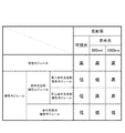
本実施例では、赤外光反射暗色モジュール2baにおける、赤外光の反射率を実施例2よりも低下させたことを特徴とする。具体的には、本実施例では、赤外光反射暗色モジュール2baは、赤外光透過黒色インキ11a単独で形成されるのでなく、赤外光透過黒色インキ11aに、少量の赤外光吸収黒色インキ11bを混合してなる、赤外光半透過黒色インキ11cで形成される。赤外光半透過黒色インキ11cの層では、赤外光は完全には透過せず、一部が吸収されて部分的に透過することとなるため、本実施例では、図7に示すように、赤外光反射暗色モジュール2baにおける赤外光の反射率は50%程度となっている。なお、赤外光反射暗色モジュール2baは、可視光レベルでは黒色となり、可視光の反射特性は赤外光吸収暗色モジュール2bbと同等である。
The present embodiment is characterized in that the reflectance of infrared light in the infrared light reflection dark color module 2ba is lower than that of the second embodiment. Specifically, in this embodiment, the infrared light reflecting dark color module 2ba is not formed by the infrared light transmitting
本実施例の光学コードでは、赤外光の反射率が、明色モジュール2aにおいて高く(75%以上)、赤外光反射暗色モジュール2baにおいて50%程度であり、赤外光吸収暗色モジュール2bbにおいて低く(25%以下)となる。このように、本実施例では、明色モジュール2aと、赤外光反射暗色モジュール2baと、赤外光吸収暗色モジュール2bbの赤外光反射率が夫々相違しているため、専用の読取装置で赤外光の反射率を測定すれば、明色モジュール2aと、赤外光反射暗色モジュール2baと、赤外光吸収暗色モジュール2bbとを識別できる。
In the optical code of this embodiment, the reflectance of infrared light is high in the
本実施例の光学コードには、実施例2と同様に、符号化領域4における赤外光反射暗色モジュール2baと赤外光吸収暗色モジュール2bbのパターンによってデータを記録する赤外光記録領域が設けられ、該赤外光記録領域に正規品識別コードが記録される。本実施例の光学コードをコピー機で複写した場合、実施例2と同様に、複写物では、赤外光反射暗色モジュール2baと赤外光吸収暗色モジュール2bbのパターンが失われるため、赤外光記録領域に記録されたデータは失われる。このため、本実施例の光学コード1は、専用の読取装置を用いて、赤外光反射暗色モジュール2baと赤外光吸収暗色モジュール2bbのパターンによって正規品識別コードが記録されているか否かを判定することで、包装箱に付された光学コードが、正規の光学コードであるか否かを判定できる。したがって、本実施例の光学コードも商品の正規品確認に用いることができる。
Similar to the second embodiment, the optical code of this embodiment is provided with an infrared light recording region for recording data according to the patterns of the infrared light reflection dark color module 2ba and the infrared light absorption dark color module 2bb in the
本実施例の光学コードは、赤外光反射暗色モジュール2baの印刷を赤外光透過黒色インキ11aに替えて赤外光半透過黒色インキ11cを使用する以外は、実施例2の光学コード1aと同様の作成方法によって作成できる。なお、本実施例に係る赤外光反射暗色モジュール2baは、赤外光半透過黒色インキ11cによる印刷に替えて、赤外光透過黒色インキ11aと、少量の赤外光吸収黒色インキ11bの重ね印刷によって形成してもかまわない。
The optical code of the present embodiment is the same as that of the
本実施例の光学コードは、実施例2よりも簡便な方法により、商品情報の読取作業と同時に正規品識別パターンの有無により正規品確認を行うことができる。以下に、商品情報の読取作業と正規品確認作業を同時に実行可能な専用読取装置について説明する。
専用読取装置のハードウェア構成は、実施例1で説明した専用読取装置と同じである。専用読取装置は、以下の手順によって、商品情報の読取作業と正規品確認作業を同時に実行する。なお、実施例1,2で説明した真贋判定処理と同様の処理については、説明を省略する。
(1)赤外光撮像処理
実施例1の赤外光撮像処理と同様である。
(2)閾値設定処理
赤外光撮像処理で撮像した画像に含まれる複数の画素について、赤外光の強度の頻度分布を作成し、赤外光の反射率が比較的高い画素と、赤外光の反射率が中程度の画素と、赤外光の反射率が比較的低い画素の閾値を設定する。具体的には、本実施例の光学コードは、赤外光の反射率が高い明色モジュール2aと、赤外光の反射率が中程度の赤外光反射暗色モジュール2baと、赤外光の反射率が低い赤外光吸収暗色モジュール2bbの3種類からなるため、赤外光の強度の頻度分布には、3つのピークが表れる。閾値処理では、かかる3つのピークの間の谷の部分を閾値として設定する。
(3)赤外光反射特性識別処理
閾値設定処理で設定した閾値を判定境界として、赤外光撮像処理で撮像した画像に基づいて、光学コードを構成する各モジュール2の位置を特定し、各モジュール2が、赤外光の反射率の高い明色モジュール2aと、赤外光の反射率が中程度の赤外光反射暗色モジュール2baと、赤外光の反射率の低い赤外光吸収暗色モジュール2bbのいずれであるかを識別する。
(4)商品情報読取処理
実施例1の商品情報読取処理と同様である。
(5)赤外光記録領域読取処理
実施例2の赤外光記録領域読取処理と同様である。
(6)真贋判定処理
実施例2の真贋判定処理と同様である。
(7)結果出力処理
実施例2の結果出力処理と同様である。
With the optical cord of this embodiment, the genuine product can be confirmed by the presence or absence of the genuine product identification pattern at the same time as the product information reading operation by a method simpler than that of the second embodiment. The dedicated reading device capable of simultaneously performing the product information reading work and the genuine product confirmation work will be described below.
The hardware configuration of the dedicated reader is the same as that of the dedicated reader described in the first embodiment. The dedicated reader simultaneously executes the product information reading operation and the genuine product confirmation operation according to the following procedure. The same processing as the authenticity determination processing described in Examples 1 and 2 will be omitted.
(1) Infrared light imaging process The same as the infrared light imaging process of Example 1.
(2) Threshold setting process For a plurality of pixels included in the image captured by the infrared light imaging process, a frequency distribution of the intensity of the infrared light is created, and the pixels having a relatively high reflectance of the infrared light and the infrared light. Set thresholds for pixels with medium light reflectance and pixels with relatively low infrared light reflectance. Specifically, the optical cord of this embodiment includes a
(3) Infrared light reflection characteristic identification processing Using the threshold value set in the threshold setting process as a judgment boundary, the positions of each
(4) Product information reading process The same as the product information reading process of the first embodiment.
(5) Infrared light recording area reading process The same as the infrared light recording area reading process of Example 2.
(6) Authenticity determination processing This is the same as the authenticity determination processing of the second embodiment.
(7) Result output processing The same as the result output processing of the second embodiment.
以上のように、本実施例の光学コードは、赤外光で撮像した画像のみによって、明色モジュール2aと、赤外光反射暗色モジュール2baと、赤外光吸収暗色モジュール2bbとを識別できるため、実施例2の光学コード1aに比べて、商品情報の読取作業と正規品確認とを簡便に行うことができる。
As described above, the optical code of this embodiment can distinguish between the
本実施例は、上記実施例2の光学コード1aの赤外光記録領域に記録されたデータを、スマートフォンで読取可能とするための読取補助装置である。
一般的に、スマートフォンのカメラの撮像素子は、可視光領域だけでなく、赤外光領域にも感度を有している。このため、上記光学コード1aについて、可視光の反射光を遮断して、赤外光の反射光のみをスマートフォンのカメラで撮像すれば、スマートフォンのカメラで撮像した画像でも、光学コード1aの各モジュール2について、赤外光の反射率の高低を識別できる。本実施例の読取補助装置は、スマートフォンに、かかる環境での撮像を可能とし、スマートフォンを、光学コード1aの赤外光記録領域に記録されたデータを読取可能な読取装置として使用可能とするものである。
This embodiment is a reading assist device for enabling a smartphone to read the data recorded in the infrared light recording region of the
In general, the image sensor of a smartphone camera has sensitivity not only in the visible light region but also in the infrared light region. Therefore, with respect to the
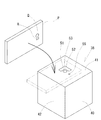
本実施例の読取補助装置39は、図8,9に示すように、筐体40を具備してなる。筐体40は、天板41と側壁42とからなる立方体形状をなしており、底部は開口部43となっている。筐体40の内部には、電源としての電池44と、白色光と赤外光を選択的に照射可能な照明部46と、該照明部46を制御する制御部47とが収容されている。照明部46は、白色光を照射する白色LED48と赤外光を照射する赤外光LED49を基板50に実装してなるものであり、筐体40の底部の方向に白色光又は赤外光を照射するよう配置されている。
As shown in FIGS. 8 and 9, the reading assist
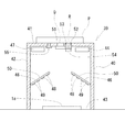
図8,9に示すように、天板41の中央部には、スマートフォンPの背面カメラで筐体40の底部に配置された光学コード1aを撮像するためのカメラ用開口部51が形成される。カメラ用開口部51は、背面カメラのレンズQより一回り大きい径を有する貫通孔である。また、天板41には、カメラ用開口部51の周囲に、平面視L字状をなす照明用開口部52が形成される。照明用開口部52には、内部で光(可視光)を拡散させる導光パネル53が嵌め込まれており。照明用開口部52の直下には、照明用開口部52を透過して導光パネル53で拡散した可視光を検知可能な受光センサ54が配設される。また、天板41には、スマートフォンPの乗載を検知するための動作センサ55が設けられる。動作センサ55は感圧式スイッチであり、スマートフォンPが天板41に載せられている間は、スマートフォンPの重みにより動作センサ55がONとなる。
As shown in FIGS. 8 and 9, a
制御部47は、動作センサ55がOFFの状態、すなわち、スマートフォンPが天板41に載せられていない状態では、照明部46が白色光及び赤外光を照射しないよう制御する。一方、制御部47は、動作センサ55がONの状態、すなわち、スマートフォンPが天板41に載せられている状態では、受光センサ54の検知状態に応じて照明部46に白色光と赤外光のいずれか一方を選択的に照射させる。具体的には、制御部47は、動作センサ55がONであり、かつ、受光センサ54が光を検知している場合には、照明部46に白色光のみを照射させ、動作センサ55がONであり、かつ、受光センサ54が光を検知していない場合には、照明部46に赤外光のみを照射させる。
The
以下に、光学コード1aの可視光記録領域と赤外光記録領域に記録されたデータを、読取補助装置39を用いてスマートフォンPで読み取る方法について説明する。なお、(5)〜(9)の処理は、実施例2で説明した同名の処理と同様の内容をスマートフォンPで実行するだけであるため、詳細な説明は省略する。
(1)光学コードの配置
図9に示すように、光学コード1aが付された薬剤の包装箱を、光学コード1aを上向きにして筐体40の底部に配置する。
(2)スマートフォンの設置
図8,9に示すように、スマートフォンPを天板41の上に載せる。この時、スマートフォンPの背面側カメラのレンズQが、天板41のカメラ用開口部51の真上に位置し、かつ、レンズQの周囲に配設されたLEDライトRが、照明用開口部52の真上に位置するようにスマートフォンPを位置合わせする。なお、この時点では、スマートフォンPのLEDライトRは消灯させておく。
(3)赤外光撮像処理
天板41に載せたスマートフォンPの背面カメラで、カメラ用開口部51を介して底部の光学コード1aを撮像する。この時、動作センサ55はONであり、また、スマートフォンPのLEDライトRは消灯しており、照明用開口部52から光が進入していないため、照明部46から底部の光学コード1aに向けて赤外光が照射されている。すなわち、かかる赤外光撮像処理では、光学コード1aを赤外光で撮像した画像が得られる。
(4)可視光撮像処理
天板41に載せたスマートフォンPのLEDライトRを点灯状態に切り替えた後に、背面カメラで、カメラ用開口部51を介して底部の光学コード1aを撮像する。この時、動作センサ55はONであり、また、LEDライトRが照射する白色光が照明用開口部52から進入して受光センサ54で検知されるため、照明部46から底部の光学コード1aに向けて白色光が照射されている。すなわち、かかる可視光撮像処理では、光学コード1aを可視光で撮像した画像が得られる。
(5)可視光反射特性識別処理
(6)商品情報読取処理
(7)赤外光反射特性識別処理
(8)真贋判定処理
(9)結果出力処理
Hereinafter, a method of reading the data recorded in the visible light recording region and the infrared light recording region of the
(1) Arrangement of Optical Cords As shown in FIG. 9, a drug packaging box to which the
(2) Installation of smartphone As shown in FIGS. 8 and 9, the smartphone P is placed on the
(3) Infrared light imaging process The rear camera of the smartphone P mounted on the
(4) Visible light imaging process After switching the LED light R of the smartphone P mounted on the
(5) Visible light reflection characteristic identification processing (6) Product information reading processing (7) Infrared light reflection characteristic identification processing (8) Authenticity judgment processing (9) Result output processing
このように、本実施例の読取補助装置39とスマートフォンPを用いれば、光学コード1aを可視光で撮像した画像と、赤外光で撮像した画像を得ることができるため、上記実施例2の光学コード1aの可視光記録領域と赤外光記録領域に記録されたデータを、専用の読取装置を使用するよりも低廉に読取可能となる。なお、本実施例では、可視光撮像処理の際に、読取補助装置39の筐体40に配設された照明部46から光学コード1aに白色光を照射しているが、照明部46からの白色光の照射に替えて、スマートフォンPのLEDライトRの白色光で光学コード1aを照らすようにしても良い。
As described above, by using the reading assist
なお、本発明の光学コードは、本発明の趣旨の範囲内で、上記実施例の構成を適宜変更することができる。例えば、上記実施例の光学コードでは、明色モジュールと暗色モジュールのパターンがQRコードの規格に準拠しているが、本発明の光学コードに係る明色モジュールと暗色モジュールのパターンは、QRコード以外の光学コードの規格に準拠していてもよい。具体的には、データマトリックス等のマトリックス型二次元コードや、PDF417等のスタック型二次元コード、バーコード(EAN/JANシンボル)などの規格に準拠させることが提案される。 The optical cord of the present invention can be appropriately modified in the configuration of the above embodiment within the scope of the gist of the present invention. For example, in the optical code of the above embodiment, the patterns of the light color module and the dark color module conform to the QR code standard, but the patterns of the light color module and the dark color module according to the optical code of the present invention are other than the QR code. It may conform to the standard of the optical code of. Specifically, it is proposed to comply with standards such as a matrix type two-dimensional code such as a data matrix, a stack type two-dimensional code such as PDF417, and a barcode (EAN / JAN symbol).
また、上記実施例の光学コードは、薬剤の包装箱に付されるものであるが、本発明の光学コードは、包装箱に限らず、包装箱内部の個包装に付してもよいし、商品タグや商品本体に付してもよい。また、商品単品の包装に限らず、商品を複数個収容した段ボールやパレット、コンテナなどに付してもよい。また、光学コードを付する対象商品は薬剤に限られず、薬剤に限らず様々な商品に使用可能である。具体的には、鞄や財布などの高級ブランド品や、チケット、金券などが挙げられる。また、上記実施例では、光学コードを薬剤の包装箱に直接印刷しているが、包装箱とは別のシートに光学コードを印刷して、包装箱に貼付するようにしてもよい。 Further, the optical cord of the above embodiment is attached to the packaging box of the drug, but the optical cord of the present invention is not limited to the packaging box, and may be attached to the individual packaging inside the packaging box. It may be attached to the product tag or the product body. Further, the packaging is not limited to a single product, and may be attached to a corrugated cardboard, a pallet, a container or the like containing a plurality of products. Further, the target product to which the optical cord is attached is not limited to the drug, and can be used for various products not limited to the drug. Specific examples include luxury brand products such as bags and wallets, tickets, and cash vouchers. Further, in the above embodiment, the optical code is printed directly on the packaging box of the drug, but the optical code may be printed on a sheet different from the packaging box and attached to the packaging box.
また、上記実施例の光学コードでは、個々の暗色モジュールが一種類のインキの層で形成されているが、一つの暗色モジュールを複数種類のインキの層によって形成してもかまわない。なお、暗色モジュールを形成するインキの層は、黒色系のインキに限らず、プロセスインキ等であってもよい。また、暗色モジュールは、印刷インキに限らず、トナーインキ等によって形成することもできる。また、インキの層は、紙基材の表側に積層されていてもよいし、紙基材に表面に染み込んでいてもよい。 Further, in the optical cord of the above embodiment, each dark color module is formed by one kind of ink layer, but one dark color module may be formed by a plurality of kinds of ink layers. The ink layer forming the dark color module is not limited to the black ink, and may be a process ink or the like. Further, the dark color module is not limited to the printing ink, and can be formed by toner ink or the like. Further, the ink layer may be laminated on the front side of the paper base material, or may be impregnated into the surface of the paper base material.
本発明の光学コードは、その複写物において赤外光反射暗色モジュールと赤外光吸収暗色モジュールのパターンが失われることに基づいて、複写物であるか否かを判定するため、複写物の判定基準は上記実施例の構成に限定されず、適宜変更可能である。例えば、実施例2の光学コードにおいて、赤外光反射暗色モジュールと赤外光吸収暗色モジュールの二種類が識別されたことをもって、複写物でないと判定するようにしてもよい。 The optical code of the present invention determines whether or not the copy is a copy based on the loss of the patterns of the infrared light reflection dark color module and the infrared light absorption dark color module in the copy. The standard is not limited to the configuration of the above embodiment, and can be changed as appropriate. For example, in the optical code of the second embodiment, it may be determined that the copy is not a copy when two types of the infrared light reflection dark color module and the infrared light absorption dark color module are identified.
また、上記実施例では、本発明に係る第一のモジュール(赤外光反射暗色モジュール2ba)と第二のモジュール(赤外光吸収暗色モジュール2bb)は、暗色モジュール2bに含まれており、いずれも黒色を呈しているが、本発明に係る第一のモジュールと第二のモジュールは、黒色以外の色を採用してもよい。なお、第一のモジュールと第二のモジュールの色は、完全に一致させる必要はないが、目視で識別が困難な程度に、可視光の反射特性が同等であることが好ましい。
Further, in the above embodiment, the first module (infrared light reflection dark color module 2ba) and the second module (infrared light absorption dark color module 2bb) according to the present invention are included in the
また、上記実施例では、本発明に係る第一のモジュール(赤外光反射暗色モジュール2ba)と第二のモジュール(赤外光吸収暗色モジュール2bb)は、いずれも暗色モジュール2bに含まれているが、本発明に係る第一のモジュールと第二のモジュールは、明色モジュールに含まれていてもかまわない。
Further, in the above embodiment, the first module (infrared light reflection dark color module 2ba) and the second module (infrared light absorption dark color module 2bb) according to the present invention are both included in the
また、上記実施例では、1000nmの波長の赤外光が、本発明に係る所定波長の不可視光に相当しているが、本発明に係る所定波長の不可視光は、1000nm以外の波長の赤外光であってもよいし、紫外光領域の光であってもよい。 Further, in the above embodiment, the infrared light having a wavelength of 1000 nm corresponds to the invisible light having a predetermined wavelength according to the present invention, but the invisible light having a predetermined wavelength according to the present invention is infrared light having a wavelength other than 1000 nm. It may be light or light in the ultraviolet light region.
1,1a,1b 光学コード
2 モジュール
2a 明色モジュール
2b 暗色モジュール
2ba 赤外光反射暗色モジュール(第一のモジュール)
2baa 第一赤外光反射暗色モジュール(第二の不可視光反射暗色モジュール)
2bab 第二赤外光反射暗色モジュール(第一の不可視光反射暗色モジュール)
2bb 赤外光吸収暗色モジュール(第二のモジュール)
3 機能パターン(固定領域)
4 符号化領域
5 位置検出パターン
10 紙基材(明色ベース層)
11a 赤外光透過黒色インキ
11b 赤外光吸収黒色インキ
1,1a,
2baa 1st infrared light reflection dark color module (2nd invisible light reflection dark color module)
2bab Second infrared light reflection dark color module (first invisible light reflection dark color module)
2bb Infrared light absorption dark color module (second module)
3 Functional pattern (fixed area)
4
11a Infrared light transmitting
Claims (13)
明色モジュールと暗色モジュールの少なくとも一方は、所定波長の不可視光の反射率が相違し、かつ、可視光の反射特性が同等である第一のモジュールと第二のモジュールを含み、
可視光を照射した場合と、前記所定波長の不可視光を照射した場合と、で其々異なるモジュールのパターンとして読取可能に記録され、
明色モジュールと暗色モジュールの位置が予め決定され、光学的読取りを補助するパターンを構成する固定領域を備えるものであり、
固定領域に含まれる明色モジュールと暗色モジュールの少なくとも一方は、前記第一のモジュールと前記第二のモジュールとからなり、前記第一のモジュールと前記第二のモジュールの位置が予め決定されていることを特徴とする光学コード。 An optical code that records data by a pattern of multiple bright color modules with high visible light reflectance and multiple dark color modules with low visible light reflectance.
At least one light colored module and dark modules, invisible light reflectance of a predetermined wavelength are different, and, reflection characteristics of visible light includes a first module and a second module Ru equivalent der,
It is readable and recorded as a different module pattern depending on whether it is irradiated with visible light or invisible light of the predetermined wavelength .
The positions of the light and dark modules are predetermined and include a fixed area that constitutes a pattern that assists in optical reading.
At least one light colored module and dark modules included in the fixed area is made with the first module and the second module, the position of said first module the second module that has been previously determined An optical cord characterized by that.
前記第一のモジュールは、前記第二のモジュールよりも前記所定波長の不可視光の反射率が高く、 The first module has a higher reflectance of invisible light having the predetermined wavelength than the second module.
前記固定領域は、複数の前記第一のモジュールからなる矩形状の中央部と、複数の前記第二のモジュールからなる外周部とを具備する位置検出パターンを備えることを特徴とする請求項1に記載の光学コード。 The first aspect of the present invention is characterized in that the fixed region includes a position detection pattern including a rectangular central portion composed of the plurality of the first modules and an outer peripheral portion composed of the plurality of the second modules. Described optical code.
前記第一のモジュールと前記第二のモジュールのパターンによって記録されるデータは、所定内容の情報を暗号化したデータを含むことを特徴とする請求項4に記載の光学コード。 The first module and the second module are included in one of a light color module and a dark color module.
The optical code according to claim 4 , wherein the data recorded by the patterns of the first module and the second module includes data in which information having a predetermined content is encrypted.
前記第一のモジュール及び前記第二のモジュールは、暗色モジュールに含まれており、
前記第一のモジュールの形成部位には、前記明色ベース層の表側に、前記所定波長の不可視光を透過し、かつ暗色を呈する第一の暗色層が形成されており、
前記第二のモジュールの形成部位には、前記明色ベース層の表側に、前記所定波長の不可視光を吸収し、かつ暗色を呈する第二の暗色層が形成されており、
前記第一のモジュールは、前記第二のモジュールに比べて前記所定波長の不可視光の反射率が高いことを特徴とする請求項1乃至請求項5のいずれか1項に記載の光学コード。 The dark color module is formed on the front side of a light color base layer having high reflectance of visible light and invisible light having a predetermined wavelength.
The first module and the second module are included in the dark color module.
At the formation site of the first module, a first dark color layer that transmits invisible light of a predetermined wavelength and exhibits a dark color is formed on the front side of the light color base layer.
At the formation site of the second module, a second dark color layer that absorbs invisible light of the predetermined wavelength and exhibits a dark color is formed on the front side of the light color base layer.
The optical cord according to any one of claims 1 to 5 , wherein the first module has a higher reflectance of invisible light having a predetermined wavelength than the second module.
前記第二の暗色層は、少なくとも、前記所定波長の不可視光を吸収する不可視光吸収層によって形成されていることを特徴とする請求項6に記載の光学コード。 The first dark color layer is formed by an invisible light transmitting layer that transmits invisible light having a predetermined wavelength.
The optical cord according to claim 6 , wherein the second dark color layer is formed by at least an invisible light absorbing layer that absorbs invisible light having a predetermined wavelength.
前記所定波長の不可視光の反射率と、前記所定波長の不可視光とは異なる別波長の不可視光の反射率が高い第一の不可視光反射暗色モジュールと、
前記所定波長の不可視光の反射率が高く、前記別波長の不可視光の反射率が低い第二の不可視光反射暗色モジュールとを含み、
第一の不可視光反射暗色モジュールは、前記明色ベース層の表側に形成された、前記所定波長の不可視光と前記別波長の不可視光の両方を透過する層によって暗色に形成され、
第二の不可視光反射暗色モジュールは、前記明色ベース層の表側に形成された、前記所定波長の不可視光を透過し、前記別波長の不可視光を吸収する層によって暗色に形成されていることを特徴とする請求項6又は請求項7に記載の光学コード。 The first module is
A first invisible light reflection dark color module having high reflectance of invisible light having a predetermined wavelength and invisible light having a wavelength different from that of invisible light having a predetermined wavelength.
It includes a second invisible light reflecting dark color module having a high reflectance of the invisible light of a predetermined wavelength and a low reflectance of the invisible light of another wavelength.
The first invisible light reflection dark color module is formed in dark color by a layer formed on the front side of the light color base layer and transmitting both invisible light having a predetermined wavelength and invisible light having another wavelength.
The second invisible light reflection dark color module is formed in a dark color by a layer formed on the front side of the light color base layer, which transmits invisible light of the predetermined wavelength and absorbs the invisible light of another wavelength. The optical cord according to claim 6 or 7.
前記第一のモジュール及び前記第二のモジュールは、暗色モジュールに含まれており、
前記第一のモジュールの形成部位には、前記明色ベース層の表側に、前記所定波長の不可視光を部分的に透過し、かつ暗色を呈する第一の暗色層が形成されており、
前記第二のモジュールの形成部位には、前記明色ベース層の表側に、前記所定波長の不可視光を吸収し、かつ暗色を呈する第二の暗色層が形成されており、
前記第一のモジュールは、前記第二のモジュールに比べて前記所定波長の不可視光の反射率が高く、前記明色モジュールに比べて前記所定波長の不可視光の反射率が低いことを特徴とする請求項1乃至請求項5のいずれか1項に記載の光学コード。 The dark color module is formed on the front side of a light color base layer having high reflectance of visible light and invisible light having a predetermined wavelength.
The first module and the second module are included in the dark color module.
At the formation site of the first module, a first dark color layer that partially transmits invisible light of a predetermined wavelength and exhibits a dark color is formed on the front side of the light color base layer.
At the formation site of the second module, a second dark color layer that absorbs invisible light of the predetermined wavelength and exhibits a dark color is formed on the front side of the light color base layer.
The first module is characterized in that the reflectance of the invisible light having the predetermined wavelength is higher than that of the second module and the reflectance of the invisible light having the predetermined wavelength is lower than that of the bright color module. The optical cord according to any one of claims 1 to 5.
明色モジュールと暗色モジュールのパターンによって記録するデータは、商品管理に用いる情報を含むことを特徴とする請求項1乃至請求項9のいずれか1項に記載の光学コード。 An optical cord attached to at least one of a product, a product package, and a product tag.
The optical code according to any one of claims 1 to 9 , wherein the data recorded by the patterns of the light color module and the dark color module includes information used for product management.
所要のデータを記録する前記光学コードの、明色モジュールと暗色モジュールのパターンを決定する第一のステップと、
第一のステップで決定した各暗色モジュールについて、前記所定波長の不可視光の反射率が高い前記第一のモジュールと、前記所定波長の不可視光の反射率が低い前記第二のモジュールのいずれかに決定する第二のステップと、
可視光及び前記所定波長の不可視光の反射率の高い明色ベース層の表側に、前記所定波長の不可視光を透過する第一の暗色層を設けることにより前記第一のモジュールを形成するとともに、該明色ベース層の表側に前記所定波長の不可視光を吸収する第二の暗色層を設けることにより前記第二のモジュールを形成する第三のステップと
を含むことを特徴とする光学コードの作成方法。 The method for creating an optical cord according to claim 1.
The first step of determining the pattern of the light-colored module and the dark-colored module of the optical code for recording the required data, and
Each dark modules determined in the first step, and the invisible light reflectance of a given wavelength is high the first module, to one of the invisible light reflectance of a predetermined wavelength is lower the second module The second step to decide and
The first module is formed by providing a first dark color layer that transmits the invisible light of the predetermined wavelength on the front side of the bright color base layer having high reflectance of the visible light and the invisible light of the predetermined wavelength. Fabrication of an optical cord comprising a third step of forming the second module by providing a second dark layer that absorbs invisible light of a predetermined wavelength on the front side of the light color base layer. Method.
可視光で前記光学コードを撮像する可視光撮像ステップと、
前記所定波長の不可視光で前記光学コードを撮像する不可視光撮像ステップと、
可視光撮像ステップで撮像した画像に基づいて、前記光学コードに含まれる少なくとも一部のモジュールについて、明色モジュールと暗色モジュールのいずれであるかを識別する可視光識別ステップと、
不可視光撮像ステップで撮像した画像に基づいて、前記光学コードに含まれる少なくとも一部のモジュールについて、前記所定波長の不可視光の反射率の高いモジュールと低いモジュールのいずれであるかを識別する不可視光識別ステップと、
可視光識別ステップと不可視光識別ステップの結果に基づいて、少なくとも一部のモジュールについて、前記第一のモジュールと前記第二のモジュールのいずれであるかを識別する不可視光モジュール識別ステップと、
少なくとも不可視光モジュール識別ステップの結果に基づいて、前記固定領域に、前記第一のモジュールと前記第二のモジュールからなる所定のパターンが存在するか否かを判定することにより、前記光学コードの真贋を判定する真贋判定ステップと
を含むことを特徴とする光学コードの真贋判定方法。 The method for determining the authenticity of an optical cord according to claim 1.
A visible light imaging step of imaging the optical code with visible light,
An invisible light imaging step of imaging the optical code with the invisible light of the predetermined wavelength,
A visible light identification step that identifies whether at least a part of the modules included in the optical code is a light color module or a dark color module based on the image captured in the visible light imaging step.
Invisible light that identifies at least a part of the modules included in the optical code as a module having a high reflectance or a module having a low reflectance of the invisible light having a predetermined wavelength, based on the image captured in the invisible light imaging step. Identification step and
Based on the results of the visible light identification step and the invisible light identification step, the invisible light module identification step for identifying at least a part of the modules as either the first module or the second module, and the invisible light module identification step.
The authenticity of the optical cord is determined by determining whether or not a predetermined pattern consisting of the first module and the second module exists in the fixed region based on at least the result of the invisible light module identification step. An authenticity determination method for an optical code, which comprises an authenticity determination step for determining.
少なくとも天板と側壁とを有し、底部に前記光学コードを配置可能に構成された筐体と、
該筐体の内部に配設されて、前記所定波長の不可視光を該筐体の底部に照射可能な照射部と、
該照射部による前記所定波長の不可視光の照射を制御する制御部と
を備え、
前記筐体の天板には、少なくとも可視光及び前記所定波長の不可視光が透過可能なカメラ用開口部が形成されるとともに、該カメラ用開口部の周囲に少なくとも可視光が透過可能な照明用開口部が形成されており、
さらに、前記筐体の内部に、前記照明用開口部を透過する光を検知する受光センサを備え、
前記制御部は、前記受光センサが前記照明用開口部を透過する光を検知していないことを条件に、前記照射部による前記所定波長の不可視光の照射を許容し、少なくとも、前記受光センサが前記照明用開口部を透過する光を検知している場合は、前記照射部による前記所定波長の不可視光の照射を許容しないことを特徴とする読取補助装置。 Data is recorded by a pattern of a plurality of bright color modules having a high visible light reflectance and a plurality of dark color modules having a low visible light reflectance, and at least one of the light color module and the dark color module is predetermined. As a pattern of modules that include a first module and a second module having different reflectances of invisible light of a wavelength, and are irradiated with visible light and invisible light of a predetermined wavelength, respectively. A pattern of a module that becomes readable when irradiating an optical code characterized by being readable and recorded with visible light, and a pattern of a module that becomes readable when irradiating invisible light of the predetermined wavelength. Is a reading assist device for making a smartphone read
A housing having at least a top plate and a side wall so that the optical cord can be arranged at the bottom.
An irradiation unit that is disposed inside the housing and can irradiate the bottom of the housing with invisible light having the predetermined wavelength.
It is provided with a control unit that controls irradiation of invisible light having the predetermined wavelength by the irradiation unit.
A camera opening capable of transmitting at least visible light and invisible light having a predetermined wavelength is formed on the top plate of the housing, and at least visible light can be transmitted around the camera opening for illumination. An opening is formed
Further, a light receiving sensor for detecting light transmitted through the lighting opening is provided inside the housing.
The control unit allows the irradiation unit to irradiate invisible light having the predetermined wavelength on the condition that the light receiving sensor does not detect the light transmitted through the illumination opening, and at least the light receiving sensor allows the light receiving sensor to irradiate the invisible light having the predetermined wavelength. A reading assisting device characterized in that when the light transmitted through the illumination opening is detected, the irradiation of the invisible light having the predetermined wavelength by the irradiation unit is not allowed.
Priority Applications (3)
| Application Number | Priority Date | Filing Date | Title |
|---|---|---|---|
| KR1020187020134A KR20190020639A (en) | 2015-12-17 | 2016-12-19 | An optical code, a method of producing an optical code, a method of judging authenticity of an optical code, an optical code reading apparatus and a reading aid apparatus |
| PCT/JP2016/087833 WO2017104856A1 (en) | 2015-12-17 | 2016-12-19 | Optical code, optical code creation method, optical code authenticity determination method, optical code reading device and reading assistance device |
| US16/063,307 US10769397B2 (en) | 2015-12-17 | 2016-12-19 | Optical code, method of producing optical code, method of authenticating optical code, device for reading optical code, and reading assist device |
Applications Claiming Priority (2)
| Application Number | Priority Date | Filing Date | Title |
|---|---|---|---|
| JP2015246195 | 2015-12-17 | ||
| JP2015246195 | 2015-12-17 |
Publications (2)
| Publication Number | Publication Date |
|---|---|
| JP2017117454A JP2017117454A (en) | 2017-06-29 |
| JP6927559B2 true JP6927559B2 (en) | 2021-09-01 |
Family
ID=59234389
Family Applications (4)
| Application Number | Title | Priority Date | Filing Date |
|---|---|---|---|
| JP2016241913A Pending JP2017117455A (en) | 2015-12-17 | 2016-12-14 | Optical code, creation method of optical code, reading method of optical code, and barcode reading device |
| JP2016241912A Active JP6927559B2 (en) | 2015-12-17 | 2016-12-14 | Optical code, optical code creation method, optical code authenticity determination method, optical code reader, and reading aid |
| JP2017114119A Active JP6845571B2 (en) | 2015-12-17 | 2017-06-09 | Optical code, optical code creation method, optical code reading method, and barcode reader |
| JP2017117803A Active JP6927569B2 (en) | 2015-12-17 | 2017-06-15 | Optical cord, optical cord printing device, register, and optical cord printing method |
Family Applications Before (1)
| Application Number | Title | Priority Date | Filing Date |
|---|---|---|---|
| JP2016241913A Pending JP2017117455A (en) | 2015-12-17 | 2016-12-14 | Optical code, creation method of optical code, reading method of optical code, and barcode reading device |
Family Applications After (2)
| Application Number | Title | Priority Date | Filing Date |
|---|---|---|---|
| JP2017114119A Active JP6845571B2 (en) | 2015-12-17 | 2017-06-09 | Optical code, optical code creation method, optical code reading method, and barcode reader |
| JP2017117803A Active JP6927569B2 (en) | 2015-12-17 | 2017-06-15 | Optical cord, optical cord printing device, register, and optical cord printing method |
Country Status (3)
| Country | Link |
|---|---|
| US (2) | US11487961B2 (en) |
| JP (4) | JP2017117455A (en) |
| KR (1) | KR20190020639A (en) |
Families Citing this family (40)
| Publication number | Priority date | Publication date | Assignee | Title |
|---|---|---|---|---|
| KR101710050B1 (en) * | 2014-10-30 | 2017-02-24 | 밍 추이 | Image identification systems and method |
| US10467840B2 (en) * | 2016-12-07 | 2019-11-05 | Ashish Anand | Method for automated authentication of a security label |
| CN110770802A (en) * | 2017-06-19 | 2020-02-07 | 昕诺飞控股有限公司 | Sensor assembly and device comprising such a sensor assembly. |
| DE102017120093A1 (en) * | 2017-08-31 | 2019-02-28 | Erich Utsch Ag | Blocking tool and embossing press for embossing a legend in a license plate, and method for verifying a block tool |
| WO2019094274A1 (en) * | 2017-11-07 | 2019-05-16 | Verifyme, Inc. | Dual code authentication process |
| JP2021501918A (en) * | 2017-11-07 | 2021-01-21 | スリーエム イノベイティブ プロパティズ カンパニー | Optical film and system containing it |
| CN110378453A (en) * | 2018-04-13 | 2019-10-25 | 乌镇中品安(桐乡)科技有限公司 | Color trellis code and its recognition methods |
| EP3557481B1 (en) | 2018-04-20 | 2023-02-22 | Nxp B.V. | Method for providing a code pattern |
| US20200033560A1 (en) * | 2018-07-30 | 2020-01-30 | Apple Inc. | Electronic Device System With Supplemental Lenses |
| CN108764424B (en) * | 2018-08-10 | 2024-03-22 | 北京龙贝世纪科技股份有限公司 | Textile two-dimensional code mark and manufacturing method thereof |
| JP7119799B2 (en) * | 2018-09-07 | 2022-08-17 | 株式会社デンソーウェーブ | Authenticity judgment system |
| EP3872681B1 (en) * | 2018-10-23 | 2024-02-14 | Denso Wave Incorporated | Information-code reading device |
| KR102008934B1 (en) * | 2018-11-26 | 2019-08-08 | 한국조폐공사 | Plastic product comprising photoluminescent material and method for determining authenticity of the same |
| JP7159911B2 (en) * | 2019-02-27 | 2022-10-25 | 京セラドキュメントソリューションズ株式会社 | Image processing device and image forming device |
| JP7243293B2 (en) * | 2019-02-28 | 2023-03-22 | ブラザー工業株式会社 | Printer and program |
| JP7274202B2 (en) * | 2019-02-28 | 2023-05-16 | 株式会社テララコード研究所 | Optical code creation program, optical code reading authentication program, optical code authentication system, payment system, printed matter manufacturing method, and optical code authentication method |
| US10509991B1 (en) | 2019-03-18 | 2019-12-17 | Capital One Services, Llc | Detection of images in relation to targets based on colorspace transformation techniques and utilizing infrared light |
| US10496911B1 (en) | 2019-03-18 | 2019-12-03 | Capital One Services, Llc | Detection of images in relation to targets based on colorspace transformation techniques and utilizing ultraviolet and infrared light |
| US10496862B1 (en) | 2019-03-18 | 2019-12-03 | Capital One Services, Llc | Detection of images in relation to targets based on colorspace transformation techniques and utilizing ultraviolet light |
| US10534948B1 (en) | 2019-03-18 | 2020-01-14 | Capital One Services, Llc | Optimizing detection of images in relation to targets based on colorspace transformation techniques |
| US10523420B1 (en) | 2019-04-18 | 2019-12-31 | Capital One Services, Llc | Transmitting encoded data along transmission mediums based on colorspace schemes |
| US10504013B1 (en) | 2019-04-24 | 2019-12-10 | Capital One Services, Llc | Colorspace encoding multimedia data on a physical page |
| US10529300B1 (en) | 2019-06-20 | 2020-01-07 | Capital One Services, Llc | Adaptive image display based on colorspace conversions |
| JP7310354B2 (en) * | 2019-06-25 | 2023-07-19 | 株式会社リコー | Image processing device, image forming device and image processing method |
| US10614635B1 (en) | 2019-07-25 | 2020-04-07 | Capital One Services, Llc | Augmented reality system with color-based fiducial marker |
| US20220348034A1 (en) * | 2019-09-13 | 2022-11-03 | Kyodo Printing Co., Ltd. | Printed object |
| US10833852B1 (en) * | 2019-10-03 | 2020-11-10 | Capital One Services, Llc | Encoded data along tape based on colorspace schemes |
| JP6931935B2 (en) | 2019-10-11 | 2021-09-08 | 株式会社テララコード研究所 | Two-dimensional symbols and how to read two-dimensional symbols |
| US10715183B1 (en) * | 2019-10-25 | 2020-07-14 | Capital One Services, Llc | Data encoding with error-correcting code pursuant to colorspace schemes |
| US10867226B1 (en) | 2019-11-04 | 2020-12-15 | Capital One Services, Llc | Programmable logic array and colorspace conversions |
| US10762371B1 (en) | 2019-11-14 | 2020-09-01 | Capital One Services, Llc | Object detection techniques using colorspace conversions |
| WO2021108364A1 (en) * | 2019-11-27 | 2021-06-03 | Stratio | Scanner for multi-dimensional code and labels |
| US10878600B1 (en) | 2019-12-10 | 2020-12-29 | Capital One Services, Llc | Augmented reality system with color-based fiducial marker utilizing local adaptive technology |
| WO2021119067A1 (en) * | 2019-12-10 | 2021-06-17 | Fenwal, Inc. | Positive image bar code on flexible medical solution container |
| US11314997B1 (en) | 2020-04-18 | 2022-04-26 | Rf Code, Inc. | Barcode tag, and method and system employing same, for tracking electronic equipment |
| US11302036B2 (en) | 2020-08-19 | 2022-04-12 | Capital One Services, Llc | Color conversion between color spaces using reduced dimension embeddings |
| KR102557786B1 (en) * | 2020-09-28 | 2023-07-20 | (주)오상테크놀로지 | Discriminating system for a genuine article of forest products using artificial intelligence |
| US20220237396A1 (en) * | 2021-01-26 | 2022-07-28 | Nec Corporation Of America | Invisible coated infrared patterns |
| KR20230044775A (en) * | 2021-09-27 | 2023-04-04 | 김학수 | Multifunctional Recognition Device and Recognition System Using the Same |
| WO2023158854A2 (en) | 2022-02-21 | 2023-08-24 | Rf Code, Inc. | System, apparatus, and method for monitoring edge compute sites |
Family Cites Families (33)
| Publication number | Priority date | Publication date | Assignee | Title |
|---|---|---|---|---|
| US4544836A (en) * | 1982-12-22 | 1985-10-01 | American District Telegraph Company | Optically-based access control system |
| JP2695943B2 (en) * | 1989-09-30 | 1998-01-14 | 東洋インキ製造株式会社 | Barcode record and detection method |
| US5726435A (en) * | 1994-03-14 | 1998-03-10 | Nippondenso Co., Ltd. | Optically readable two-dimensional code and method and apparatus using the same |
| JP2938338B2 (en) | 1994-03-14 | 1999-08-23 | 株式会社デンソー | Two-dimensional code |
| US6119943A (en) * | 1994-12-12 | 2000-09-19 | Moore Business Forms, Inc. | Multi-layer bar code arrangement using wavelength separation |
| JP3827763B2 (en) * | 1996-03-06 | 2006-09-27 | 大日本印刷株式会社 | Infrared symbol discrimination reader |
| US6398117B1 (en) * | 2000-01-14 | 2002-06-04 | Hewlett-Packard Co. | Method and system for combining bar codes of different encoding dimensions |
| US7536553B2 (en) * | 2001-05-10 | 2009-05-19 | Pitney Bowes Inc. | Method and system for validating a security marking |
| JP2005182582A (en) * | 2003-12-22 | 2005-07-07 | Toshiba Corp | Print image verification device and print image verification method |
| US7264169B2 (en) * | 2004-08-02 | 2007-09-04 | Idx, Inc. | Coaligned bar codes and validation means |
| JP4604160B2 (en) * | 2005-03-03 | 2010-12-22 | 独立行政法人 国立印刷局 | Method for producing authentication medium and authentication method therefor |
| JP4374331B2 (en) | 2005-03-25 | 2009-12-02 | 環境化学株式会社 | Image generating apparatus, program, and recording medium |
| JP4665710B2 (en) * | 2005-10-21 | 2011-04-06 | 株式会社デンソーウェーブ | Information code carrier |
| JP4106377B2 (en) * | 2005-12-16 | 2008-06-25 | インターナショナル・ビジネス・マシーンズ・コーポレーション | Apparatus, method, and program for extracting invisible information |
| JP2007193387A (en) * | 2006-01-17 | 2007-08-02 | Dainippon Printing Co Ltd | Security information medium reader |
| JP3953501B1 (en) * | 2006-03-03 | 2007-08-08 | 株式会社バンダイナムコゲームス | Program, information storage medium, two-dimensional code generation system, image generation system, and two-dimensional code |
| JP5194285B2 (en) * | 2006-04-10 | 2013-05-08 | 北日本港湾コンサルタント株式会社 | Identification system for forged or counterfeit products |
| JP4959719B2 (en) * | 2006-12-21 | 2012-06-27 | インターナショナル・ビジネス・マシーンズ・コーポレーション | Method and system for acquiring simulation parameters in invisible code printing support system |
| US8905313B2 (en) * | 2007-04-12 | 2014-12-09 | Honeywell International Inc. | Method and system for creating and reading multi-color co-planar emissive indicia using printable dyes and pigments |
| US8162222B2 (en) * | 2008-01-25 | 2012-04-24 | Intermec Ip Corp. | System and method for identifying erasures in a 2D symbol |
| JP5083676B2 (en) | 2010-02-16 | 2012-11-28 | 株式会社デンソーウェーブ | Reading system and optical information reading apparatus |
| JP5790068B2 (en) | 2010-11-30 | 2015-10-07 | 株式会社デンソーウェーブ | Information code reading system and information code reading device |
| EP2458527A3 (en) | 2010-11-30 | 2014-03-26 | Denso Wave Incorporated | System for reading information code and medium on which information code is formed |
| JP2013004024A (en) * | 2011-06-21 | 2013-01-07 | Kobayashi Create Co Ltd | Two-dimensional code for preventing duplication |
| US8616460B2 (en) * | 2011-07-13 | 2013-12-31 | Eastman Kodak Company | Method for providing dynamic optical illusion images |
| JP5699851B2 (en) * | 2011-08-11 | 2015-04-15 | コニカミノルタ株式会社 | Two-dimensional barcode providing device, two-dimensional barcode analyzing device, two-dimensional barcode providing method, two-dimensional barcode analyzing method, computer program, two-dimensional barcode, and paper |
| US8931701B2 (en) * | 2011-09-29 | 2015-01-13 | Spectra Systems Corporation | Methods and systems for authenticating and tracking objects |
| US9167165B2 (en) * | 2012-08-01 | 2015-10-20 | Bae Systems Information And Electronic Systems Integration Inc. | Visual communications system employing video imagery |
| JP5850411B2 (en) * | 2012-09-27 | 2016-02-03 | 株式会社デンソーウェーブ | Information code |
| US9105973B2 (en) * | 2013-03-14 | 2015-08-11 | South Dakota Board Of Regents | Optically scannable code antenna |
| US10358569B2 (en) * | 2013-03-15 | 2019-07-23 | South Dakota Board Of Regents | Systems and methods for printing patterns using near infrared upconverting inks |
| JP5914579B2 (en) * | 2014-06-16 | 2016-05-11 | 株式会社トッパンTdkレーベル | Concealment target information concealment method, concealment target information concealment device, program, concealment target information extraction method, and concealment target information extraction device |
| US10496911B1 (en) * | 2019-03-18 | 2019-12-03 | Capital One Services, Llc | Detection of images in relation to targets based on colorspace transformation techniques and utilizing ultraviolet and infrared light |
-
2016
- 2016-12-14 JP JP2016241913A patent/JP2017117455A/en active Pending
- 2016-12-14 JP JP2016241912A patent/JP6927559B2/en active Active
- 2016-12-19 KR KR1020187020134A patent/KR20190020639A/en unknown
- 2016-12-19 US US15/383,896 patent/US11487961B2/en active Active
- 2016-12-19 US US16/063,307 patent/US10769397B2/en active Active
-
2017
- 2017-06-09 JP JP2017114119A patent/JP6845571B2/en active Active
- 2017-06-15 JP JP2017117803A patent/JP6927569B2/en active Active
Also Published As
| Publication number | Publication date |
|---|---|
| JP2018097840A (en) | 2018-06-21 |
| JP2017117454A (en) | 2017-06-29 |
| JP2017117455A (en) | 2017-06-29 |
| JP6845571B2 (en) | 2021-03-17 |
| US10769397B2 (en) | 2020-09-08 |
| US11487961B2 (en) | 2022-11-01 |
| JP6927569B2 (en) | 2021-09-01 |
| JP2017182835A (en) | 2017-10-05 |
| US20170200035A1 (en) | 2017-07-13 |
| KR20190020639A (en) | 2019-03-04 |
| US20190018994A1 (en) | 2019-01-17 |
Similar Documents
| Publication | Publication Date | Title |
|---|---|---|
| JP6927559B2 (en) | Optical code, optical code creation method, optical code authenticity determination method, optical code reader, and reading aid | |
| WO2017104856A1 (en) | Optical code, optical code creation method, optical code authenticity determination method, optical code reading device and reading assistance device | |
| CN107206829B (en) | The method for protecting invisible 2D bar code and print image | |
| EP3013595B1 (en) | Security coding system & marker, optoelectronic scanner and method of coding articles | |
| JPWO2005115575A1 (en) | Data recording medium and game device | |
| WO2006130444A2 (en) | Method and apparatus for authenticating products | |
| JP6128749B2 (en) | Optical reader, optical reading method and program | |
| JP4935019B2 (en) | Article registration apparatus, article registration program, and authentication system | |
| JP6185801B2 (en) | Determination system and determination apparatus | |
| JP4717914B2 (en) | recoding media | |
| JP4334329B2 (en) | recoding media | |
| US7633651B2 (en) | Generating a non-reproducible printed image | |
| JP2008310691A (en) | Method for identifying photo identification | |
| JP2017001246A (en) | Optically-reading document and authenticity determination method of the same | |
| JP5724774B2 (en) | Information code reading system and information code reading device | |
| JP2018060331A (en) | Information code reader and system thereof and authenticity determination method of media | |
| JP2007136838A (en) | Printed matter for certification and certifying method of the same | |
| JP4572659B2 (en) | Anti-counterfeit card and reading method thereof | |
| JP6334333B2 (en) | Information recording medium and image processing apparatus | |
| JP6003335B2 (en) | Information recording medium reading method and information recording medium | |
| KR20070035519A (en) | Data recording medium and game apparatus | |
| WO2012002444A1 (en) | Method and apparatus for manufacturing identification medium | |
| KR200324861Y1 (en) | Optical interpretation card and sheet for sensing to be changed and copyed by injustice conduct | |
| JP2003011483A (en) | Information possessing medium and deciding method of genuineness of information possessing medium | |
| JP2015176614A (en) | Inspection method of information recording medium and information recording medium |
Legal Events
| Date | Code | Title | Description |
|---|---|---|---|
| A621 | Written request for application examination |
Free format text: JAPANESE INTERMEDIATE CODE: A621 Effective date: 20191209 |
|
| A131 | Notification of reasons for refusal |
Free format text: JAPANESE INTERMEDIATE CODE: A131 Effective date: 20210202 |
|
| A601 | Written request for extension of time |
Free format text: JAPANESE INTERMEDIATE CODE: A601 Effective date: 20210330 |
|
| A521 | Request for written amendment filed |
Free format text: JAPANESE INTERMEDIATE CODE: A523 Effective date: 20210526 |
|
| TRDD | Decision of grant or rejection written | ||
| A01 | Written decision to grant a patent or to grant a registration (utility model) |
Free format text: JAPANESE INTERMEDIATE CODE: A01 Effective date: 20210629 |
|
| A61 | First payment of annual fees (during grant procedure) |
Free format text: JAPANESE INTERMEDIATE CODE: A61 Effective date: 20210729 |
|
| R150 | Certificate of patent or registration of utility model |
Ref document number: 6927559 Country of ref document: JP Free format text: JAPANESE INTERMEDIATE CODE: R150 |