JP7274202B2 - Optical code creation program, optical code reading authentication program, optical code authentication system, payment system, printed matter manufacturing method, and optical code authentication method - Google Patents
Optical code creation program, optical code reading authentication program, optical code authentication system, payment system, printed matter manufacturing method, and optical code authentication method Download PDFInfo
- Publication number
- JP7274202B2 JP7274202B2 JP2019035464A JP2019035464A JP7274202B2 JP 7274202 B2 JP7274202 B2 JP 7274202B2 JP 2019035464 A JP2019035464 A JP 2019035464A JP 2019035464 A JP2019035464 A JP 2019035464A JP 7274202 B2 JP7274202 B2 JP 7274202B2
- Authority
- JP
- Japan
- Prior art keywords
- optical code
- public key
- recording area
- recorded
- module
- Prior art date
- Legal status (The legal status is an assumption and is not a legal conclusion. Google has not performed a legal analysis and makes no representation as to the accuracy of the status listed.)
- Active
Links
Images


Classifications
-
- G—PHYSICS
- G06—COMPUTING; CALCULATING OR COUNTING
- G06F—ELECTRIC DIGITAL DATA PROCESSING
- G06F21/00—Security arrangements for protecting computers, components thereof, programs or data against unauthorised activity
- G06F21/60—Protecting data
- G06F21/64—Protecting data integrity, e.g. using checksums, certificates or signatures
-
- G—PHYSICS
- G06—COMPUTING; CALCULATING OR COUNTING
- G06K—GRAPHICAL DATA READING; PRESENTATION OF DATA; RECORD CARRIERS; HANDLING RECORD CARRIERS
- G06K19/00—Record carriers for use with machines and with at least a part designed to carry digital markings
- G06K19/06—Record carriers for use with machines and with at least a part designed to carry digital markings characterised by the kind of the digital marking, e.g. shape, nature, code
- G06K19/06009—Record carriers for use with machines and with at least a part designed to carry digital markings characterised by the kind of the digital marking, e.g. shape, nature, code with optically detectable marking
- G06K19/06037—Record carriers for use with machines and with at least a part designed to carry digital markings characterised by the kind of the digital marking, e.g. shape, nature, code with optically detectable marking multi-dimensional coding
-
- G—PHYSICS
- G06—COMPUTING; CALCULATING OR COUNTING
- G06K—GRAPHICAL DATA READING; PRESENTATION OF DATA; RECORD CARRIERS; HANDLING RECORD CARRIERS
- G06K7/00—Methods or arrangements for sensing record carriers, e.g. for reading patterns
- G06K7/10—Methods or arrangements for sensing record carriers, e.g. for reading patterns by electromagnetic radiation, e.g. optical sensing; by corpuscular radiation
- G06K7/14—Methods or arrangements for sensing record carriers, e.g. for reading patterns by electromagnetic radiation, e.g. optical sensing; by corpuscular radiation using light without selection of wavelength, e.g. sensing reflected white light
- G06K7/1404—Methods for optical code recognition
- G06K7/1408—Methods for optical code recognition the method being specifically adapted for the type of code
- G06K7/1417—2D bar codes
-
- G—PHYSICS
- G06—COMPUTING; CALCULATING OR COUNTING
- G06Q—INFORMATION AND COMMUNICATION TECHNOLOGY [ICT] SPECIALLY ADAPTED FOR ADMINISTRATIVE, COMMERCIAL, FINANCIAL, MANAGERIAL OR SUPERVISORY PURPOSES; SYSTEMS OR METHODS SPECIALLY ADAPTED FOR ADMINISTRATIVE, COMMERCIAL, FINANCIAL, MANAGERIAL OR SUPERVISORY PURPOSES, NOT OTHERWISE PROVIDED FOR
- G06Q20/00—Payment architectures, schemes or protocols
- G06Q20/30—Payment architectures, schemes or protocols characterised by the use of specific devices or networks
- G06Q20/32—Payment architectures, schemes or protocols characterised by the use of specific devices or networks using wireless devices
- G06Q20/327—Short range or proximity payments by means of M-devices
- G06Q20/3274—Short range or proximity payments by means of M-devices using a pictured code, e.g. barcode or QR-code, being displayed on the M-device
-
- G—PHYSICS
- G06—COMPUTING; CALCULATING OR COUNTING
- G06Q—INFORMATION AND COMMUNICATION TECHNOLOGY [ICT] SPECIALLY ADAPTED FOR ADMINISTRATIVE, COMMERCIAL, FINANCIAL, MANAGERIAL OR SUPERVISORY PURPOSES; SYSTEMS OR METHODS SPECIALLY ADAPTED FOR ADMINISTRATIVE, COMMERCIAL, FINANCIAL, MANAGERIAL OR SUPERVISORY PURPOSES, NOT OTHERWISE PROVIDED FOR
- G06Q20/00—Payment architectures, schemes or protocols
- G06Q20/30—Payment architectures, schemes or protocols characterised by the use of specific devices or networks
- G06Q20/32—Payment architectures, schemes or protocols characterised by the use of specific devices or networks using wireless devices
- G06Q20/327—Short range or proximity payments by means of M-devices
- G06Q20/3276—Short range or proximity payments by means of M-devices using a pictured code, e.g. barcode or QR-code, being read by the M-device
-
- G—PHYSICS
- G09—EDUCATION; CRYPTOGRAPHY; DISPLAY; ADVERTISING; SEALS
- G09C—CIPHERING OR DECIPHERING APPARATUS FOR CRYPTOGRAPHIC OR OTHER PURPOSES INVOLVING THE NEED FOR SECRECY
- G09C5/00—Ciphering apparatus or methods not provided for in the preceding groups, e.g. involving the concealment or deformation of graphic data such as designs, written or printed messages
-
- H—ELECTRICITY
- H04—ELECTRIC COMMUNICATION TECHNIQUE
- H04L—TRANSMISSION OF DIGITAL INFORMATION, e.g. TELEGRAPHIC COMMUNICATION
- H04L9/00—Cryptographic mechanisms or cryptographic arrangements for secret or secure communications; Network security protocols
- H04L9/30—Public key, i.e. encryption algorithm being computationally infeasible to invert or user's encryption keys not requiring secrecy
-
- H—ELECTRICITY
- H04—ELECTRIC COMMUNICATION TECHNIQUE
- H04L—TRANSMISSION OF DIGITAL INFORMATION, e.g. TELEGRAPHIC COMMUNICATION
- H04L9/00—Cryptographic mechanisms or cryptographic arrangements for secret or secure communications; Network security protocols
- H04L9/32—Cryptographic mechanisms or cryptographic arrangements for secret or secure communications; Network security protocols including means for verifying the identity or authority of a user of the system or for message authentication, e.g. authorization, entity authentication, data integrity or data verification, non-repudiation, key authentication or verification of credentials
- H04L9/3247—Cryptographic mechanisms or cryptographic arrangements for secret or secure communications; Network security protocols including means for verifying the identity or authority of a user of the system or for message authentication, e.g. authorization, entity authentication, data integrity or data verification, non-repudiation, key authentication or verification of credentials involving digital signatures
-
- H—ELECTRICITY
- H04—ELECTRIC COMMUNICATION TECHNIQUE
- H04L—TRANSMISSION OF DIGITAL INFORMATION, e.g. TELEGRAPHIC COMMUNICATION
- H04L9/00—Cryptographic mechanisms or cryptographic arrangements for secret or secure communications; Network security protocols
- H04L9/32—Cryptographic mechanisms or cryptographic arrangements for secret or secure communications; Network security protocols including means for verifying the identity or authority of a user of the system or for message authentication, e.g. authorization, entity authentication, data integrity or data verification, non-repudiation, key authentication or verification of credentials
- H04L9/3263—Cryptographic mechanisms or cryptographic arrangements for secret or secure communications; Network security protocols including means for verifying the identity or authority of a user of the system or for message authentication, e.g. authorization, entity authentication, data integrity or data verification, non-repudiation, key authentication or verification of credentials involving certificates, e.g. public key certificate [PKC] or attribute certificate [AC]; Public key infrastructure [PKI] arrangements
Description
本発明は、電子署名が記録された光学コードにより、信頼性の高いデータを受け渡す方法に関する。 The present invention relates to a method of transferring highly reliable data using an optical code in which an electronic signature is recorded.
近年、QRコード(登録商標)などの光学コードが、各種ウェブサイトへの誘導などに利用されている。こうした用途の光学コードにあって、偽の光学コードで虚偽のウェブサイトに誘導することにより、クレジットカード番号やパスワードを不正入手したり、売買代金を詐取したりする犯罪行為が報告されている。そして、このような犯罪行為を防止するために、光学コードに電子署名を組み込んで、当該電子署名に基づいて、光学コードの作成者や、データ改ざんの有無を検証することが提案されている(例えば、特許文献1,2)。上記特許文献1,2の光学コードは、QRコードにマスク処理を施したり、QRコードのモジュールを多値化したりすることによりQRコードの記録領域を拡張し、当該拡張領域に電子署名を記録している。
In recent years, optical codes such as QR codes (registered trademark) have been used to guide users to various websites. Among the optical codes used for such purposes, there have been reports of criminal acts such as fraudulent acquisition of credit card numbers and passwords, and defrauding trading prices by luring users to false websites with fake optical codes. In order to prevent such criminal acts, it has been proposed to incorporate an electronic signature into the optical code and verify the creator of the optical code and whether or not the data has been falsified based on the electronic signature ( For example,
ところで、インターネットを介して電子署名付きデータを送付する場合には、当該電子署名に対応する公開鍵を含む電子証明書を添付するのが通常であるが、一般的な光学コードのデータ容量では、電子証明書を記録するのは困難である。このため、特許文献1,2の光学コードを用いて発行元の検証や、データ改ざんの有無を検証するには、当該光学コードの読取装置が、当該光学コードの電子署名に対応する電子証明書(公開鍵証明書)を予め知得していることが前提となっており、複数の発行元に対応できていない。
By the way, when sending data with an electronic signature via the Internet, it is common to attach an electronic certificate containing a public key corresponding to the electronic signature. Digital certificates are difficult to record. For this reason, in order to verify the issuer using the optical codes of
本発明はかかる現状に鑑みて為されたものであり、電子署名を記録した光学コードの利便性向上を目的とする。 SUMMARY OF THE INVENTION The present invention has been made in view of such circumstances, and aims to improve the convenience of an optical code in which an electronic signature is recorded.
本発明は、光学コードの作成者の秘密鍵を用いてメッセージから電子署名を作成する電子署名作成処理と、前記メッセージと、前記電子署名と、前記秘密鍵と対をなす公開鍵を含む前記作成者の公開鍵証明書を特定可能であって、前記公開鍵証明書よりもサイズの小さい公開鍵IDとを記録した光学コードを作成する光学コード作成処理とをコンピュータに実行させるための光学コード作成プログラムである。ここで、「メッセージ」とは、文字列に限られず、一般的な光学コードに記録されるデータ全般を含むものである。 The present invention provides an electronic signature creation process for creating an electronic signature from a message using a private key of a creator of an optical code, and a signature creation process including the message, the electronic signature, and a public key paired with the private key. an optical code creation process for creating an optical code recording a public key ID that can specify a public key certificate of a person and is smaller in size than the public key certificate, and optical code creation for causing a computer to execute an optical code creation process It's a program. Here, the "message" is not limited to character strings, and includes general data recorded in general optical codes.
本発明の光学コード作成プログラムによって作成される光学コードは、公開鍵証明書そのものは記録していないが、当該光学コードの読み手は、当該光学コードに記録された公開鍵IDに基づいて、当該光学コードの作成者の公開鍵証明書を特定できる。このため、当該光学コードの読み手が、当該光学コードの作成者の公開鍵証明書を所持していない場合でも、通信回線を介して外部から必要な公開鍵証明書を入手して、当該光学コードに記録された電子署名を検証することで、当該光学コードの作成者の認証や、メッセージの改ざんの有無を確認できる。
このように、本発明によれば、光学コードの作成者の公開鍵証明書を読み手が準備していなくても、また、当該光学コードに公開鍵証明書が記録されていなくても、公開鍵IDと電子署名とに基づいて当該光学コードを認証できる。ここで、公開鍵IDは、公開鍵証明書を特定できれば足りるものであり、作成者の識別情報や公開鍵等を含む公開鍵証明書に比べてデータサイズが小さく、一般的な容量の光学コードに、メッセージとともに問題なく記録できる。したがって、本発明の光学コード作成プログラムによれば、電子署名付きの光学コードの利便性を向上させることができる。
The optical code created by the optical code creation program of the present invention does not record the public key certificate itself, but the reader of the optical code can read the optical code based on the public key ID recorded in the optical code. You can identify the public key certificate of the author of the code. Therefore, even if the reader of the optical code does not possess the public key certificate of the creator of the optical code, he/she can obtain the necessary public key certificate from the outside via the communication line and read the optical code. By verifying the electronic signature recorded in the optical code, it is possible to confirm the authentication of the creator of the optical code and whether or not the message has been tampered with.
Thus, according to the present invention, even if the reader does not prepare the public key certificate of the creator of the optical code, and even if the public key certificate is not recorded in the optical code, the public key can be The optical code can be authenticated based on the ID and electronic signature. Here, the public key ID is sufficient as long as it can identify the public key certificate. can be recorded without problems along with the message. Therefore, according to the optical code creation program of the present invention, it is possible to improve the convenience of optical codes with electronic signatures.
本発明にあって、前記光学コードは、明色と識別される明色モジュールと、暗色と識別される暗色モジュールとを備え、前記明色モジュールと前記暗色モジュールの少なくとも一部は、複数種類の光反射特性を具備することにより、及び/又は、微細な領域に細分化されることにより、2ビット以上を記憶可能な多値化モジュールであり、前記光学コードは、前記明色モジュールと前記暗色モジュールのパターンでデータを記録する第1記録領域と、前記多値化モジュールのパターンでデータを記録する第2記録領域とを含み、前記光学コード作成処理では、前記電子署名を前記第2記録領域に記録し、前記電子署名が前記第2記録領域に記録されていることを示す指標と、前記メッセージとを前記第1記録領域に記録することが提案される。 In the present invention, the optical code includes a light-colored module identified as a bright color and a dark-colored module identified as a dark color, and at least a portion of the light-colored module and the dark-colored module are of a plurality of types. A multi-value module capable of storing two or more bits by having light reflection characteristics and/or being subdivided into fine areas, wherein the optical code comprises the light module and the dark module. a first recording area for recording data in a module pattern; and a second recording area for recording data in the multi-value module pattern. , and an indication that the electronic signature is recorded in the second recording area and the message are recorded in the first recording area.
かかる光学コード作成プログラムを用いて作成される光学コードは、一般的な光学コードと互換性を有するものにできる。すなわち、電子署名の検証機能を具備しない一般的な光学コードの読取装置に、メッセージそのものを読み取らせることが可能となる。 An optical code created using such an optical code creation program can be compatible with common optical codes. In other words, it is possible to allow a general optical code reader, which does not have an electronic signature verification function, to read the message itself.
また、上記構成にあって、前記暗色モジュールは、複数のサブモジュールに細分化され、前記複数のサブモジュールは、光反射特性の異なる複数種類の暗色のいずれかに配色されており、前記第2記録領域は、前記サブモジュールの配色パターンによってデータを記録するものであることが提案される。 Further, in the above configuration, the dark module is subdivided into a plurality of sub-modules, and the plurality of sub-modules are arranged in one of a plurality of types of dark colors having different light reflection characteristics, and the second It is proposed that the recording area records data according to the color pattern of the sub-module.
かかる光学コード作成プログラムを用いて作成される光学コードであれば、第2記録領域に電子署名を記録するための十分な容量を確保できる。 With an optical code created using such an optical code creation program, a sufficient capacity for recording an electronic signature can be secured in the second recording area.
また、本発明にあって、前記光学コードは、前記第1記録領域に記録するデータに応じて明色モジュールと暗色モジュールのパターンが変動する変動領域と、明色モジュールと暗色モジュールのパターンが予め決定されて、光学的読取りを補助するパターンを構成する固定領域とを備えるものであり、前記第2記録領域は、前記変動領域に含まれる前記暗色モジュールの前記サブモジュールの配色パターンによってデータを記録する変動第2記録領域と、前記固定領域に含まれる前記暗色モジュールの前記サブモジュールの配色パターンによってデータを記録する固定第2記録領域とを有し、前記光学コード作成処理では、前記変動第2記録領域と前記固定第2記録領域の夫々に、データと、当該データの誤り訂正データを記録し、前記第1記録領域の、前記メッセージを記録しない領域に、前記変動第2記録領域と前記固定第2記録領域の夫々に記録したデータと誤り訂正データのサイズを記録することが提案される。 Further, in the present invention, the optical code has a variable area in which the pattern of the light module and the dark module varies according to the data to be recorded in the first recording area, and the pattern of the light module and the dark module. and a fixed area that constitutes a pattern that is determined to assist optical reading, wherein the second recording area records data according to the coloration pattern of the sub-modules of the dark module included in the variable area. and a fixed second recording area for recording data according to the color scheme pattern of the sub-module of the dark module included in the fixed area, and in the optical code creation process, the variable second recording area Data and error correction data for the data are recorded in the recording area and the fixed second recording area, respectively, and the variable second recording area and the fixed recording area are recorded in an area of the first recording area in which the message is not recorded. It is proposed to record the size of the recorded data and the error correction data in each of the second recording areas.
かかる光学コード作成プログラムを用いて作成される光学コードであれば、固定領域に新たに独立した記録領域を創出可能となる。また、第1記録領域に記録されたデータに基づいて、第2記録領域に記録されたデータを読取可能となる。 With an optical code created using such an optical code creation program, a new independent recording area can be created in the fixed area. Also, the data recorded in the second recording area can be read based on the data recorded in the first recording area.
また、上記構成にあって、前記誤り訂正データはリードソロモン符号であり、前記光学コード作成処理では、前記変動第2記録領域と前記固定第2記録領域の夫々に記録可能な誤り訂正データのサイズに応じて、訂正能力が最大となるように、夫々に記録する誤り訂正データのサイズを決定することが提案される。 Further, in the above configuration, the error correction data is a Reed-Solomon code, and in the optical code generation process, the size of the error correction data that can be recorded in each of the variable second recording area and the fixed second recording area , it is proposed to determine the size of the error correction data to be recorded respectively so that the correction capability is maximized.
かかる光学コード作成プログラムにより作成される光学コードであれば、当該光学コードの訂正能力を可及的に高めることが可能となる。 With an optical code created by such an optical code creating program, the correction capability of the optical code can be enhanced as much as possible.
また、本発明の別の態様は、メッセージと、光学コードの作成者の秘密鍵を用いて前記メッセージから作成された電子署名と、前記秘密鍵と対をなす公開鍵を含む前記作成者の公開鍵証明書を特定可能な公開鍵IDとが記録された光学コードをコンピュータに読み取らせるためのプログラムであって、前記コンピュータに内蔵又は接続された撮像装置が撮像した前記光学コードの画像データを取得する画像取得処理と、前記画像取得処理で取得した前記画像データに基づいて、前記光学コードに記録された前記メッセージと、前記電子署名と、前記公開鍵IDとを読み取る読取処理と、前記読取処理で読み取った前記公開鍵IDに基づいて、通信回線を介して所定の証明書提供サーバから前記公開鍵証明書を取得する証明書取得処理と、前記光学コードに記録された前記電子署名を、当該光学コードに記録された前記公開鍵IDに対応する前記公開鍵証明書に基づいて検証する検証処理と、前記検証処理で前記電子署名が正常であると判定した場合に、前記メッセージと、前記公開鍵証明書に含まれる前記作成者の識別情報とを出力する読取認証結果出力処理とを前記コンピュータに実行させるための光学コード読取認証プログラムである。 Yet another aspect of the present invention provides a message, an electronic signature created from said message using a private key of the creator of an optical code, and a public key paired with said private key. A program for causing a computer to read an optical code recorded with a public key ID capable of identifying a key certificate, and acquiring image data of the optical code captured by an imaging device built in or connected to the computer. reading processing for reading the message recorded in the optical code, the electronic signature, and the public key ID based on the image data obtained by the image obtaining processing; and the reading processing a certificate acquisition process for acquiring the public key certificate from a predetermined certificate providing server via a communication line based on the public key ID read in the step; verification processing for verifying based on the public key certificate corresponding to the public key ID recorded in the optical code; and if the verification processing determines that the electronic signature is normal, the message and the disclosure An optical code reading authentication program for causing the computer to execute reading authentication result output processing for outputting identification information of the creator included in the key certificate.
かかる光学コード読取認証プログラムによれば、光学コードの作成者の身元や、メッセージの改ざんの有無を、スマートフォンやタブレット等の通信機能を有するコンピュータを用いて確認可能となるため、光学コードの作成者のなりすましや、メッセージの改ざんを確実に防止できる。特に、かかる構成では、光学コードの作成者の公開鍵証明書を、公開鍵IDに基づいて証明書提供サーバから取得可能であるため、多数の作成者が作成した光学コードの認証に対応できるという利点がある。 According to this optical code reading authentication program, it is possible to confirm the identity of the creator of the optical code and whether or not the message has been tampered with using a computer with a communication function such as a smartphone or tablet. spoofing and falsification of messages can be reliably prevented. In particular, in such a configuration, the public key certificate of the creator of the optical code can be obtained from the certificate providing server based on the public key ID, so it is said that it is possible to support authentication of optical codes created by many creators. There are advantages.
また、本発明の別の態様は、メッセージと、光学コードの作成者の秘密鍵を用いて前記メッセージから作成された電子署名と、前記秘密鍵と対をなす公開鍵を含む前記作成者の公開鍵証明書を特定可能な公開鍵IDとが記録された光学コードをコンピュータに読み取らせるためのプログラムであって、前記コンピュータに内蔵又は接続された撮像装置が撮像した前記光学コードの画像データを取得する画像取得処理と、前記画像取得処理で取得した前記画像データに基づいて、前記光学コードに記録された前記メッセージと、前記電子署名と、前記公開鍵IDとを読み取る読取処理と、前記読取処理で読み取った前記公開鍵IDに対応する前記公開鍵証明書が、前記コンピュータの記憶装置に記憶されているか否かを判定する証明書確認処理と、前記光学コードに記録された前記電子署名を、当該光学コードに記録された前記公開鍵IDに対応する前記公開鍵証明書に基づいて検証する検証処理と、前記検証処理で前記電子署名が正常であると判定した場合に、前記メッセージと、前記公開鍵証明書に含まれる前記作成者の識別情報とを出力する読取認証結果出力処理とを前記コンピュータに実行させるための光学コード読取認証プログラムである。 Yet another aspect of the present invention provides a message, an electronic signature created from said message using a private key of the creator of an optical code, and a public key paired with said private key. A program for causing a computer to read an optical code recorded with a public key ID capable of identifying a key certificate, and acquiring image data of the optical code captured by an imaging device built in or connected to the computer. reading processing for reading the message recorded in the optical code, the electronic signature, and the public key ID based on the image data obtained by the image obtaining processing; and the reading processing certificate confirmation processing for determining whether or not the public key certificate corresponding to the public key ID read in is stored in the storage device of the computer; and the electronic signature recorded in the optical code, verification processing for verifying based on the public key certificate corresponding to the public key ID recorded in the optical code; and if the verification processing determines that the electronic signature is normal, the message; An optical code reading authentication program for causing the computer to execute reading authentication result output processing for outputting identification information of the creator included in the public key certificate.
かかる光学コード読取認証プログラムによれば、複数の作成者の公開鍵証明書を、コンピュータに予め記憶させておけば、コンピュータがオフラインの場合であっても、一定数の作成者が作成した光学コードについては認証できる。また、コンピュータがオンラインの場合であっても、記憶済みの公開鍵証明書を用いて認証することで認証時間を短縮できる。 According to this optical code reading authentication program, if the public key certificates of a plurality of creators are stored in advance in a computer, optical codes created by a certain number of creators can be read even when the computer is offline. can be certified. Moreover, even when the computer is online, authentication time can be shortened by performing authentication using the stored public key certificate.
また、前記メッセージがウェブアドレスを含む場合には、前記読取認証結果出力処理で、前記ウェブアドレスと、前記公開鍵証明書に含まれる前記作成者の識別情報とを前記コンピュータの表示画面に出力するとともに、前記ウェブアドレスにアクセスするか否かを、前記コンピュータの使用者に確認することが提案される。 Further, when the message includes a web address, the web address and the identification information of the creator included in the public key certificate are output to the display screen of the computer in the read authentication result output processing. Also, it is proposed to confirm with the user of the computer whether to access the web address.
かかる光学コード読取認証プログラムによれば、光学コードに記録されたウェブアドレスの信頼性を簡便に確認可能となるため、フィッシング詐欺等を好適に防止できる。 According to such an optical code reading authentication program, it is possible to easily check the reliability of the web address recorded in the optical code, so that phishing fraud and the like can be preferably prevented.
また、本発明の別の態様は、前記光学コード作成プログラムがインストールされたコンピュータと、前記光学コード読取認証プログラムがインストールされたコンピュータと、前記公開鍵証明書を前記公開鍵IDと紐付けて記憶するとともに、外部のコンピュータからの要求に応じて、当該要求に含まれる前記公開鍵IDに対応する前記公開鍵証明書を当該コンピュータに通信回線を介して送信する証明書提供サーバとを備えることを特徴とする光学コード認証システムである。 In another aspect of the present invention, a computer in which the optical code creation program is installed, a computer in which the optical code reading authentication program is installed, and the public key certificate are stored in association with the public key ID. and a certificate providing server that, in response to a request from an external computer, transmits the public key certificate corresponding to the public key ID included in the request to the computer via a communication line. It features an optical code authentication system.
かかる認証システムによれば、作成者を偽って表示された偽の光学コードや、メッセージが改ざんされた偽造光学コードが正当なものでないことを簡便に見破ることができる。 According to such an authentication system, it is possible to easily find out whether a fake optical code displayed by disguising its creator or a forged optical code whose message is falsified is not legitimate.
また、本発明の別の態様は、メッセージと、光学コードの作成者の秘密鍵を用いて前記メッセージから作成された電子署名と、前記秘密鍵と対をなす公開鍵を含む前記作成者の公開鍵証明書を特定可能な公開鍵IDとが記録された光学コードを読み取って、読み取った前記メッセージと、前記電子署名と、前記公開鍵IDとを出力する読取装置と、前記読取装置が出力する前記メッセージと、前記電子署名と、前記公開鍵IDとを受信して、前記光学コードの認証を行う認証装置とを備え、前記認証装置は、通信回線を介して前記公開鍵IDに対応する前記公開鍵証明書を所定の証明書提供サーバから取得して、当該公開鍵証明書を用いて、前記光学コードに記録された前記電子署名を検証する機能と、前記電子署名の検証結果が正常であった場合に、前記公開鍵証明書に含まれる前記作成者の識別情報を出力する機能とを具備することを特徴とする光学コード認証システムである。 Yet another aspect of the present invention provides a message, an electronic signature created from said message using a private key of the creator of an optical code, and a public key paired with said private key. a reading device for reading an optical code in which a public key ID capable of identifying a key certificate is recorded, and outputting the read message, the electronic signature, and the public key ID; an authentication device that receives the message, the electronic signature, and the public key ID and authenticates the optical code; A function of obtaining a public key certificate from a predetermined certificate providing server and using the public key certificate to verify the electronic signature recorded in the optical code; and a function of outputting the identification information of the creator contained in the public key certificate when there is an optical code authentication system.
かかる認証システムによっても、作成者を偽って提示された偽の光学コードや、メッセージが改ざんされた偽造光学コードが正当なものでないことを簡便に見破ることができる。 With such an authentication system, it is also possible to easily find out that a fake optical code that is presented by pretending to be a creator or a forged optical code whose message has been falsified is not legitimate.
また、本発明の別の態様は、決済用サーバと、代金受取者の決済用情報が記録された決済用光学コードと、代金支払者の決済用情報を記憶し、前記決済用光学コードを読み取って、前記代金支払者から前記代金受取者への支払いを前記決済用サーバに要求する前記代金支払者の決済用端末とを備える代金決済システムであって、前記決済用光学コードには、前記代金受取者の決済用情報と、前記代金受取者の秘密鍵を用いて前記代金受取者の決済用情報から作成された電子署名と、前記秘密鍵と対をなす公開鍵を含む前記代金受取者の公開鍵証明書を特定可能な公開鍵IDとが記録されており、前記公開鍵証明書を前記公開鍵IDと紐付けて記憶するとともに、前記決済用端末からの送信要求に応じて、当該送信要求に含まれる公開鍵IDに対応する公開鍵証明書を当該決済用端末に送信する証明書提供サーバを備え、前記決済用端末は、前記決済用光学コードを読取可能なものであって、前記決済用光学コードから読み取った前記公開鍵IDに対応する公開鍵証明書を、通信回線を介して前記証明書提供サーバから取得可能な公開鍵取得手段と、前記決済用光学コードに記録された前記電子署名及び前記代金受取者の決済用情報と、当該決済用光学コードに記録された公開鍵IDに対応する公開鍵証明書とに基づいて、当該決済用光学コードを認証する認証手段と、前記認証手段が前記決済用光学コードを正しく認証した場合に、前記公開鍵証明書に含まれる前記代金受取者の識別情報を表示画面に表示し、当該代金受取者の確認を要求する受取者情報表示手段と、前記受取者情報表示手段が表示した前記代金受取者を前記代金支払者が承認した場合に、前記代金受取者への支払いを前記決済用サーバに要求可能となる決済要求手段とを備えることを特徴とする代金決済システムである。 In another aspect of the present invention, a payment server, a payment optical code in which payment information for a payee is recorded, a payment information for a payment payer are stored, and the payment optical code is read. and a payment terminal of the payment payer requesting the payment server for payment from the payment payer to the payment receiver, wherein the optical code for payment includes the payment a receiver's payment information, an electronic signature created from the payment receiver's payment information using the receiver's private key, and a public key paired with the receiver's private key; A public key ID that can identify a public key certificate is recorded, and the public key certificate is stored in association with the public key ID, and in response to a transmission request from the payment terminal, the transmission is performed. A certificate providing server that transmits a public key certificate corresponding to the public key ID included in the request to the payment terminal, the payment terminal being capable of reading the payment optical code, public key acquisition means capable of acquiring a public key certificate corresponding to the public key ID read from the optical payment code from the certificate providing server via a communication line; authentication means for authenticating the payment optical code based on the electronic signature, payment information of the payment recipient, and a public key certificate corresponding to the public key ID recorded in the payment optical code; When the authentication means correctly authenticates the optical code for payment, the identification information of the payee included in the public key certificate is displayed on a display screen, and a payee information display requesting confirmation of the payee. and payment request means capable of requesting payment to the payment recipient from the payment server when the payment payer approves the payment recipient displayed by the recipient information display means. This is a payment system characterized by:
かかるシステムによれば、決済用光学コードの差し替えによって、代金支払者が代金受取者とは異なる第三者に代金を支払うことを防止可能となる。 According to this system, it is possible to prevent the payment payer from paying the payment to a third party other than the payment recipient by replacing the payment optical code.
また、本発明の別の態様は、光学コードの作成者の秘密鍵を用いて印刷対象物に印刷する印刷データから電子署名を作成するステップと、前記印刷データと、前記電子署名と、前記秘密鍵と対をなす公開鍵を含む前記作成者の公開鍵証明書を特定可能であって、前記公開鍵証明書よりもサイズの小さい公開鍵IDとを記録した光学コードを作成するステップと、前記印刷対象物に前記印刷データを印刷するステップと、前記印刷対象物に前記光学コードを印刷するステップとを含むことを特徴とする印刷物の製造方法である。なお、印刷対象物に印刷データを印刷するステップと、印刷対象物に光学コードを印刷するステップと、前記光学コードを印刷するステップは、同時に実行しても構わない。 According to another aspect of the present invention, a step of creating an electronic signature from print data to be printed on a print target using a private key of a creator of an optical code; creating an optical code that records a public key ID that can identify a public key certificate of the creator that includes a public key paired with a key and that is smaller in size than the public key certificate; A method for producing a printed matter, comprising: printing the print data on a printing object; and printing the optical code on the printing object. The step of printing the print data on the print target, the step of printing the optical code on the print target, and the step of printing the optical code may be executed at the same time.
かかる製造方法で製造された印刷物では、印刷物に印刷された印刷データが、当該印刷物に印刷された光学コードにも記録される。かかる光学コードは、電子署名と公開鍵IDとを含み、メッセージ(印刷データ)の改ざんの有無や、作成者を確認可能なものであるから、かかる印刷物では、光学コードに記録された印刷データを、印刷物に印刷された印刷データと比較することにより、印刷データが改ざんされていないことを確認できる。したがって、かかる印刷物の製造方法によれば、印刷データを改ざんした偽造印刷物の流通を防止できる。 In the printed material manufactured by this manufacturing method, the print data printed on the printed material is also recorded in the optical code printed on the printed material. The optical code contains an electronic signature and a public key ID, and can confirm whether or not the message (print data) has been tampered with and the creator. , it can be confirmed that the print data has not been tampered with by comparing it with the print data printed on the printed material. Therefore, according to this printed matter manufacturing method, it is possible to prevent distribution of counterfeit printed matter in which print data is falsified.
また、本発明の別の態様は、前記公開鍵IDと前記公開鍵証明書とを紐付けして証明書提供サーバに登録するステップと、作成者の秘密鍵を用いてメッセージから電子署名を作成するステップと、前記メッセージと、前記電子署名と、前記秘密鍵と対をなす公開鍵を含む前記作成者の公開鍵証明書を特定可能であって、前記公開鍵証明書よりもサイズの小さい公開鍵IDとを記録した光学コードを作成するステップと、前記光学コードが付された印刷物を製造するステップと、前記印刷物を開示するステップと、コンピュータが、前記光学コードに記録された前記メッセージ、前記電子署名及び前記公開鍵IDを読み取るステップと、前記コンピュータが、前記光学コードから読み取った前記公開鍵IDに対応する前記公開鍵証明書を、通信回線を介して前記証明書提供サーバに要求するステップと、前記証明書提供サーバが、通信回線を介して前記公開鍵証明書を前記コンピュータに送信するステップと、前記コンピュータが、前記光学コードに記録された前記電子署名及び前記メッセージと、前記公開鍵証明書とに基づいて、前記公開鍵証明書の所有者により当該光学コードが作成されたか否かを判定するステップと、前記コンピュータが、前記光学コードが前記公開鍵証明書の所有者により作成されたものであると判定した場合に、前記メッセージと、前記公開鍵証明書に含まれる前記作成者の識別情報とを出力するステップとを含むことを特徴とする光学コードの認証方法である。ここで、「印刷物を開示するステップ」は、光学コードの読み手が当該光学コードを読み取り得るように、印刷物を読み手に対して送付したり、掲示したりするステップである。 Another aspect of the present invention is a step of linking the public key ID and the public key certificate and registering them in a certificate providing server, and creating an electronic signature from a message using a creator's private key. and a public key certificate of the creator that includes the message, the electronic signature, and a public key paired with the private key, the public key certificate being identifiable and having a smaller size than the public key certificate. creating an optical code that records a key ID; producing a printed matter to which said optical code is attached; disclosing said printed matter; a step of reading the electronic signature and the public key ID; and a step of the computer requesting the public key certificate corresponding to the public key ID read from the optical code from the certificate providing server via a communication line. a step in which the certificate providing server transmits the public key certificate to the computer via a communication line; and a step in which the computer receives the electronic signature and the message recorded in the optical code and the public key. determining whether the optical code was created by an owner of the public key certificate based on the certificate; and determining whether the optical code was created by the owner of the public key certificate. and outputting the message and the identification information of the creator contained in the public key certificate when the optical code is determined to be genuine. Here, "the step of disclosing the printed matter" is a step of sending or posting the printed matter to the reader so that the reader of the optical code can read the optical code.
かかる光学コードの認証方法によれば、光学コードの作成者の公開鍵証明書を、予め読み手に伝えたり、光学コードに記録したりすることなく、電子署名付きの光学コードを読み手側で認証することが可能となる。 According to this optical code authentication method, the optical code with an electronic signature is authenticated on the reader side without informing the reader in advance of the public key certificate of the creator of the optical code or recording it in the optical code. becomes possible.
本発明の光学コード認証方法にあって、前記メッセージは、ウェブアドレスであることが提案される。かかる場合には、光学コードに記録されたウェブアドレスの信頼性を簡便に確認可能となるため、フィッシング詐欺等を好適に防止できる。 In the optical code authentication method of the present invention, it is proposed that said message is a web address. In such a case, it is possible to easily check the reliability of the web address recorded in the optical code, so that phishing fraud and the like can be preferably prevented.
本発明の光学コード認証方法にあって、前記メッセージは、前記印刷物に印刷された文字及び/又は数字の一部又は全部であることが提案される。かかる場合には、電子署名付きの光学コードを認証することで、印刷物に印刷された文字や数字が改ざんされていないことを確認できるため、印刷データを改ざんした偽造印刷物の流通を防止できる。 In the optical code authentication method of the present invention, it is proposed that the message is part or all of letters and/or numbers printed on the printed matter. In such a case, by authenticating the optical code with the electronic signature, it is possible to confirm that the characters and numbers printed on the printed matter have not been tampered with, thus preventing the distribution of forged printed matter with tampered print data.
本発明の光学コード認証方法にあって、前記メッセージは、代金受取者の決済用情報であることが提案される。かかる場合には、決済用光学コードを簡便に認証可能となるため、偽の決済用光学コードを用いて、代金支払者に代金受取者と異なる第三者に代金を支払わせる犯罪行為を好適に防止可能となる。 In the optical code authentication method of the present invention, it is proposed that the message is payment information of the payee. In such a case, since the optical code for payment can be easily authenticated, it is possible to use a fake optical code for payment to make the payer pay the price to a third party who is different from the payee. preventable.
以上に述べたように、本発明によれば、電子署名付きの光学コードの利便性を向上させることができる。 As described above, according to the present invention, it is possible to improve the convenience of optical codes with electronic signatures.
本発明の実施形態を、以下の実施例に従って説明する。 Embodiments of the present invention are described according to the following examples.
本実施例は、電子署名付きの光学コード(以下、「署名光学コード」とも略す。)を用いて、署名光学コードの読み手側で、署名光学コードに記録されたメッセージと、当該署名光学コードの作成者を認証可能とする光学コード認証システムである。 In this embodiment, an optical code with an electronic signature (hereinafter also abbreviated as "signed optical code") is used to read a message recorded in the signed optical code and the signature optical code on the reader side of the signed optical code. It is an optical code authentication system that can authenticate the creator.
本実施例の光学コード認証システムは、公開鍵基盤(PKI)を利用するものであり、署名光学コードの作成者(以下、単に「作成者」とも言う。)が使用する署名光学コード作成装置と、署名光学コードの読み手(以下、単に「読み手」とも言う。)が使用する署名光学コード読取認証装置と、複数の作成者の公開鍵証明書を、インターネットを介して読み手に提供する証明書提供サーバとを備えている。 The optical code authentication system of this embodiment uses a public key infrastructure (PKI), and is a signed optical code creation device used by a creator of a signed optical code (hereinafter also simply referred to as "creator"). , a signature optical code reading authentication device used by a reader of a signature optical code (hereinafter also simply referred to as "reader"), and a certificate provision that provides the public key certificates of multiple creators to the reader via the Internet. with a server.
本実施例の光学コード認証システムでは、作成者が署名光学コード作成装置によって、読み手に伝えるべきメッセージと、作成者の秘密鍵に基づいてメッセージから作成した電子署名と、作成者の公開鍵証明書を読み手が特定するための公開鍵IDとを記録した署名光学コードを作成する。ここで、公開鍵IDは、作成者の識別情報や公開鍵を含む公開鍵証明書に比べて小さいサイズで実現される。署名光学コード作成装置は、専用の光学コード作成プログラムをインストールしたコンピュータにより実現される。 In the optical code authentication system of this embodiment, a message to be conveyed to a reader by a creator using a signature optical code creation device, an electronic signature created from the message based on the creator's private key, and a creator's public key certificate Create a signed optical code that records a public key ID for the reader to identify. Here, the public key ID is realized in a size smaller than that of the public key certificate containing the identification information of the creator and the public key. A signature optical code creation device is realized by a computer in which a dedicated optical code creation program is installed.
読み手の署名光学コード読取認証装置は、かかる署名光学コードを読み取ると、記録された公開鍵IDに基づいて、作成者の公開鍵証明書を特定し、当該公開鍵証明書を所持していない場合には、証明書提供サーバから当該公開鍵証明書を取得する。そして、当該公開鍵証明書を用いて署名光学コードに記録された電子署名を検証し、署名光学コードの作成者の認証と、メッセージの改ざんの有無を確認する。署名光学コード読取認証装置は、専用の光学コード読取認証プログラムをインストールしたコンピュータにより実現される。具体的には、スマートフォンやタブレットなどの通信機能と撮像機能を有する通信端末が、署名光学コード読取認証装置として好適である。 When the reader's signature optical code reading authentication device reads the signature optical code, it identifies the public key certificate of the creator based on the recorded public key ID, and if the reader does not have the public key certificate , obtain the public key certificate from the certificate providing server. Then, using the public key certificate, the electronic signature recorded in the signed optical code is verified to confirm authentication of the creator of the signed optical code and whether or not the message has been falsified. The signature optical code reading authentication device is implemented by a computer in which a dedicated optical code reading authentication program is installed. Specifically, a communication terminal having a communication function and an imaging function, such as a smart phone or a tablet, is suitable as a signature optical code reading authentication device.
このように、本実施例の光学コード認証システムでは、公開鍵IDを介して読み手に作成者の公開鍵証明書を特定させるため、署名光学コードに公開鍵証明書を記録する必要がない。公開鍵IDは公開鍵証明書に比べてサイズを小さくできるため、公開鍵IDであれば、既存一般の光学コードにメッセージとともに記録しても、不具合は生じない。また、本実施例の光学コード認証システムでは、読み手は、作成者の公開鍵証明書を、インターネットを介して取得できるため、作成者の公開鍵証明書を予め所持しておく必要はない。したがって、本実施例の光学コード認証システムでは、多数の作成者が作成した署名光学コードを、読み手側で簡便に認証できる。 As described above, in the optical code authentication system of the present embodiment, since the reader can specify the public key certificate of the creator via the public key ID, there is no need to record the public key certificate in the signature optical code. Since the size of the public key ID can be made smaller than that of the public key certificate, even if the public key ID is recorded together with the message in the existing general optical code, no problem will occur. In addition, in the optical code authentication system of this embodiment, the reader can obtain the public key certificate of the creator via the Internet, so there is no need to possess the public key certificate of the creator in advance. Therefore, in the optical code authentication system of this embodiment, signature optical codes created by many creators can be easily authenticated on the reader side.
次に、本実施例の光学コード認証システムで用いる署名光学コードの仕様について説明する。
本実施例では、図1に示すように、QRコード(登録商標)と互換性を有する署名光学コード1を使用する。すなわち、署名光学コード1の基本構成は、QRコードの規格を充足している。具体的には、図1(a)に示すように、署名光学コード1は、正方形のモジュール2を、縦横に25個ずつマトリクス状に配置してなるものである。署名光学コード1のモジュール2は、明色(白色)に配色された明色モジュール2aと、暗色(黒色)に配色された暗色モジュール2bとからなる。図1(b)に示すように、署名光学コード1は、機能パターン7と符号化領域8とからなる。機能パターン7は、モジュール2の配色パターンが予め定められている領域であり、署名光学コード1の光学的読取りを補助する位置検出パターン11、分離パターン12、タイミングパターン13、アライメントパターン14などによって構成される。また、符号化領域8は、各モジュール2の配色パターンによってデータを記録する領域であり、データコード語及び誤り訂正コード語が記録されるデータコード領域15と、形式情報及び型番情報を示すコードが配置される形式情報コード領域16とによって構成される。すなわち、本発明に係る固定領域は、機能パターン7に相当し、本発明に係る変動領域は、符号化領域8に相当する。これらの構成は、QRコードのJIS規格(JIS X 0510:2004)に準拠したものであるため詳細な説明は省略する。
Next, specifications of the signed optical code used in the optical code authentication system of this embodiment will be described.
In this example, as shown in FIG. 1, a signature
本実施例では、図2に示すように、署名光学コード1の暗色モジュール2bは、上下方向と左右方向の中心線で4つのサブモジュール3に細分化されている。各サブモジュール3は、黒色と青色のいずれかで配色可能であり、暗色モジュール2bは、4つのサブモジュール3の配色によって16通りのパターンを構成する。すなわち、暗色モジュール2bは、サブモジュール3の配色パターンによって、さらに4ビットのデータを記録可能な多値化モジュールとなっている。
In this embodiment, as shown in FIG. 2, the
図3に示すように、署名光学コード1のデータ記録領域は、第1記録領域と第2記録領域とに大別される。第1記録領域は、データコード領域15における明色モジュール2aと暗色モジュール2bのパターンによってデータを記録する領域である。第1記録領域は、QRコードの規格に則ってデータコード語を記録するためのデータコード語記録領域と、誤り訂正コード語を記録するための誤り訂正コード語記録領域に分割される。ここで、QRコードの規格では、データコード語記録領域は、データコード語の記録に使用した部分(使用領域)の残余部分にデータを記録しない埋め草領域が設けられるが、本実施例では、かかる埋め草領域に付加データを記録する。すなわち、第1記録領域のデータコード語記録領域は、使用領域と、埋め草領域とに分割されている。
As shown in FIG. 3, the data recording area of the signature
第2記録領域は、暗色モジュール2bのサブモジュール3の配色パターンによってデータを記録する領域である。また、第2記録領域は、固定第2記録領域と変動第2記録領域に大別される。固定第2記録領域は、機能パターン7を構成する暗色モジュール2bのサブモジュール3の配色パターンによってデータを記録する領域であり、変動第2記録領域は、符号化領域8を構成する暗色モジュール2bのサブモジュール3の配色パターンによってデータを記録する領域である。固定第2記録領域と変動第2記録領域には、第1記録領域と同様に、データコード語を記録するデータコード語記録領域と、当該データコード語を訂正するための誤り訂正コード語を記録する誤り訂正コード語記録領域が夫々設けられる。なお、署名光学コード1のモジュール数に対して、機能パターン7を構成する暗色モジュール2bの割合は一定であるが、符号化領域8を構成する暗色モジュール2bの割合は、第1記録領域に記録するデータに応じて変動するため、変動第2記録領域の容量は、第1記録領域の記録データの内容に応じて変動する。
The second recording area is an area for recording data according to the color scheme pattern of the
署名光学コード1では、第1記録領域の使用領域にメッセージが記録される。読み手に伝えるべきメッセージの内容は特に限定されないが、典型的なメッセージとしては、ウェブアドレスが挙げられる。日常生活において光学コードは通信端末をウェブサイトへ誘導するのに広く使用されており、作成者になりすました偽造光学コードを作成して、通信端末を悪意のあるウェブサイトへ誘導する犯罪行為も懸念されるため、ウェブアドレスを記録した光学コードを認証する必要性は高い。
In the signature
図3に示すように、第1記録領域の埋め草領域には、下記の(1)~(8)のデータが付加データとして記録される。
(1)第2記録領域の存在フラッグ(1ビット)
第2記録領域の存在を示す指標である。すなわち、かかるフラッグの値を判定することによって、読み取った光学コードが通常のQRコードであるか、第2記録領域を具備する光学コードであるかを識別できる。署名光学コード1の場合は、常に「1」(第2記録領域あり)となる。
(2)使用色フラッグ(1ビット)
サブモジュールの配色パターンを示す指標である。サブモジュールが黒色と青色で配色される場合は「0」、赤外光の反射特性の異なる2種類の黒色で配色される場合は「1」となる。後者は、専用の撮像装置を用いなければサブモジュールの配色パターンを識別できないよう構成されたものである。後述するように、本実施例の光学コード認証システムでは、スマートフォン等を署名光学コード1の読取装置として使用するため、サブモジュール3は黒色と青色で配色される。
(3)第2記録領域の分割フラッグ(1ビット)
第2記録領域が、固定第2記録領域と変動第2記録領域に分割されている場合は「1」、分割されていない場合は「0」となる。
(4)電子署名内蔵フラッグ(1ビット)
第2記録領域に電子署名が記録されているか否かを示す指標である。本実施例の署名光学コード1の場合は、常に「1」(電子署名あり)となる。
(5)固定第2記録領域のデータコード語長と誤り訂正コード語長(2バイト)
(6)変動第2記録領域のデータコード語長と誤り訂正コード語長(2バイト)
(7)公開鍵ID(4バイト)
公開鍵IDは、公開鍵証明書の発行元(認証局)が公開鍵証明書に記録したIDに限られず、システム上で作成者の公開鍵証明書を特定できるものであればよい。公開鍵IDは、単なるシリアル番号であってもよいが、その場合は、システム上の任意の証明書提供サーバから、システムで利用する任意の公開鍵証明書を取得可能とすることが望ましい。一方、証明書提供サーバによって、提供可能な公開鍵証明書が相違する場合には、公開鍵IDは、当該公開鍵IDを提供可能な証明書提供サーバの識別情報と、シリアル番号の組合せとすることが望ましい。公開鍵IDに必要なサイズは、システムで管理する公開鍵証明書の数によって変動するが、4バイトであれば、世界中の公開鍵証明書に固有のIDを付すことが可能である。一般的な公開鍵証明書は1Kバイト程度であり、また、本実施例で用いるECDSA方式の電子署名や公開鍵は、いずれも40バイトであるから、公開鍵IDは、公開鍵証明書よりはるかに小さく、電子署名や公開鍵よりも小さいサイズで実現できる。
As shown in FIG. 3, the following data (1) to (8) are recorded as additional data in the padding area of the first recording area.
(1) Second recording area existence flag (1 bit)
This is an index indicating the presence of the second recording area. That is, by judging the value of the flag, it is possible to identify whether the read optical code is a normal QR code or an optical code having a second recording area. The signature
(2) Used color flag (1 bit)
This is an index that indicates the color scheme pattern of the submodule. If the sub-module is colored with black and blue, it is "0". The latter is configured so that the coloration pattern of the submodule cannot be identified without using a dedicated imaging device. As will be described later, in the optical code authentication system of this embodiment, since a smart phone or the like is used as a reading device for the signature
(3) Second recording area division flag (1 bit)
If the second recording area is divided into a fixed second recording area and a variable second recording area, it is "1", and if it is not divided, it is "0".
(4) Embedded digital signature flag (1 bit)
This is an index indicating whether or not the electronic signature is recorded in the second recording area. In the case of the signed
(5) Fixed second recording area data code word length and error correction code word length (2 bytes)
(6) Data code word length and error correction code word length (2 bytes) of the variable second recording area
(7) Public key ID (4 bytes)
The public key ID is not limited to the ID recorded in the public key certificate by the issuer (certificate authority) of the public key certificate, as long as the public key certificate of the creator can be identified on the system. The public key ID may be a simple serial number, but in that case, it is desirable to be able to obtain any public key certificate used in the system from any certificate providing server on the system. On the other hand, if the public key certificate that can be provided differs depending on the certificate providing server, the public key ID is a combination of the identification information of the certificate providing server that can provide the public key ID and the serial number. is desirable. The size required for the public key ID varies depending on the number of public key certificates managed by the system, but if it is 4 bytes, it is possible to attach a unique ID to public key certificates all over the world. A general public key certificate is about 1K bytes, and the electronic signature and public key of the ECDSA system used in this embodiment are both 40 bytes. It is extremely small and can be realized with a smaller size than electronic signatures and public keys.
図3に示すように、固定第2記録領域には第1記録領域の誤り訂正符号が記録され、変動第2記録領域に電子署名が記録される。電子署名は、基本的に、ハッシュ関数を用いて第1記録領域に記録するメッセージのダイジェストを作成し、当該ダイジェストを署名光学コード1の作成者の秘密鍵で暗号化したものである。かかる電子署名は公開鍵基盤で用いられる周知技術であるため、詳細な説明は省略する。本実施例では、電子署名を楕円曲線DSA(ECDSA)方式により作成する。楕円曲線DSA方式による電子署名は小サイズ(40バイト)であり、署名光学コードへの記録に適するためである。
As shown in FIG. 3, the error correction code of the first recording area is recorded in the fixed second recording area, and the electronic signature is recorded in the variable second recording area. An electronic signature is basically obtained by creating a digest of a message to be recorded in the first recording area using a hash function, and encrypting the digest with the private key of the creator of the signature
署名光学コード1が、図1に示す縦25個、横25個のモジュール数であれば、誤り訂正レベルMのQRコードの規格に則って、第1記録領域に10バイト程度のメッセージと4バイトの公開鍵IDを記録するとともに、第2記録領域に40バイトの電子署名を記録できる
If the signature
本実施例の署名光学コード1を、一般的なQRコードの読取装置で読み取ると、明色モジュール2aは明色のモジュールと識別され、暗色モジュール2bは暗色のモジュールと識別される。QRコード読取用のプログラムは、可視光の反射特性(明度)のみよって、各モジュール2の明暗を識別するためである。署名光学コード1の明色モジュール2aと暗色モジュール2bのパターンは、QRコードの規格に基づいているため、QRコードの読取装置は、識別した明色モジュール2aと暗色モジュール2bのパターンから、第1記録領域に記録されたメッセージを読み取ることとなる。なお、QRコードでは、埋め草領域にデータは記録されないため、第1記録領域の埋め草領域に記録された付加データは、QRコードの読取装置に読み取られない。このように、本実施例に係る署名光学コード1は、メッセージや作成者の認証を行えないものの、既存のQRコードの読取装置を用いてメッセージを読み取り得るものであり、QRコードと互換性を有している。
When the signature
本実施例の光学コード認証システムによる光学コードの認証方法の具体例を説明する。まず、作成者20は、署名光学コード1の作成に先立って、署名光学コード作成装置21に、自己の秘密鍵と公開鍵IDを記憶させる。具体的には、図4に示すように、公開鍵基盤の認証事業者(認証局22)に公開鍵証明書の発行申請を行い(図4(1))、自己の公開鍵証明書と秘密鍵を取得する(図4(2))。次に、作成者20は、インターネット24を介して証明書提供サーバ23の運営事業者に、自己の公開鍵証明書の登録申請を行う(図4(3))。当該運営事業者は、作成者20の公開鍵証明書に応じた公開鍵IDを発行し(図4(4))、公開鍵証明書と公開鍵IDを紐付けして証明書提供サーバ23に記憶するとともに(図4(5))、登録申請を行った作成者20に公開鍵IDを通知する(図4(6))。そして、作成者20は、取得した自己の秘密鍵と公開鍵IDを、署名光学コード作成装置21に記憶させる(図4(7))。なお、図4に示す秘密鍵や公開鍵IDの取得方法は単なる一例に過ぎない。例えば、認証事業者(認証局22)が、証明書提供サーバ23の運営事業者でもある場合には、認証事業者が、作成者20の公開鍵証明書を発行する際に、公開鍵IDと公開鍵証明書を紐付けして証明書提供サーバ23に記憶し、作成者20に、公開鍵証明書や秘密鍵とともに公開鍵IDを送付してもよい。また、公開鍵IDは、公開鍵証明書を発行した認証事業者が、公開鍵証明書に付与したIDを用いてもよい。
A specific example of an optical code authentication method by the optical code authentication system of the present embodiment will be described. First, before creating the signed
証明書提供サーバに公開鍵IDと公開鍵証明書が記憶され、かつ、作成者20が自己の秘密鍵と公開鍵IDを署名光学コード作成装置21に記憶させた後は、図5の(1)~(8)に示すステップで、署名光学コードの認証が行われる。(1)~(8)の各ステップの詳細は下記の通りである。
(1)作成者20が、署名光学コード作成装置21を用いて、所要のメッセージと、電子署名と、自己の公開鍵IDとを記録した署名光学コード1を作成する。
(2)作成者20が、作成した署名光学コード1を付した印刷物を製造し、当該印刷物を送付したり、掲示したりするなどして、署名光学コード1を特定又は不特定の読み手25に対して開示する。
(3)読み手25が、署名光学コード読取認証装置26を用いて、署名光学コード1に記録されたデータを読み取る。
(4)署名光学コード読取認証装置26が、インターネット24を介して、証明書提供サーバ23に、署名光学コード1に記録された公開鍵IDに対応する公開鍵証明書を要求する。
(5)証明書提供サーバ23が、要求された公開鍵証明書を署名光学コード読取認証装置26に送信する。なお、署名光学コード読取認証装置26が、公開鍵IDに対応する公開鍵証明書を記憶装置に記憶している場合には、(4)と(5)の処理は不要である。
(6)署名光学コード読取認証装置26が、認証局22に公開鍵証明書の有効性を確認する。
(7)署名光学コード読取認証装置26が、公開鍵IDに対応する公開鍵証明書を用いて電子署名を検証し、検証結果を出力する。すなわち、検証結果が異常である場合には、エラーメッセージを表示する。検証結果が正常である場合には、署名光学コード1の認証に成功したため、署名光学コード1に記録されたメッセージと、公開鍵証明書に含まれる所有者(作成者)の識別情報とを表示画面に表示する。
(8)読み手25が、署名光学コード読取認証装置26が出力した検証結果を確認する。
このように、本実施例の光学コードの認証方法によれば、署名光学コード1の作成者20の公開鍵証明書を、予め読み手に伝えたり、署名光学コード1に記録したりすることなく、署名光学コード1を読み手25が認証可能となる。
After the public key ID and the public key certificate are stored in the certificate providing server, and the
(1) The
(2) The
(3) The
(4) The signature optical code reading and
(5) The
(6) The signature optical code
(7) The signature optical code
(8) The
As described above, according to the optical code authentication method of the present embodiment, the public key certificate of the
上述したように、本実施例にあって、署名光学コード作成装置21は、専用の光学コード作成プログラムをインストールしたコンピュータにより実現される。かかる光学コード作成プログラムは、以下の(1)~(5)の各処理をコンピュータに実行させることにより、署名光学コード1を作成する。なお、(2)の処理は、本発明に係る電子署名作成処理に相当し、(3)~(8)の処理は、本発明に係る光学コード作成処理に相当する。
(1)署名光学コード1に記録するメッセージを取得する。
(2)予め取得した作成者の秘密鍵を用いてメッセージから電子署名を作成する。
(3)メッセージのサイズに応じて、署名光学コードのサイズ(QRコードのバージョン)を決定する。
(4)固定第2記録領域と変動第2記録領域のデータコード語長と誤り訂正コード語長を決定する。ここで、データコード語長は、各記録領域に記録するデータのサイズによって決定される。そして、誤り訂正コード語長は、各記録領域の、データコード語の記録部位を除いた残余領域に記録可能な最大サイズに決定される。訂正コード語は、リードソロモン符号であり、誤り訂正コード語のサイズが大きいほど、訂正能力が大きくなるためである。
(5)埋め草領域に記録するフラッグの値を決定する。
(6)第1記録領域と第2記録領域に記録するデータを決定する。
(7)第1記録領域のデータを記録するQRコードの配色パターンを決定する。
(8)第2記録領域のデータを記録する暗色モジュール2bのサブモジュール3の配色パターンを決定し、署名光学コード1を作成する。
As described above, in this embodiment, the signature optical
(1) Obtain a message to be recorded in the signature
(2) Create an electronic signature from the message using the creator's private key obtained in advance.
(3) Determine the size of the signature optical code (QR code version) according to the size of the message.
(4) Determine the data code word length and the error correction code word length of the fixed second recording area and the variable second recording area. Here, the data code word length is determined by the size of data recorded in each recording area. The error correction code word length is determined to be the maximum size recordable in the remaining area of each recording area excluding the data code word recording portion. This is because the correction code word is a Reed-Solomon code, and the larger the size of the error correction code word, the greater the correction capability.
(5) Determine the value of the flag to be recorded in the padding area.
(6) Determine data to be recorded in the first recording area and the second recording area.
(7) Determine the color scheme pattern of the QR code for recording the data in the first recording area.
(8) Determine the coloration pattern of the
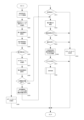
上述したように、本実施例にあって、署名光学コード読取認証装置26は、専用の光学コード読取認証プログラムをインストールしたコンピュータにより実現される。図6は、光学コード読取認証プログラムの処理内容を示すフローチャートである。かかる光学コード読取認証プログラムは、署名光学コード1の読取りと認証を実行する。また、光学コード読取認証プログラムは、読み取ったメッセージがウェブアドレスである場合は、認証成功時に当該ウェブアドレスのサイトにアクセスする処理を実行可能に構成される。なお、図6の各ステップにおいて、本発明に係る画像取得処理は主にステップS11で実現され、本発明に係る読取処理は主にステップS12~S18で実現され、本発明に係る証明書確認処理は主にステップS19で実現され、本発明に係る証明書取得処理は主にステップS20で実現され、本発明に係る検証処理はステップS23で実現され、本発明に係る読取認証結果出力処理は主にステップS25~S28で実現される。
図6の各ステップにおける詳細は下記のとおりである。
S11:コンピュータに内蔵された撮像装置、又はコンピュータに外部接続された撮像装置によって署名光学コード1を撮像し、画像データを取得する。
S12:ステップS11で撮像した画像から署名光学コード1を識別し、さらに、明色モジュール2aと暗色モジュール2bのパターンを識別する。
S13:識別した明色モジュール2aと暗色モジュール2bのパターンから、第1記録領域に記録されたデータを読み取る。
S14:埋め草領域に記録されたデータ(特に、電子署名フラッグの値)を確認する。
S15:電子署名が記録されていない場合はステップS16へ移行し、電子署名が記録されている場合はステップS17へ移行する。
S16:第1記録領域の使用領域に記録されたメッセージを表示画面に表示して、プログラムを終了する。
S17:ステップS11で撮像した画像に基づいてサブモジュールの配色の識別を行う。
S18:ステップS16で識別したサブモジュールの配色等に基づいて、第2記録領域に記録されたデータを読み取る。
S19:署名光学コード1に記録された公開鍵IDに対応する公開鍵証明書を、通信端末に記憶済みであるか否かを判定し、記憶済みである場合には、ステップS23へ移行する。記憶済みでない場合はステップS20へ移行する。
S20:インターネット24を介して証明書提供サーバ23から当該公開鍵IDに対応する公開鍵証明書を取得し、取得した公開鍵証明書の有効性を認証局22に確認する。なお、証明書提供サーバ23のウェブアドレスは、光学コード読取認証プログラムに設定済みのものを用いる。
S21:ステップS20で有効な公開鍵証明書の取得に成功した場合は、ステップS23へ移行する。取得に失敗した場合はステップS22へ移行する。
S22:署名光学コード1の認証に失敗したことを示すメッセージを表示して、プログラムを終了する。
S23: 公開鍵証明書を用いて署名光学コード1に記録された電子署名を検証することにより、署名光学コード1を認証する。かかる認証は公開鍵基盤における常法による。すなわち、ハッシュ関数を用いてメッセージからダイジェストを作成するとともに、取得した公開鍵証明書(公開鍵)を用いて電子署名からダイジェストを復号し、2つのダイジェストの値を比較することにより、当該署名光学コードの作成者が公開鍵証明書の所有者であって、当該署名光学コードに記録されたメッセージが改変されていないことを確認する。
S24:ステップS23の検証結果が正常である場合にはステップS25へ移行し、検証結果が異常である場合はステップS22へ移行する。
S25:署名光学コード1に記録されたメッセージと、公開鍵証明書に記録された作成者の識別情報(氏名、住所等)とを、表示画面に表示する。
S26:メッセージがウェブアドレス(URL)である場合にはステップS27へ移行し、ウェブアドレスでない場合はプログラムを終了する。
S27:検証に使用した公開鍵証明書について、ウェブアクセスの確認不要設定がなされている場合にはステップS31へ移行する。確認不要設定がなされていない場合はステップS28へ移行する。
S28:表示画面に表示したウェブアドレスにアクセスするか否かを確認するアクセス確認画面を表示する。
S29:ステップS28でアクセスが許可されなかった場合はプログラムを終了する。アクセスが許可された場合は、ステップS30へ移行する。
S30:今後、同じ公開鍵証明書で検証した署名光学コード1について、アクセス確認画面を表示するか否かを確認する。
S31:ウェブブラウザを起動させて、署名光学コード1に記録されたウェブアドレスのサイトにアクセスさせる。
As described above, in this embodiment, the signature optical code
Details of each step in FIG. 6 are as follows.
S11: An imaging device built into the computer or an imaging device externally connected to the computer takes an image of the signature
S12: Identify the signature
S13: The data recorded in the first recording area is read from the identified patterns of the
S14: Check the data recorded in the padding area (in particular, the value of the electronic signature flag).
S15: If the electronic signature is not recorded, the process proceeds to step S16, and if the electronic signature is recorded, the process proceeds to step S17.
S16: Display the message recorded in the used area of the first recording area on the display screen, and terminate the program.
S17: Identify the color scheme of the sub-module based on the image captured in step S11.
S18: Read the data recorded in the second recording area based on the sub-module coloration or the like identified in step S16.
S19: Determine whether or not the public key certificate corresponding to the public key ID recorded in the signature
S20: Acquire a public key certificate corresponding to the public key ID from the
S21: If the acquisition of a valid public key certificate is successful in step S20, the process proceeds to step S23. If the acquisition fails, the process proceeds to step S22.
S22: Display a message indicating that the authentication of the signed
S23: Authenticate the signed
S24: When the verification result of step S23 is normal, the process proceeds to step S25, and when the verification result is abnormal, the process proceeds to step S22.
S25: Display the message recorded in the signature
S26: If the message is a web address (URL), go to step S27; otherwise, terminate the program.
S27: If the public key certificate used for verification is set to not require confirmation of web access, the process proceeds to step S31. If no confirmation is set, the process proceeds to step S28.
S28: Display an access confirmation screen for confirming whether or not to access the web address displayed on the display screen.
S29: If access is not permitted in step S28, terminate the program. If access is permitted, the process proceeds to step S30.
S30: Confirm whether or not to display an access confirmation screen for the signed
S31: Launch a web browser to access the site of the web address recorded in the signature
図7,8を用いて、本実施例の光学コード認証システムの具体的な利用例を説明する。
図7(a)は、本実施例の光学コード認証システムを利用した銀行のチラシである。かかるチラシには、○×銀行の広告情報とともに、本実施例に係る署名光学コード1が印刷される。署名光学コード1には、メッセージとして作成者(株式会社○×銀行)のウェブアドレスが記録されるとともに、作成者の秘密鍵を用いて作成した電子署名と、作成者の公開鍵IDが記録される。かかるチラシの署名光学コード1を、本実施例に係る署名光学コード読取認証装置26(スマートフォンなど)で読み取った場合、当該署名光学コード1は正しく認証されて、図7(b)に示すように、署名光学コード読取認証装置26の表示画面に、署名光学コード1に記録されたウェブアドレスと、作成者の識別情報(名称と住所)が表示されるとともに、当該ウェブアドレスにアクセスするか否かの確認画面が表示される。仮に、署名光学コードの作成者が○×銀行以外である場合には、○×銀行以外の名称が作成者として表示されるため、読み手はチラシに印刷された○×銀行の文字と、表示画面に表示された作成者の名称を比較することで、当該署名光学コードが広告主である○×銀行が作成したものであることを確認できる。また、仮に、署名光学コードに記録されたウェブアドレスが改ざんされていた場合には、電子署名の検証に失敗してエラーメッセージが表示されるため、読み手は、当該エラーメッセージが表示されていないことをもって、当該署名光学コードが改ざんされていないものであるとわかる。このように、本実施例の光学コード認証システムを用いれば、ウェブアドレスを記録した光学コードの信頼性を高めることができるため、作成者を偽った光学コードやウェブアドレスを改ざんした光学コードを用いてフィッシングサイトに誘導する行為を好適に防止できる。
A specific example of use of the optical code authentication system of this embodiment will be described with reference to FIGS.
FIG. 7(a) is a leaflet of a bank using the optical code authentication system of this embodiment. The signature
図8(a)は、本実施例の光学コード認証システムを利用した資格認定証である。かかる資格認定証には、文字と数字からなる資格認定情報が印刷されるとともに、本実施例に係る署名光学コード1が印刷される。資格認定情報には、資格の名称、被認定者の個人情報(名前及び生年月日)、資格認定日、資格認定者の名称と代表者が含まれる。一方、署名光学コード1には、メッセージとして、資格認定証に印刷された資格認定情報の一部(資格名、被認定者の氏名、及び資格認定日)が記録されるとともに、資格認定者である作成者(○×検定協会)の秘密鍵を用いて作成した電子署名と、作成者の公開鍵IDが記録される。すなわち、かかる資格認定証の製造方法は、署名光学コード1に記録する資格認定情報と、作成者の秘密鍵に基づいて電子署名を作成するステップと、当該資格認定情報と、電子署名と、作成者の公開鍵IDとを記録する署名光学コード1を作成するステップと、資格認定情報と署名光学コード1とを用紙に印刷するステップとを含む。資格認定情報と署名光学コード1は、同時に印刷してもよいし、別々に印刷してもよい。かかる資格認定証に印刷された署名光学コード1を、本実施例に係る署名光学コード読取認証装置26(スマートフォンなど)で読み取った場合、当該署名光学コード1は正しく認証されて、図8(b)に示すように、署名光学コード読取認証装置26の表示画面に、署名光学コード1に記録された資格名、被認定者の氏名、及び資格認定日が表示されるとともに、公開鍵証明書に記録された作成者の識別情報(名称及び住所)が表示される。このため、読み手は資格認定証に印刷された資格認定情報と、表示画面に表示された情報とを比較することで、当該署名光学コードが資格認定者である○×検定協会が作成したものであることを確認できる。また、仮に、署名光学コードに記録された資格名や被認定者名が改ざんされていた場合は、電子署名の検証に失敗してエラーメッセージが表示されるため、読み手は、当該エラーメッセージが表示されていないことをもって、当該署名光学コードが改ざんされていないものであるとわかる。このように、本実施例の光学コード認証システムを用いれば、資格認定証の印刷情報の信頼性を高めることができるため、各種証書の偽造印刷物の流通を好適に防止できる。なお、本段落では、資格認定証を例に挙げて説明したが、本実施例は、資格認定証に限られず、証書全般の認証に利用可能である。資格認定証以外の証書の具体例としては、公文書、住民票、契約書、領収書、請求書、認証シール、処方箋、郵便物、クレジットカード、有価証券、金券などが挙げられる。なお、有価証券や金券については、有価証券や金券については、偽造防止機能以外にも、複写防止機能が求められる。このため、本実施例を有価証券や金券に適用する場合には、署名光学コードの暗色モジュール2bのサブモジュールを、黒色と青色の2色でなく、赤外光の反射特性の異なる2種類の黒色で配色することが望ましい。かかる構成とすれば、サブモジュールの配色を、汎用の複写機では識別困難となるためである。
FIG. 8(a) is a qualification certificate using the optical code authentication system of this embodiment. Qualification information consisting of letters and numbers is printed on the qualification certificate, and the signature
本実施例は、実施例1の光学コード認証システムを応用した代金決済システムである。このため、実施例1と共通する構成については詳細な説明を省略する。 This embodiment is a payment settlement system to which the optical code authentication system of the first embodiment is applied. Therefore, detailed description of the configuration common to the first embodiment will be omitted.
本実施例の代金決済システムは、決済用情報が記録された決済用光学コードを代金受取者が提示し、代金支払者の決済用端末が当該決済用光学コードを読み取って、代金支払者への支払いを決済代行サーバに要求し、決済代行サーバが代金支払者と代金受け取り者との代金決済を仲介するタイプのシステムである。本実施例では、かかる決済用光学コードに、実施例1に係る署名光学コードを使用する。具体的には、本実施例では、代金受取者が、決済用光学コードの作成者となる。そして、決済用光学コードには、代金受取者の決済用情報をメッセージとして記録するとともに、第1記録領域の埋め草領域に代金受取者の公開鍵IDを、第2記録領域に代金受取者の秘密鍵を用いて当該メッセージから作成した電子署名を記録する。決済用光学コードに記録される代金受取者の決済用情報には、決済用サーバのウェブアドレスと、当該決済用サーバが代金受取者を特定可能な決済用IDとが含まれる。なお、かかる決済用情報には、決済対象の商品やサービスの代金を含ませることもできる。 In the payment system of this embodiment, the payee presents a payment optical code in which payment information is recorded, the payment terminal of the payment payer reads the payment optical code, and sends the payment to the payment payer. This is a type of system in which a payment is requested to a settlement agency server, and the settlement agency server mediates payment settlement between a payer and a payee. In this embodiment, the signature optical code according to the first embodiment is used as the settlement optical code. Specifically, in this embodiment, the payee is the creator of the payment optical code. In the settlement optical code, the payment information of the payee is recorded as a message, the public key ID of the payee is recorded in the padding area of the first recording area, and the payee's public key ID is stored in the second recording area. Record an electronic signature created from the message using the private key. The payment information of the payee recorded in the payment optical code includes the web address of the payment server and a payment ID that allows the payment server to identify the payee. The payment information can also include the price of the product or service to be paid.
本実施例の代金決済システムは、上記決済用光学コードと、決済用光学コードを作成するための決済用光学コード作成装置と、決済用光学コードを読み取り可能な代金支払者の決済用端末と、決済用端末からの要求に応じて代金受取者の公開鍵証明書を提供する証明書提供サーバと、決済用端末からの要求に応じて代金支払者と代金受取者との代金決済を代行する決済用サーバとを備えている。 The payment system of this embodiment comprises the optical payment code, an optical payment code creation device for creating the optical payment code, a payment terminal capable of reading the optical payment code, and a payment terminal. A certificate providing server that provides the public key certificate of the payee in response to a request from a payment terminal, and a settlement that performs payment settlement between the payer and the payee in response to a request from the payment terminal. with a server for
証明書提供サーバは、実施例1に係る証明書提供サーバと同じものである。また、決済用光学コードは、実施例1に係る署名光学コードであるから、決済用光学コード作成装置は、実施例1に係る署名光学コード作成装置、すなわち、光学コード作成プログラムをインストールしたコンピュータにより実現される。代金支払者の決済用端末は、専用の決済用プログラムをインストールし、代金支払者の決済用情報を記憶させたコンピュータにより実現される。具体的には、スマートフォンなどの通信機能と撮像機能を有する通信端末が決済用端末として好適である。決済用プログラムの詳細は後述する。代金支払者の決済用情報には、決済代行事業者が代金支払者を特定可能な決済用IDが含まれる。決済用サーバは、決済代行事業者が運営する既存のサーバにより実現される。なお、本実施例の代金決済システムは、複数の決済代行事業者を利用した決済を可能としている。 The certificate providing server is the same as the certificate providing server according to the first embodiment. Further, since the optical code for settlement is the signature optical code according to the first embodiment, the optical code for settlement is created by the signature optical code creation device according to the first embodiment, i.e., a computer in which the optical code creation program is installed. Realized. The settlement terminal of the payer is implemented by a computer in which a dedicated settlement program is installed and settlement information of the payer is stored. Specifically, a communication terminal having a communication function and an imaging function, such as a smart phone, is suitable as a payment terminal. Details of the settlement program will be described later. The payment information of the payer includes a payment ID that allows the payment agent to identify the payer. The settlement server is implemented by an existing server operated by a settlement agent. The payment settlement system of this embodiment enables settlement using a plurality of settlement service providers.
本実施例の代金決済システムでは、まず、実施例1と同様にして(図4参照)、代金受取者(作成者)が、決済用光学コードの作成に先立って、決済用光学コード作成装置に、自己の秘密鍵と公開鍵IDを記憶させる。すなわち、自己の公開鍵証明書と秘密鍵を認証局から取得するととともに、自己の公開鍵証明書の登録を証明書提供サーバに要求し、証明書提供サーバから自己の公開鍵IDを取得する。 In the payment system of this embodiment, first, as in the first embodiment (see FIG. 4), the payee (creator) uses the payment optical code creation device prior to creating the payment optical code. , stores its own private key and public key ID. That is, it obtains its own public key certificate and private key from the certification authority, requests the certificate providing server to register its own public key certificate, and obtains its own public key ID from the certificate providing server.
続いて、代金受取者は、決済用光学コードに記録する決済用情報を取得する。すなわち、決済代行事業者に、自己の個人情報(氏名、住所、銀行口座など)を伝えて決済代行を依頼し、決済代行事業者から決済用サーバのウェブアドレスと、自己の決済用IDを取得する。なお、認証局や証明書提供サーバの運営事業者が、決済代行事業者と同じである場合には、決済用情報の取得手続きを、秘密鍵や公開鍵IDの取得手続きと一括して行うことができる。 Subsequently, the payee acquires payment information to be recorded in the payment optical code. In other words, tell the payment agent your personal information (name, address, bank account, etc.) and request the payment agent, and obtain the web address of the payment server and your ID for payment from the payment agent. do. If the operator of the certificate authority or certificate providing server is the same as the payment service provider, the procedure for obtaining payment information must be performed together with the procedure for obtaining a private key or public key ID. can be done.
代金受取者は、取得した決済用情報を記録した決済用光学コードを決済用光学コード作成装置により作成し、当該決済用光学コードを印刷した印刷物を、店舗の代金支払場所に提示する。そして、当該店舗の利用者は(代金支払者)は、代金の支払時に、店舗に提示された決済用光学コードを自己の決済用端末に読み取らせて、決済用サーバに代金支払いの仲介を要求する。ここで、本実施例では、決済用端末は、決済用サーバにアクセスするのに先立って、使用者(代金支払者)に対して代金受取者の確認を要求する。具体的には、実施例1と同様にして、決済用光学コードに記録された電子署名を検証し、検証結果が正常であった場合には、代金受取者(作成者)の公開鍵証明書に記録された代金受取者の識別情報を表示画面に表示するとともに、当該代金受取者へ代金を支払うか否かの確認画面を表示する。 The payee creates a payment optical code recording the acquired payment information by using a payment optical code creation device, and presents a printed matter on which the payment optical code is printed at the payment place of the store. Then, the user of the store (payer), when paying the price, has his/her payment terminal read the optical code for payment presented to the store, and requests the payment server to mediate the payment. do. Here, in this embodiment, the settlement terminal requests confirmation of the payee from the user (payer) before accessing the settlement server. Specifically, in the same manner as in Example 1, the electronic signature recorded in the payment optical code is verified, and if the verification result is normal, the public key certificate of the payee (creator) The identification information of the payee recorded in the display screen is displayed, and a confirmation screen is displayed as to whether or not to pay the payee to the payee.
図9は、決済用端末にインストールされる決済用プログラムの処理内容を示すフローチャートである。
なお、図9の各ステップにおいて、本発明に係る公開鍵取得手段は主にステップS50で実現され、本発明に係る認証手段は主にステップS53で実現され、本発明に係る受取者情報表示手段は主に
本発明に係る決済要求手段は主に
図9の各ステップにおける詳細は下記のとおりである。
S41:決済用端末に内蔵された撮像装置、又は通信端末に外部接続された撮像装置によって決済用光学コードを撮像する。
S42:ステップS41で撮像した画像から決済用光学コードを識別し、さらに、明色モジュール2aと暗色モジュール2bのパターンを識別する。
S43:識別した明色モジュール2aと暗色モジュール2bのパターンから、第1記録領域に記録されたデータを読み取る。
S44:埋め草領域に記録されたデータ(特に、電子署名フラッグの値)を確認する。
S45:電子署名が記録されていない場合はステップS46へ移行し、電子署名が記録されている場合はステップS47へ移行する。
S46:決済用光学コードの認証に失敗したことを示すメッセージを表示して、プログラムを終了する。
S47:ステップS41で撮像した画像に基づいてサブモジュールの配色の識別を行う。
S48:ステップS46で識別したサブモジュールの配色等に基づいて、第2記録領域に記録されたデータを読み取る。
S49:決済用光学コードに記録された公開鍵IDに対応する公開鍵証明書を、通信端末に記憶済みである場合には、ステップS53へ移行する。記憶済みでない場合はステップS50へ移行する。
S50:インターネットを介して証明書提供サーバから当該公開鍵IDに対応する公開鍵証明書を取得し、取得した公開鍵証明書の有効性を認証局に確認する。なお、証明書提供サーバのウェブアドレスは、決済用プログラムに設定済みのものを用いる。
S51:ステップS50で有効な公開鍵証明書の取得に成功した場合は、ステップS53へ移行する。取得に失敗した場合は、ステップS52へ移行する。
S52:決済用光学コードの認証に失敗したことを示すメッセージを表示して、プログラムを終了する。
S53:公開鍵証明書を用いて決済用光学コードに記録された電子署名を検証することにより、決済用光学コードを認証する。かかる認証は公開鍵基盤における常法による。すなわち、ハッシュ関数を用いてメッセージからダイジェストを作成するとともに、取得した公開鍵証明書(公開鍵)を用いて電子署名からダイジェストを復号し、2つのダイジェストの値を比較することにより、当該決済用光学コードの作成者が公開鍵証明書の所有者であって、当該決済用コードに記録された代金受取者の識別情報が改変されていないことを確認する。
S54:ステップS54の検証結果が正常である場合にはステップS55へ移行し、検証結果が異常である場合はステップS52へ移行する。
S55:メッセージが決済用情報の書式を満たしている場合は、ステップS56へ移行し、決済用情報の書式を満たしていない場合は、ステップS52へ移行する。
S56:決済端末の表示画面に、代金決済用サーバへのアクセスをユーザーに確認するアクセス確認画面を表示する。図10に示すように、アクセス確認画面では、決済代行事業者、決済サーバ、代金受取者の氏名及び住所が表示されるとともに、決済用サーバへのアクセス可否を確認するメッセージが表示される。決済サーバは、決済用光学コードに記録された決済用情報に含まれるものである。決済代行事業者名は、決済用プログラムが決済サーバのアドレスと紐付けして予め記憶するものであり、決済代行事業者名を記憶していない場合は、「不明」と表示される。代金受取者の氏名及び住所は、公開鍵証明書に所有者情報として記録されたものが表示される。このように、本実施例の代金決済システムでは、決済用端末で決済用サーバにアクセスする前に、代金支払者が、決済代行事業者や代金受取者を確認することができる。
S57:ステップS56でユーザーがアクセスを許可しなかった場合は、プログラムを終了する。アクセスを検証した場合には、ステップS58へ移行する。
S58:決済処理を行う。すなわち、決済用光学コードに記録された決済用サーバに代金支払者と代金受取者の決済用IDと支払い金額を送信して、代金受取者への支払いを要求する。決済用サーバとの決済処理は常法に則って行うことができる。
FIG. 9 is a flow chart showing the processing contents of the payment program installed in the payment terminal.
In each step of FIG. 9, the public key obtaining means according to the present invention is mainly realized at step S50, the authentication means according to the present invention is mainly realized at step S53, and the recipient information display means according to the present invention. The details of each step in FIG. 9 are mainly as follows for the settlement request means according to the present invention.
S41: An imaging device built into the payment terminal or an imaging device externally connected to the communication terminal captures an image of the payment optical code.
S42: The optical code for payment is identified from the image captured in step S41, and the patterns of the
S43: The data recorded in the first recording area is read from the identified patterns of the light-
S44: Check the data recorded in the padding area (in particular, the value of the electronic signature flag).
S45: If the electronic signature is not recorded, the process proceeds to step S46, and if the electronic signature is recorded, the process proceeds to step S47.
S46: Display a message indicating that the authentication of the optical code for payment has failed, and terminate the program.
S47: Based on the image captured in step S41, the color scheme of the sub-module is identified.
S48: Read the data recorded in the second recording area based on the sub-module coloration or the like identified in step S46.
S49: If the public key certificate corresponding to the public key ID recorded in the payment optical code has already been stored in the communication terminal, the process proceeds to step S53. If it has not been stored, the process proceeds to step S50.
S50: Acquire a public key certificate corresponding to the public key ID from the certificate providing server via the Internet, and confirm validity of the acquired public key certificate with the certificate authority. The web address of the certificate providing server is already set in the settlement program.
S51: If the acquisition of a valid public key certificate is successful in step S50, the process proceeds to step S53. If the acquisition fails, the process proceeds to step S52.
S52: Display a message indicating that the authentication of the optical code for payment has failed, and terminate the program.
S53: The optical code for payment is authenticated by verifying the electronic signature recorded in the optical code for payment using the public key certificate. Such authentication is conventional in public key infrastructure. In other words, a hash function is used to create a digest from the message, the obtained public key certificate (public key) is used to decrypt the digest from the electronic signature, and the two digest values are compared to determine the Confirm that the creator of the optical code is the owner of the public key certificate and that the identification information of the payee recorded in the payment code has not been altered.
S54: When the verification result of step S54 is normal, the process proceeds to step S55, and when the verification result is abnormal, the process proceeds to step S52.
S55: If the message satisfies the format of the payment information, proceed to step S56. If not, proceed to step S52.
S56: An access confirmation screen is displayed on the display screen of the payment terminal for confirming access to the payment server for the user. As shown in FIG. 10, the access confirmation screen displays the name and address of the settlement agency, the settlement server, and the payee, as well as a message for confirming whether or not access to the settlement server is permitted. The settlement server is included in the settlement information recorded in the settlement optical code. The name of the settlement agency is stored in advance by the settlement program in association with the address of the settlement server. If the name of the settlement agency is not stored, "unknown" is displayed. The name and address of the payee are displayed as owner information recorded in the public key certificate. As described above, in the payment system of this embodiment, the payment person can confirm the payment service provider and the payment recipient before accessing the payment server with the payment terminal.
S57: If the user does not permit access in step S56, terminate the program. If the access is verified, the process moves to step S58.
S58: Perform settlement processing. That is, the payment IDs of the payer and the payee and the payment amount are transmitted to the payment server recorded in the payment optical code, and payment is requested to the payee. Settlement processing with the settlement server can be performed in accordance with ordinary methods.
以上のように、本実施例の代金決済システムでは、代金支払者が決済用端末で代金決済サーバにアクセスする前に、決済用光学コードの作成者(代金受取者)の識別情報を確認することができるため、従来の代金決済システムよりも安全に代金の授受を行うことが可能となる。また、本実施例の代金決済システムに係る決済用プログラムは、複数の決済代行事業者に対応可能であるから、代金支払者は、決済代行事業者ごとに決済用プログラムを選択して起動させる手間を省くことができる。 As described above, in the payment system of this embodiment, the identification information of the creator of the optical code for payment (payee) can be confirmed before the payer accesses the payment server using the payment terminal. Therefore, payment can be made more safely than the conventional payment system. In addition, since the payment program related to the payment system of the present embodiment can be applied to a plurality of payment service providers, the payment payer does not have to worry about selecting and starting the payment program for each payment service provider. can be omitted.
なお、本発明は、上記実施例の構成に限定されず、本発明の趣旨を逸脱しない範囲で、上記実施例の構成を種々変更することができる。例えば、上記実施例では、署名光学コードがQRコードと互換性を有しているが、本発明に係る署名光学コードは、QRコード以外の規格の光学コードと互換性を有するものであってもよいし、既存の規格と互換性のないものであってもよい。 It should be noted that the present invention is not limited to the configurations of the above embodiments, and various modifications can be made to the configurations of the above embodiments without departing from the scope of the present invention. For example, in the above embodiment, the signature optical code is compatible with the QR code, but the signature optical code according to the present invention may be compatible with standard optical codes other than the QR code. and may be incompatible with existing standards.
また、上記実施例に係る署名光学コードは、第1記録領域にメッセージと公開鍵IDを記録し、第2記録領域に電子署名を記録しているが、本発明に係る署名光学コードにあって、メッセージや公開鍵ID、電子署名を記録する領域は特に限定されない。また、本発明に係る署名光学コードは、拡張領域(第2記録領域)を具備するものに限られない。 In the signature optical code according to the above embodiment, the message and public key ID are recorded in the first recording area, and the electronic signature is recorded in the second recording area. , a message, a public key ID, and an electronic signature are not particularly limited. Also, the signature optical code according to the present invention is not limited to one having an extension area (second recording area).
また、上記実施例の光学コード認証システムや代金決済システムは、公開鍵基盤における認証局を利用しているが、本発明に係る秘密鍵や公開鍵、公開鍵証明書は、認証局が発行したものに限らず、署名光学コードの作成者自らが作成したものであってもよい。 Further, the optical code authentication system and the payment system of the above embodiments use a certificate authority in the public key infrastructure. The signature optical code may be created by the creator of the signed optical code.
また、上記実施例の光学コード認証システムでは、証明書提供サーバのウェブアドレスが、光学コード読取認証プログラムに予め設定されており、当該ウェブアドレスの証明書提供サーバに、公開鍵証明書を要求するよう構成されているが、かかる構成に替えて、公開鍵証明書を提供する証明書提供サーバを特定可能な情報を、署名光学コードに記録してもよい。なお、かかる情報は、当該公開鍵IDに含めてもよいし、公開鍵IDとは別に署名光学コードに記録してもよい。 Further, in the optical code authentication system of the above embodiment, the web address of the certificate providing server is preset in the optical code reading authentication program, and the public key certificate is requested from the certificate providing server of the web address. However, instead of such a configuration, information that can identify the certificate providing server that provides the public key certificate may be recorded in the signature optical code. Such information may be included in the public key ID, or may be recorded in the signature optical code separately from the public key ID.
また、上記実施例1では、署名光学コード読取認証装置26が、署名光学コード1の読取りと認証を実行するが、署名光学コード読取認証装置26の機能を、読取装置と認証装置の2つの機器で実現する構成としてもよい。すなわち、かかる構成では、読取装置が署名光学コード1を読み取って、署名光学コード1に記録されたデータ(メッセージ、電子署名、及び公開鍵ID)を認証装置へ出力し、認証装置が、当該出力データに基づいて署名光学コード1の認証を行い、認証結果を出力することとなる。
In the first embodiment, the signature optical code reading/
1 署名光学コード
2a 明色モジュール
2b 暗色モジュール
3 サブモジュール
20 作成者
21 署名光学コード作成装置
22 認証局
23 証明書提供サーバ
24 インターネット
25 読み手
26 署名光学コード読取認証装置
1 signature
Claims (7)
前記メッセージと、
前記電子署名と、
前記秘密鍵と対をなす公開鍵を含む前記作成者の公開鍵証明書を特定可能であって、前記公開鍵証明書よりもサイズの小さい公開鍵IDと
を記録した光学コードを作成する光学コード作成処理と
をコンピュータに実行させるための光学コード作成プログラムであって、
前記光学コードは、明色と識別される明色モジュールと、暗色と識別される暗色モジュールとを備え、
前記明色モジュールと前記暗色モジュールの少なくとも一部は、複数種類の光反射特性を具備することにより、及び/又は、微細な領域に細分化されることにより、2ビット以上を記憶可能な多値化モジュールであり、
前記光学コードは、前記明色モジュールと前記暗色モジュールのパターンでデータを記録する第1記録領域と、前記多値化モジュールのパターンでデータを記録する第2記録領域とを含み、
前記光学コード作成処理では、
前記電子署名を前記第2記録領域に記録し、
前記電子署名が前記第2記録領域に記録されていることを示す指標と、前記メッセージとを前記第1記録領域に記録することを特徴とする光学コード作成プログラム。 an electronic signature creation process for creating an electronic signature from the message using the private key of the creator of the optical code;
said message;
the electronic signature;
An optical code for creating an optical code that can specify a public key certificate of the creator that includes a public key paired with the private key and records a public key ID that is smaller in size than the public key certificate. An optical code creation program for causing a computer to execute a creation process,
the optical code comprises a light module identified as light and a dark module identified as dark;
At least a part of the light-color module and the dark-color module have multiple types of light reflection characteristics and/or are subdivided into fine areas, so that they are multi-valued capable of storing two or more bits. module,
The optical code includes a first recording area for recording data in a pattern of the light module and the dark module, and a second recording area for recording data in a pattern of the multi-value module,
In the optical code creation process,
record the electronic signature in the second recording area;
An optical code creation program for recording an index indicating that the electronic signature is recorded in the second recording area and the message in the first recording area.
前記複数のサブモジュールは、光反射特性の異なる複数種類の暗色のいずれかに配色されており、
前記第2記録領域は、前記サブモジュールの配色パターンによってデータを記録するものであることを特徴とする請求項1に記載の光学コード作成プログラム。 the dark module is subdivided into a plurality of sub-modules,
The plurality of sub-modules are colored in one of a plurality of types of dark colors having different light reflection characteristics,
2. The optical code creation program according to claim 1 , wherein the second recording area records data according to the color pattern of the sub-module.
前記第2記録領域は、前記変動領域に含まれる前記暗色モジュールの前記サブモジュールの配色パターンによってデータを記録する変動第2記録領域と、前記固定領域に含まれる前記暗色モジュールの前記サブモジュールの配色パターンによってデータを記録する固定第2記録領域とを有し、
前記光学コード作成処理では、
前記変動第2記録領域と前記固定第2記録領域の夫々に、データと、当該データの誤り訂正データを記録し、
前記第1記録領域の、前記メッセージを記録しない領域に、前記変動第2記録領域と前記固定第2記録領域の夫々に記録したデータと誤り訂正データのサイズを記録することを特徴とする請求項2に記載の光学コード作成プログラム。 In the optical code, a variable area in which a pattern of light modules and dark modules varies according to data to be recorded in the first recording area, and a pattern of light modules and dark modules are determined in advance, and can be optically read. and a fixed region that constitutes an assisting pattern,
The second recording area includes a variable second recording area for recording data according to a color scheme pattern of the sub-module of the dark module included in the variable area, and a color scheme of the sub-module of the dark module included in the fixed area. a fixed second recording area for recording data according to a pattern;
In the optical code creation process,
recording data and error correction data for the data in each of the variable second recording area and the fixed second recording area;
3. The sizes of the data recorded in the variable second recording area and the size of the error correction data respectively recorded in the variable second recording area and the fixed second recording area are recorded in areas of the first recording area in which the message is not recorded. 3. The optical code creation program according to 2 .
前記光学コード作成処理では、
前記変動第2記録領域と前記固定第2記録領域の夫々に記録可能な誤り訂正データのサイズに応じて、訂正能力が最大となるように、夫々に記録する誤り訂正データのサイズを決定することを特徴とする請求項3に記載の光学コード作成プログラム。 The error correction data is a Reed-Solomon code,
In the optical code creation process,
Determining the size of the error correction data to be recorded in each of the variable second recording area and the fixed second recording area according to the size of the error correction data recordable in each of the variable second recording area and the fixed second recording area so as to maximize the correction capability. The optical code creation program according to claim 3 , characterized by:
前記コンピュータに内蔵又は接続された撮像装置が撮像した前記光学コードの画像データを取得する画像取得処理と、
前記画像取得処理で取得した前記画像データに基づいて、前記光学コードに記録された前記メッセージと、前記電子署名と、前記公開鍵IDとを読み取る読取処理と、
前記読取処理で読み取った前記公開鍵IDに基づいて、通信回線を介して所定の証明書提供サーバから前記公開鍵証明書を取得する証明書取得処理と、
前記光学コードに記録された前記電子署名を、当該光学コードに記録された前記公開鍵IDに対応する前記公開鍵証明書に基づいて検証する検証処理と、
前記検証処理で前記電子署名が正常であると判定した場合に、前記メッセージと、前記公開鍵証明書に含まれる前記作成者の識別情報とを出力する読取認証結果出力処理と
を前記コンピュータに実行させるための光学コード読取認証プログラムであり、
前記光学コードは、
明色と識別される明色モジュールと、暗色と識別される暗色モジュールとを備え、
前記明色モジュールと前記暗色モジュールの少なくとも一部が、複数種類の光反射特性を具備することにより、及び/又は、微細な領域に細分化されることにより、2ビット以上を記憶可能な多値化モジュールであり、
前記明色モジュールと前記暗色モジュールのパターンでデータを記録する第1記録領域と、前記多値化モジュールのパターンでデータを記録する第2記録領域とを含み、
前記電子署名が前記第2記録領域に記録され、前記電子署名が前記第2記録領域に記録されていることを示す指標と、前記メッセージとが前記第1記録領域に記録されたものであり、
前記読取処理では、前記第1記録領域の記録データを読み取って、読み取ったデータに前記指標が含まれている場合に、前記第2記録領域のデータを読み取ることを特徴とする光学コード読取認証プログラム。 A public key ID capable of identifying a message, a digital signature created from the message using a private key of the creator of the optical code, and a public key certificate of the creator including a public key paired with the private key A program for causing a computer to read an optical code recorded with
An image acquisition process for acquiring image data of the optical code captured by an imaging device built in or connected to the computer;
reading processing for reading the message recorded in the optical code, the electronic signature, and the public key ID based on the image data acquired in the image acquisition processing;
certificate acquisition processing for acquiring the public key certificate from a predetermined certificate providing server via a communication line based on the public key ID read in the reading processing;
a verification process of verifying the electronic signature recorded in the optical code based on the public key certificate corresponding to the public key ID recorded in the optical code;
If the verification process determines that the electronic signature is normal, read authentication result output processing for outputting the message and the identification information of the creator included in the public key certificate is executed on the computer. is an optical code reading authentication program for
The optical code is
A light module identified as light and a dark module identified as dark,
At least a part of the light-color module and the dark-color module has multiple types of light reflection characteristics and/or is subdivided into fine areas, so that 2 or more bits can be stored. module,
a first recording area for recording data with the pattern of the light module and the dark module; and a second recording area for recording data with the pattern of the multi-value module,
wherein the electronic signature is recorded in the second recording area, an indicator indicating that the electronic signature is recorded in the second recording area, and the message are recorded in the first recording area;
The optical code reading authentication program, wherein in the reading process, the data recorded in the first recording area is read, and if the read data contains the index, the data in the second recording area is read. .
前記コンピュータに内蔵又は接続された撮像装置が撮像した前記光学コードの画像データを取得する画像取得処理と、
前記画像取得処理で取得した前記画像データに基づいて、前記光学コードに記録された前記メッセージと、前記電子署名と、前記公開鍵IDとを読み取る読取処理と、
前記読取処理で読み取った前記公開鍵IDに対応する前記公開鍵証明書が、前記コンピュータの記憶装置に記憶されているか否かを判定する証明書確認処理と、
前記光学コードに記録された前記電子署名を、当該光学コードに記録された前記公開鍵IDに対応する前記公開鍵証明書に基づいて検証する検証処理と、
前記検証処理で前記電子署名が正常であると判定した場合に、前記メッセージと、前記公開鍵証明書に含まれる前記作成者の識別情報とを出力する読取認証結果出力処理と
を前記コンピュータに実行させるための光学コード読取認証プログラムであり、
前記光学コードは、
明色と識別される明色モジュールと、暗色と識別される暗色モジュールとを備え、
前記明色モジュールと前記暗色モジュールの少なくとも一部が、複数種類の光反射特性を具備することにより、及び/又は、微細な領域に細分化されることにより、2ビット以上を記憶可能な多値化モジュールであり、
前記明色モジュールと前記暗色モジュールのパターンでデータを記録する第1記録領域と、前記多値化モジュールのパターンでデータを記録する第2記録領域とを含み、
前記電子署名が前記第2記録領域に記録され、前記電子署名が前記第2記録領域に記録されていることを示す指標と、前記メッセージとが前記第1記録領域に記録されたものであり、
前記読取処理では、前記第1記録領域の記録データを読み取って、読み取ったデータに前記指標が含まれている場合に、前記第2記録領域のデータを読み取ることを特徴とする光学コード読取認証プログラム。 A public key ID capable of identifying a message, a digital signature created from the message using a private key of the creator of the optical code, and a public key certificate of the creator including a public key paired with the private key A program for causing a computer to read an optical code recorded with
An image acquisition process for acquiring image data of the optical code captured by an imaging device built in or connected to the computer;
reading processing for reading the message recorded in the optical code, the electronic signature, and the public key ID based on the image data acquired in the image acquisition processing;
certificate confirmation processing for determining whether or not the public key certificate corresponding to the public key ID read in the reading processing is stored in a storage device of the computer;
a verification process of verifying the electronic signature recorded in the optical code based on the public key certificate corresponding to the public key ID recorded in the optical code;
If the verification process determines that the electronic signature is normal, read authentication result output processing for outputting the message and the identification information of the creator included in the public key certificate is executed on the computer. is an optical code reading authentication program for
The optical code is
A light module identified as light and a dark module identified as dark,
At least a part of the light-color module and the dark-color module has multiple types of light reflection characteristics and/or is subdivided into fine areas, so that 2 or more bits can be stored. module,
a first recording area for recording data with the pattern of the light module and the dark module; and a second recording area for recording data with the pattern of the multi-value module,
wherein the electronic signature is recorded in the second recording area, an indicator indicating that the electronic signature is recorded in the second recording area, and the message are recorded in the first recording area;
The optical code reading authentication program, wherein in the reading process, the data recorded in the first recording area is read, and if the read data contains the index, the data in the second recording area is read. .
請求項5又は請求項6に記載の光学コード読取認証プログラムがインストールされたコンピュータと、
前記公開鍵証明書を前記公開鍵IDと紐付けて記憶するとともに、外部のコンピュータからの要求に応じて、当該要求に含まれる前記公開鍵IDに対応する前記公開鍵証明書を当該コンピュータに通信回線を介して送信する証明書提供サーバと
を備えることを特徴とする光学コード認証システム。 A computer in which the optical code creation program according to any one of claims 1 to 4 is installed;
A computer in which the optical code reading authentication program according to claim 5 or claim 6 is installed;
The public key certificate is stored in association with the public key ID, and in response to a request from an external computer, the public key certificate corresponding to the public key ID included in the request is communicated to the computer. An optical code authentication system, comprising: a certificate providing server for transmission via a line.
Priority Applications (3)
| Application Number | Priority Date | Filing Date | Title |
|---|---|---|---|
| JP2019035464A JP7274202B2 (en) | 2019-02-28 | 2019-02-28 | Optical code creation program, optical code reading authentication program, optical code authentication system, payment system, printed matter manufacturing method, and optical code authentication method |
| PCT/JP2020/007808 WO2020175571A1 (en) | 2019-02-28 | 2020-02-26 | Optical code creation program, optical code readout authentication program, optical code authentication system, payment system, printed article production method, and optical code authentication method |
| US17/459,692 US20220038293A1 (en) | 2019-02-28 | 2021-08-27 | Optical code creation program, optical code reading authentication program, optical code authentication system, payment system, printed article production method, and optical code authentication method |
Applications Claiming Priority (1)
| Application Number | Priority Date | Filing Date | Title |
|---|---|---|---|
| JP2019035464A JP7274202B2 (en) | 2019-02-28 | 2019-02-28 | Optical code creation program, optical code reading authentication program, optical code authentication system, payment system, printed matter manufacturing method, and optical code authentication method |
Publications (2)
| Publication Number | Publication Date |
|---|---|
| JP2020141260A JP2020141260A (en) | 2020-09-03 |
| JP7274202B2 true JP7274202B2 (en) | 2023-05-16 |
Family
ID=72238358
Family Applications (1)
| Application Number | Title | Priority Date | Filing Date |
|---|---|---|---|
| JP2019035464A Active JP7274202B2 (en) | 2019-02-28 | 2019-02-28 | Optical code creation program, optical code reading authentication program, optical code authentication system, payment system, printed matter manufacturing method, and optical code authentication method |
Country Status (3)
| Country | Link |
|---|---|
| US (1) | US20220038293A1 (en) |
| JP (1) | JP7274202B2 (en) |
| WO (1) | WO2020175571A1 (en) |
Citations (7)
| Publication number | Priority date | Publication date | Assignee | Title |
|---|---|---|---|---|
| JP2008090596A (en) | 2006-10-02 | 2008-04-17 | Seiko Instruments Inc | Electronic register, receipt determination device, processing method of electronic register, and receipt determination method |
| JP2009169878A (en) | 2008-01-21 | 2009-07-30 | Hitachi Ltd | Methods for generating, printing and verifying documents constituting group |
| JP2010026608A (en) | 2008-07-15 | 2010-02-04 | Ntt Data Corp | Continuous card payment registration system and computer program |
| US20120308003A1 (en) | 2011-05-31 | 2012-12-06 | Verisign, Inc. | Authentic barcodes using digital signatures |
| JP2015213288A (en) | 2014-04-14 | 2015-11-26 | 株式会社テララコード研究所 | Optical code, information transmission method, and authentication method |
| JP2016201061A (en) | 2015-04-14 | 2016-12-01 | 株式会社テララコード研究所 | Two-dimensional code, and reading method for two-dimensional code |
| JP2018097840A (en) | 2015-12-17 | 2018-06-21 | 株式会社テララコード研究所 | Optical code, printer of optical code, register, and method for printing optical code |
Family Cites Families (2)
| Publication number | Priority date | Publication date | Assignee | Title |
|---|---|---|---|---|
| US20150066765A1 (en) * | 2012-03-30 | 2015-03-05 | Ip Payovation Pty Ltd | Payment apparatus and method |
| US10547458B2 (en) * | 2018-02-06 | 2020-01-28 | Adobe Inc. | Managing and negotiating certificates |
-
2019
- 2019-02-28 JP JP2019035464A patent/JP7274202B2/en active Active
-
2020
- 2020-02-26 WO PCT/JP2020/007808 patent/WO2020175571A1/en active Application Filing
-
2021
- 2021-08-27 US US17/459,692 patent/US20220038293A1/en active Pending
Patent Citations (7)
| Publication number | Priority date | Publication date | Assignee | Title |
|---|---|---|---|---|
| JP2008090596A (en) | 2006-10-02 | 2008-04-17 | Seiko Instruments Inc | Electronic register, receipt determination device, processing method of electronic register, and receipt determination method |
| JP2009169878A (en) | 2008-01-21 | 2009-07-30 | Hitachi Ltd | Methods for generating, printing and verifying documents constituting group |
| JP2010026608A (en) | 2008-07-15 | 2010-02-04 | Ntt Data Corp | Continuous card payment registration system and computer program |
| US20120308003A1 (en) | 2011-05-31 | 2012-12-06 | Verisign, Inc. | Authentic barcodes using digital signatures |
| JP2015213288A (en) | 2014-04-14 | 2015-11-26 | 株式会社テララコード研究所 | Optical code, information transmission method, and authentication method |
| JP2016201061A (en) | 2015-04-14 | 2016-12-01 | 株式会社テララコード研究所 | Two-dimensional code, and reading method for two-dimensional code |
| JP2018097840A (en) | 2015-12-17 | 2018-06-21 | 株式会社テララコード研究所 | Optical code, printer of optical code, register, and method for printing optical code |
Non-Patent Citations (1)
| Title |
|---|
| 寺浦 信之,高密度二次元コードのブロック誤りとランダム誤りに対応する二重誤り訂正システムの検討,FIT2015 第14回情報科学技術フォーラム 講演論文集 第3分冊 査読付き論文・一般論文 画像認,2015年08月24日,pp.571-578 |
Also Published As
| Publication number | Publication date |
|---|---|
| US20220038293A1 (en) | 2022-02-03 |
| WO2020175571A1 (en) | 2020-09-03 |
| JP2020141260A (en) | 2020-09-03 |
Similar Documents
| Publication | Publication Date | Title |
|---|---|---|
| US20200279275A1 (en) | Method for authenticating financial instruments and financial transaction requests | |
| US8626666B2 (en) | Confirming physical custody of objects | |
| US7742996B1 (en) | Computer program, system and method for on-line issuing and verifying a representation of economic value interchangeable for money having identification data and password protection over a computer network | |
| US20080249951A1 (en) | Security systems and methods for digital payments | |
| JP4323098B2 (en) | A signature system that verifies the validity of user signature information | |
| US20190347888A1 (en) | Document authentication system | |
| US20090261158A1 (en) | Authentication of cheques and the like | |
| US20120308003A1 (en) | Authentic barcodes using digital signatures | |
| US20020095383A1 (en) | Method and apparatus for secure sale of electronic tickets | |
| MX2013007923A (en) | High value document authentication system & method. | |
| EA003620B1 (en) | System and method for electronic transmission, storage and retrieval of authenticated documents | |
| US20080255990A1 (en) | On-Line Generation and Verification of Personalised Money | |
| EP2697785A1 (en) | Authentic barcodes using digital signatures | |
| KR101711697B1 (en) | Security bankbook, method and apparatus for providing bankbook printing service using identification code | |
| KR101114542B1 (en) | Discrimination method and apparatus for forgery of wertpapier, and Recording medium thereof | |
| JP7274202B2 (en) | Optical code creation program, optical code reading authentication program, optical code authentication system, payment system, printed matter manufacturing method, and optical code authentication method | |
| JP4800825B2 (en) | Encryption communication method | |
| WO2020031245A1 (en) | Authentication object issuing device, authentication object issuing system, authentication object issuing method, and program | |
| KR101298224B1 (en) | Authentication method using 2-dimensional code | |
| JP2011135275A (en) | Certificate issuance device, certificate authority system, and mobile terminal |
Legal Events
| Date | Code | Title | Description |
|---|---|---|---|
| A621 | Written request for application examination |
Free format text: JAPANESE INTERMEDIATE CODE: A621 Effective date: 20220216 |
|
| A131 | Notification of reasons for refusal |
Free format text: JAPANESE INTERMEDIATE CODE: A131 Effective date: 20230131 |
|
| A521 | Request for written amendment filed |
Free format text: JAPANESE INTERMEDIATE CODE: A523 Effective date: 20230328 |
|
| TRDD | Decision of grant or rejection written | ||
| A01 | Written decision to grant a patent or to grant a registration (utility model) |
Free format text: JAPANESE INTERMEDIATE CODE: A01 Effective date: 20230411 |
|
| A61 | First payment of annual fees (during grant procedure) |
Free format text: JAPANESE INTERMEDIATE CODE: A61 Effective date: 20230424 |
|
| R150 | Certificate of patent or registration of utility model |
Ref document number: 7274202 Country of ref document: JP Free format text: JAPANESE INTERMEDIATE CODE: R150 |