EP0672830B1 - Schlauchfixierungsvorrichtung für Rollenpumpen - Google Patents
Schlauchfixierungsvorrichtung für Rollenpumpen Download PDFInfo
- Publication number
- EP0672830B1 EP0672830B1 EP94102333A EP94102333A EP0672830B1 EP 0672830 B1 EP0672830 B1 EP 0672830B1 EP 94102333 A EP94102333 A EP 94102333A EP 94102333 A EP94102333 A EP 94102333A EP 0672830 B1 EP0672830 B1 EP 0672830B1
- Authority
- EP
- European Patent Office
- Prior art keywords
- hose
- fixing device
- pump
- hose fixing
- receiving means
- Prior art date
- Legal status (The legal status is an assumption and is not a legal conclusion. Google has not performed a legal analysis and makes no representation as to the accuracy of the status listed.)
- Expired - Lifetime
Links
- 239000000463 material Substances 0.000 claims description 3
- 238000001125 extrusion Methods 0.000 claims 1
- 239000011324 bead Substances 0.000 description 3
- 230000003993 interaction Effects 0.000 description 3
- 230000002950 deficient Effects 0.000 description 2
- 238000010521 absorption reaction Methods 0.000 description 1
- 239000008280 blood Substances 0.000 description 1
- 210000004369 blood Anatomy 0.000 description 1
- 230000007547 defect Effects 0.000 description 1
- 230000000694 effects Effects 0.000 description 1
- 238000005516 engineering process Methods 0.000 description 1
- 238000000605 extraction Methods 0.000 description 1
- 238000003780 insertion Methods 0.000 description 1
- 230000037431 insertion Effects 0.000 description 1
- 230000003340 mental effect Effects 0.000 description 1
- 238000005086 pumping Methods 0.000 description 1
- 230000002441 reversible effect Effects 0.000 description 1
- 238000005096 rolling process Methods 0.000 description 1
- 238000000926 separation method Methods 0.000 description 1
Images

Classifications
-
- F—MECHANICAL ENGINEERING; LIGHTING; HEATING; WEAPONS; BLASTING
- F04—POSITIVE - DISPLACEMENT MACHINES FOR LIQUIDS; PUMPS FOR LIQUIDS OR ELASTIC FLUIDS
- F04B—POSITIVE-DISPLACEMENT MACHINES FOR LIQUIDS; PUMPS
- F04B43/00—Machines, pumps, or pumping installations having flexible working members
- F04B43/0009—Special features
- F04B43/0054—Special features particularities of the flexible members
- F04B43/0072—Special features particularities of the flexible members of tubular flexible members
-
- A—HUMAN NECESSITIES
- A61—MEDICAL OR VETERINARY SCIENCE; HYGIENE
- A61M—DEVICES FOR INTRODUCING MEDIA INTO, OR ONTO, THE BODY; DEVICES FOR TRANSDUCING BODY MEDIA OR FOR TAKING MEDIA FROM THE BODY; DEVICES FOR PRODUCING OR ENDING SLEEP OR STUPOR
- A61M1/00—Suction or pumping devices for medical purposes; Devices for carrying-off, for treatment of, or for carrying-over, body-liquids; Drainage systems
- A61M1/36—Other treatment of blood in a by-pass of the natural circulatory system, e.g. temperature adaptation, irradiation ; Extra-corporeal blood circuits
- A61M1/3621—Extra-corporeal blood circuits
- A61M1/3666—Cardiac or cardiopulmonary bypass, e.g. heart-lung machines
-
- A—HUMAN NECESSITIES
- A61—MEDICAL OR VETERINARY SCIENCE; HYGIENE
- A61M—DEVICES FOR INTRODUCING MEDIA INTO, OR ONTO, THE BODY; DEVICES FOR TRANSDUCING BODY MEDIA OR FOR TAKING MEDIA FROM THE BODY; DEVICES FOR PRODUCING OR ENDING SLEEP OR STUPOR
- A61M60/00—Blood pumps; Devices for mechanical circulatory actuation; Balloon pumps for circulatory assistance
- A61M60/10—Location thereof with respect to the patient's body
- A61M60/104—Extracorporeal pumps, i.e. the blood being pumped outside the patient's body
- A61M60/109—Extracorporeal pumps, i.e. the blood being pumped outside the patient's body incorporated within extracorporeal blood circuits or systems
- A61M60/113—Extracorporeal pumps, i.e. the blood being pumped outside the patient's body incorporated within extracorporeal blood circuits or systems in other functional devices, e.g. dialysers or heart-lung machines
-
- A—HUMAN NECESSITIES
- A61—MEDICAL OR VETERINARY SCIENCE; HYGIENE
- A61M—DEVICES FOR INTRODUCING MEDIA INTO, OR ONTO, THE BODY; DEVICES FOR TRANSDUCING BODY MEDIA OR FOR TAKING MEDIA FROM THE BODY; DEVICES FOR PRODUCING OR ENDING SLEEP OR STUPOR
- A61M60/00—Blood pumps; Devices for mechanical circulatory actuation; Balloon pumps for circulatory assistance
- A61M60/20—Type thereof
- A61M60/247—Positive displacement blood pumps
- A61M60/253—Positive displacement blood pumps including a displacement member directly acting on the blood
- A61M60/268—Positive displacement blood pumps including a displacement member directly acting on the blood the displacement member being flexible, e.g. membranes, diaphragms or bladders
- A61M60/279—Peristaltic pumps, e.g. roller pumps
-
- A—HUMAN NECESSITIES
- A61—MEDICAL OR VETERINARY SCIENCE; HYGIENE
- A61M—DEVICES FOR INTRODUCING MEDIA INTO, OR ONTO, THE BODY; DEVICES FOR TRANSDUCING BODY MEDIA OR FOR TAKING MEDIA FROM THE BODY; DEVICES FOR PRODUCING OR ENDING SLEEP OR STUPOR
- A61M60/00—Blood pumps; Devices for mechanical circulatory actuation; Balloon pumps for circulatory assistance
- A61M60/80—Constructional details other than related to driving
- A61M60/845—Constructional details other than related to driving of extracorporeal blood pumps
-
- F—MECHANICAL ENGINEERING; LIGHTING; HEATING; WEAPONS; BLASTING
- F04—POSITIVE - DISPLACEMENT MACHINES FOR LIQUIDS; PUMPS FOR LIQUIDS OR ELASTIC FLUIDS
- F04B—POSITIVE-DISPLACEMENT MACHINES FOR LIQUIDS; PUMPS
- F04B43/00—Machines, pumps, or pumping installations having flexible working members
- F04B43/12—Machines, pumps, or pumping installations having flexible working members having peristaltic action
- F04B43/1253—Machines, pumps, or pumping installations having flexible working members having peristaltic action by using two or more rollers as squeezing elements, the rollers moving on an arc of a circle during squeezing
Definitions
- the invention relates to a hose fixing device on a Roller pump of a heart-lung machine that a pump head consisting of a pump stator and pump rotor has, with fixing devices for fixing a in the Pump head of the roller pump inserted hose section.
- Roller pumps as are known for example from DE-A-33 26 784 and US-A-4 976 590, are used in medical technology, in particular in Heart-lung machines for pumping blood in an artificial Circuit used.
- Roller pumps basically consist of a pump head and a pump drive, of which in turn the pump head consists of a pump stator and a pump rotor consists.
- the pump stator is essentially cylindrical Cavity, the inner wall referred to as a pump bed as a bearing for one inserted in the pump head on the inner wall adjacent hose piece is used.
- the one around its central longitudinal axis rotatable pump rotor is arranged in the pump stator so that on a roller carrier rotatably mounted rollers on the Hose piece are unrollable and the hose piece squeeze.
- the pump stator has for the lead out of the hose at least one open section through which the tube piece from the inner cavity of the pump stator to be led.
- at least one end of the hose section must be on Pump stator can be fixed.
- Running direction is a fixation at both ends of the Piece of hose required.
- the invention is based on the object Improvement in the area of hose fixation of roller pumps, especially for heart-lung machines by which in particular, making the hose fixation more flexible should be achieved.
- the invention is based on the knowledge that the Pump stator in two are clear due to their function can divide distinctive parts, namely that Properties of the pump function defining the pump bed and the hose fixation providing a holding function.
- hose fixation modules can be used and the same pump head with different holding systems for the hose section up to the integrally connected version be equipped.
- sensors in the Hose fixation unit can be arranged or embedded, which opens up the possibility of a defective sensor Replace the hose fixation device.
- the sensors provided in the hose fixing module can They are sensors for measuring the properties of the Roller pump conveyed medium act in the Integrated hose fixation device, for example in intended recordings inserted or in the material are embedded.
- the following sensors are available, in particular for Heart-lung machines flow rate sensors, Flow rate sensors and bubble detectors.
- the fixation devices are in the hose fixation module Fixation of the one inserted in the pump head of the roller pump Hose piece provided. It can be conical inside Trade receptacles for external-conical clamping elements.
- the Clamping elements have an opening for carrying out the Hose whose diameter is slightly smaller than that The diameter of the hose is.
- the clamping elements consist of essentially made up of two parts connected together are that by inserting the clamping element in the Absorption of the hose due to the interaction of the Inner cone of the receptacle and the outer cone of the clamping element in the opening of the clamping element is clamped.
- the two Parts of the clamping element can by means of a hinge-like Device connected to the clamping element so is arranged so that it is provided in the recording Guide groove cooperates to align the clamping element.
- a film hinge can cover the two parts of the Connect the clamping element, so that it is ultimately a one-piece design.
- In the recording and on the Clamping element can be designed as a latching device can be snapped into the receptacle when the clamping element is inserted is. This is preferably one in the Inner wall of the receptacle circumferential groove into which one from the Protruding, circumferential bead on the outer wall of the clamping element intervenes.
- the Hose fixation module recordings should be provided Fixing bodies are adapted, which are attached to the hose section are.
- the fixing body can be molded onto the tube piece and made of the same material as the hose piece.
- the piece of hose is fixed with connected to the hose fixing module and preferably glued or overmolded.
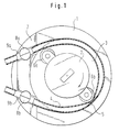
- a roller pump which consists of a Pump stator 1 and a pump rotor 2 exists.
- a pump stator 1 In the in is an essential cylindrical cavity 3 of the pump stator Hose 4 inserted so that it acts as a pump bed designated inner wall 5 of the pump stator.
- the rotatable stored rollers 6a and 6b of the pump rotor roll on the Hose piece and press it against the inner wall 5 of the Pump stator together. This will be in the hose section existing medium according to the direction of rotation (arrow) of the Pump rotor promoted.
- Hose fixation device 7 arranged by the Pump stator and thus detachable from the pump head of the roller pump is; i.e. the hose fixation device 7 is on Pump stator 1 attached, but can be removed.
- Two Fixing devices 8a and 8b are in the Hose fixation device 7 provided and insert the two Ends of the hose section 4 led out of the pump stator firmly.
- the with the hose fixing device 7 according to the invention equipped roller pump differs in their Not using conventional roller pumps.
- the piece of tubing can be placed in the pump bed and with With the help of the fixing directions 8a and 8b.
- the detachable design of the Hose fixation device 7 an exchange alone this Module, so that different fixing devices 8a and 8b can be used on one and the same pump head.
- Sensors (not shown) are provided, which with the Hose fixation device 7 are connected and with it on Pump head can be attached.
- the sensors are preferably in Receptacles inserted or in the hose fixation device embedded. In particular the last mentioned configuration enables a protected against damage and at the same time precise location of the sensors.
- FIGS. 2B and 2C is the hose fixation device 7 from Fig. 1 shown in different views.
- FIGS. 2B and 2C show the two channels 9a for the two Ends of the hose section.
- recordings 10a designed for one clamping element each.
- 2A is one the recordings 10a / b shown in a sectional view.
- At the bottom of the receptacles 10a / b grooves 12a / b are provided to align the Clamping element in the receptacle serve what is related the clamping element is described in more detail.
- the hose fixing device 7 has two grooves 13a / b of which a groove 13a in a partially cut Representation is shown in Fig. 2c.
- the grooves 13a / b serve for fastening the hose fixation device 7 on Pump stator 1 (Fig. 1).
- Corresponding to the pump stator Shaped projections provided in the grooves 13a / b of the Hose fixation device insertable and slidable therein are.
- the hose fixing device 7 is from above on the Projections attached and lowered onto the pump stator, the projections slide in the grooves 13a / b.
- a clamping element 14 is shown, which in one of the two recordings 9a / b (Fig. 2A-2C) can be used.
- the Clamping element has an opening 15 with a diameter that is a little bit smaller than the diameter of the tube piece, which is inserted into the roller pump.
- To the hose piece in to be able to insert the opening 15 of the clamping element 14 is Clamping element divided into two parts via a hinge 16 pivotable with one another on the underside of the clamping element are connected.
- the hinge 16 is on the groove 12a / b (Fig. 2C) adjusted at the bottom of the recordings so that an orientation of the Clamping element in the receptacle 9a / b by the interaction of the Hinge 16 and the groove 12a / b takes place.
- a circumferential bead 17 is located above the passage opening 15 provided as a counterpart to the circumferential groove 11 in the Recording 10a / b (Fig. 2A) the second part of the locking device represents. If the clamping element 14 with the in Passage opening 15 inserted hose into one of the Recordings 9a / b is inserted due to the conical shape of the clamping element and the receptacle the hose piece in the Passage opening 15 clamped. The bead 17 of the Clamping element snaps into the groove 11; recording one, at the same time the clamping element is due to the interaction of the Hinge 16 and the groove 12a / b aligned.
- the clamping element preferably has a grip area 18, an insertion and removal of the clamping element simplified.
- the hose fixation device can be modified Embodiment to be equipped with recordings in the Fixing body can be used on the hose piece itself are molded.
- the fixation can alternatively also be done in that the tube piece firmly with the Hose fixation device is connected, in which it suitably designed channels, corresponding to those in Fig. 2B and 2C shown channels 9a / b of the hose fixing device is glued or molded.
Landscapes
- Engineering & Computer Science (AREA)
- Health & Medical Sciences (AREA)
- Heart & Thoracic Surgery (AREA)
- Mechanical Engineering (AREA)
- Cardiology (AREA)
- Anesthesiology (AREA)
- General Engineering & Computer Science (AREA)
- Biomedical Technology (AREA)
- Hematology (AREA)
- Life Sciences & Earth Sciences (AREA)
- Animal Behavior & Ethology (AREA)
- General Health & Medical Sciences (AREA)
- Public Health (AREA)
- Veterinary Medicine (AREA)
- Pulmonology (AREA)
- Vascular Medicine (AREA)
- External Artificial Organs (AREA)
- Reciprocating Pumps (AREA)
Description
- Fig. 1
- ein Ausführungsbeispiel einer erfindungsgemäßen Schlauchfixierungsvorrichtung an einem Pumpenkopf einer Rollenpumpe für eine Herz-Lungen-Maschine;
- Fig. 2A-2C
- das Ausführungsbeispiel der Schlauchfixierungsvorrichtung aus Fig. 1 in drei verschiedenen Ansichten; und
- Fig. 3
- ein Ausführungsbeispiel eines Klemmelements für die Schlauchfixierungsvorrichtung gemäß Fig. 1 bzw. 2A - 2C.
Claims (16)
- Schlauchfixierungsvorrichtung an einer Rollenpumpe einer Herz-Lungen-Maschine, die einen aus Pumpenstator und Pumpenrotor bestehenden Pumpenkopf aufweist, mit Fixierungseinrichtungen zur Fixierung eines in den Pumpenkopf der Rollenpumpe eingelegten Schlauchstücks,
dadurch gekennzeichnet, daß beide Enden des Schlauchstück (4) durch die Schlauchfixierungsvorrichtung (7) aus dem Pumpenkopf herausgeführt sind und die Schlauchfixierungsvorrichtung (7) zusammen mit dem fixierten Schlauchstück (4) vom Pumpenkopf (1,2) der Rollenpumpe lösbar ist. - Schlauchfixierungsvorrichtung nach Anspruch 1, dadurch gekennzeichnet, daß Nuten (13a/b) vorgesehen sind, in die zur Befestigung der Schlauchfixierungsvorrichtung (7) an dem Pumpenkopf (1,2) der Rollenpumpe Vorsprünge einführbar und darin verschiebbar sind, die an dem Pumpenstator (1) der Rollenpumpe ausgebildet sind.
- Schlauchfixierungsvorrichtung nach Anspruch 1, dadurch gekennzeichnet, daß Vorsprünge vorhanden sind, die zur Befestigung der Schlauchfixierungsvorrichtung (7) an dem Pumpenkopf (1, 2) der Rollenpumpe in Nuten einführbar und darin verschiebbar sind, die an dem Pumpenstator (11) der Rollenpumpe ausgebildet sind.
- Schlauchfixierungsvorrichtung nach Anspruch 1, 2 oder 3, dadurch gekennzeichnet, daß Sensoren zur Messung von Eigenschaften des von der Rollenpumpe geförderten Mediums in die Schlauchfixierungsvorrichtung (7) integriert sind.
- Schlauchfixierungsvorrichtung nach Anspruch 4, dadurch gekennzeichnet, daß Aufnahmen für die Sensoren vorgesehen sind, in die die Sensoren einsetzbar sind.
- Schlauchfixierungsvorrichtung nach Anspruch 4, dadurch gekennzeichnet, daß die Sensoren in das Material der Schlauchfixierungsvorrichtung (7) eingebettet sind.
- Schlauchfixierungsvorrichtung nach einem der Ansprüche 1 bis 6, dadurch gekennzeichnet, daß innen-konische Aufnahmen (9a/b) für außen-konische Klemmelemente (14) vorgesehen sind, daß die Klemmelemente (14) aus im wesentlichen zwei Teilen bestehen und eine Öffnung (15) für die Durchführung eines Schlauches aufweisen, deren Durchmesser geringfügig kleiner als der Durchmesser des Schlauches ist, daß die zumindest beiden Teile der Klemmelemente (14) miteinander so verbunden sind, daß durch das Einstecken der Klemmelemente (14) in die Aufnahmen (9a/b) der Schlauch aufgrund des Zusammenwirkens des Innenkonus der Aufnahme und des Außenkonus des Klemmelements in der Öffnung (15) des Klemmelements eingeklemmt wird.
- Schlauchfixierungsvorrichtung nach Anspruch 7, dadurch gekennzeichnet,daß die beiden Teile der Klemmelemente (14) mittels einer scharnierartigen Einrichtung (16) verbunden sind, die an den Klemmelementen (14) so angeordnet ist, daß sie mit in den Aufnahmen vorgesehenen Führungsnuten (12a/b) zur Ausrichtung des Klemmelements in der Aufnahme zusammenwirkt.
- Schlauchfixierungsvorrichtung nach Anspruch 7 oder 8, dadurch gekennzeichnet, daß ein Filmscharnier vorgesehen ist, das die wesentlichen zwei Teile des Klemmelements (14) verbindet.
- Schlauchfixierungsvorrichtung nach Anspruch 9, dadurch gekennzeichnet, daß das Filmscharnier einstückig mit den im wesentlichen zwei Teilen des Klemmelements (14) ausgebildet ist.
- Schlauchfixierungsvorrichtung nach einem der Ansprüche 7 bis 10, dadurch gekennzeichnet, daß in den Aufnahmen (9a/b) und an den Klemmelementen (14) Rasteinrichtungen (11, 17) ausgebildet sind, die beim Einstecken der Klemmelemente in die Aufnahmen einrastbar sind.
- Schlauchfixierungsvorrichtung nach einem der Ansprüche 1 bis 6, dadurch gekennzeichnet, daß Aufnahmen für Fixierkörper vorgesehen sind, die an dem Schlauchstück angebracht sind.
- Schlauchfixierungsvorrichtung nach Anspruch 12, adurch gekennzeichnet, daß die Fixierkörper an dem Schlauchstück angeformt sind.
- Schlauchfixierungsvorrichtung nach einem der Ansprüche 1 bis 6, dadurch gekennzeichnet, daß das Schlauchstück fest mit der Schlauchfixierungsvorrichtung verbunden ist.
- Schlauchfixierungsvorrichtung nach Anspruch 14, dadurch gekennzeichnet, daß das Schlauchstück verklebt oder umspritzt ist.
- Rollenpumpe für eine Herz-Lungen-Mschine mit einer Schlauchfixierungsvorrichtung (7) nach einem der vorangegangenen Ansprüche 1 bis 15.
Priority Applications (3)
| Application Number | Priority Date | Filing Date | Title |
|---|---|---|---|
| DE59405906T DE59405906D1 (de) | 1994-02-16 | 1994-02-16 | Schlauchfixierungsvorrichtung für Rollenpumpen |
| EP94102333A EP0672830B1 (de) | 1994-02-16 | 1994-02-16 | Schlauchfixierungsvorrichtung für Rollenpumpen |
| US08/388,805 US5533877A (en) | 1994-02-16 | 1995-02-15 | Hose fastening arrangement for roller pumps |
Applications Claiming Priority (1)
| Application Number | Priority Date | Filing Date | Title |
|---|---|---|---|
| EP94102333A EP0672830B1 (de) | 1994-02-16 | 1994-02-16 | Schlauchfixierungsvorrichtung für Rollenpumpen |
Publications (2)
| Publication Number | Publication Date |
|---|---|
| EP0672830A1 EP0672830A1 (de) | 1995-09-20 |
| EP0672830B1 true EP0672830B1 (de) | 1998-05-06 |
Family
ID=8215688
Family Applications (1)
| Application Number | Title | Priority Date | Filing Date |
|---|---|---|---|
| EP94102333A Expired - Lifetime EP0672830B1 (de) | 1994-02-16 | 1994-02-16 | Schlauchfixierungsvorrichtung für Rollenpumpen |
Country Status (3)
| Country | Link |
|---|---|
| US (1) | US5533877A (de) |
| EP (1) | EP0672830B1 (de) |
| DE (1) | DE59405906D1 (de) |
Families Citing this family (24)
| Publication number | Priority date | Publication date | Assignee | Title |
|---|---|---|---|---|
| JPH1033663A (ja) * | 1996-07-25 | 1998-02-10 | Kanegafuchi Chem Ind Co Ltd | チューブ式ローラポンプ |
| DE19960668C1 (de) * | 1999-12-15 | 2001-08-16 | W O M Gmbh Physikalisch Medizi | Schlauchkasette für eine peristaltische Pumpe |
| JP4557452B2 (ja) * | 2001-03-13 | 2010-10-06 | 日本電産サーボ株式会社 | ローラポンプ |
| NZ523300A (en) | 2002-12-20 | 2005-12-23 | Impian Technologies Ltd | Peristaltic pump head and tube holder |
| DE10334516B4 (de) | 2003-07-29 | 2006-06-14 | Sorin Group Deutschland Gmbh | Anzeige- und Bedienvorrichtung für medizintechnische Geräte und Anzeige-/Bedieneinheit dafür |
| EA013552B1 (ru) * | 2004-05-14 | 2010-06-30 | Фрезениус Медикел Кэар Дойчланд Гмбх | Роторный насос |
| US8047819B2 (en) * | 2005-09-23 | 2011-11-01 | Medtronic, Inc. | Tubing holding device for roller pumps |
| EP2389967B1 (de) * | 2008-12-22 | 2013-11-13 | Terumo BCT, Inc. | Peristaltische Pumpe und Blutverarbeitungsvorrichtung mit Luftblasendetektor |
| JP5397747B2 (ja) * | 2009-02-16 | 2014-01-22 | ニプロ株式会社 | チューブポンプ |
| EP2781234A1 (de) * | 2013-03-20 | 2014-09-24 | Fresenius Medical Care Deutschland GmbH | Rohr für körperexternen Kreislauf mit doppeltem Anschlussstück |
| JP6401931B2 (ja) * | 2014-04-09 | 2018-10-10 | アトムメディカル株式会社 | 輸液装置 |
| DE102016009174B3 (de) * | 2016-07-29 | 2017-11-02 | W. O. M. World of Medicine GmbH | Schlauchkassette für eine peristaltische Pumpe mit elastischen Schenkeln |
| EP4497947A3 (de) * | 2017-09-26 | 2025-04-09 | Nipro Corporation | Schlauchset und schlauchpumpe damit |
| DE102018121903A1 (de) * | 2018-09-07 | 2020-03-12 | Fresenius Medical Care Deutschland Gmbh | Peristaltische Pumpe |
| EP3884161B1 (de) | 2018-11-20 | 2026-04-15 | LivaNova Deutschland GmbH | Rohrhaltevorrichtung für einen rollenpumpenkopf |
| JP7221522B2 (ja) | 2019-02-15 | 2023-02-14 | サーパス工業株式会社 | チューブポンプシステムおよびその制御方法 |
| JP7480982B2 (ja) | 2020-01-31 | 2024-05-10 | サーパス工業株式会社 | チューブポンプ |
| JP7461639B2 (ja) * | 2020-05-26 | 2024-04-04 | サーパス工業株式会社 | チューブポンプシステム |
| JP7480988B2 (ja) * | 2020-05-26 | 2024-05-10 | サーパス工業株式会社 | チューブ保持部材およびチューブポンプ |
| US12152578B2 (en) * | 2020-05-28 | 2024-11-26 | Fenwal, Inc. | Pump system with tube guides |
| DE102021116833A1 (de) * | 2021-06-30 | 2023-01-05 | Fresenius Medical Care Deutschland Gmbh | Klemmelement für eine Pumpvorrichtung |
| TR2022008829A2 (tr) | 2022-05-30 | 2023-12-21 | Aselsan Elektronik Sanayi Ve Ticaret As | Özelli̇kle peri̇stalti̇k pompalar i̇çi̇n bi̇r hortum tutma aparati |
| USD1069109S1 (en) | 2023-04-17 | 2025-04-01 | iMed Technology, Inc. | Feeding tube set inlet component |
| USD1055279S1 (en) | 2023-04-17 | 2024-12-24 | iMed Technology, Inc. | Feeding tube set inlet component |
Family Cites Families (17)
| Publication number | Priority date | Publication date | Assignee | Title |
|---|---|---|---|---|
| US3137240A (en) * | 1961-07-17 | 1964-06-16 | Russell G Hunt | Pumps |
| US3386630A (en) * | 1966-05-19 | 1968-06-04 | Girard S. Haviland | Dispensing apparatus |
| US3875970A (en) * | 1971-03-25 | 1975-04-08 | Manostat Corp | Tubing |
| US4452599A (en) * | 1981-10-26 | 1984-06-05 | The Hospital For Sick Children | Method of delivering medical liquid by peristaltic tube pump |
| US4537561A (en) * | 1983-02-24 | 1985-08-27 | Medical Technology, Ltd. | Peristaltic infusion pump and disposable cassette for use therewith |
| DE3326784C2 (de) * | 1983-07-25 | 1986-06-05 | Fresenius AG, 6380 Bad Homburg | Peristaltisch arbeitende Rollenpumpe |
| US4573887A (en) * | 1983-09-16 | 1986-03-04 | S. E. Rykoff & Co. | Corrosion-resistant roller-type pump |
| US4798590A (en) * | 1983-11-22 | 1989-01-17 | Medical Technology Products, Inc. | Intravenous infusion pumping system including independent pump set |
| DE8418491U1 (de) * | 1984-06-19 | 1984-09-20 | Richard Wolf Gmbh, 7134 Knittlingen | Schlauchpumpe fuer spuelfluessigkeiten |
| US4599055A (en) * | 1985-06-25 | 1986-07-08 | Cobe Laboratories, Inc. | Peristaltic pump |
| FR2594496A1 (fr) * | 1986-09-12 | 1987-08-21 | Baxter Travenol Lab | Conduit de transfert de fluides, notamment pour pompe peristaltique, et procede de realisation de celui-ci |
| US4976590A (en) * | 1988-06-08 | 1990-12-11 | Baldwin Brian E | Fluid conduit-responsively adjustable pump arrangement and pump/conduit arrangement and method, and fluid conduits therefor |
| US5062775A (en) * | 1989-09-29 | 1991-11-05 | Rocky Mountain Research, Inc. | Roller pump in an extra corporeal support system |
| US5213483A (en) * | 1991-06-19 | 1993-05-25 | Strato Medical Corporation | Peristaltic infusion pump with removable cassette and mechanically keyed tube set |
| US5267956A (en) * | 1992-02-05 | 1993-12-07 | Alcon Surgical, Inc. | Surgical cassette |
| FR2690715B1 (fr) * | 1992-04-30 | 1994-07-22 | Debiotech Sa | Pompe peristaltique a cassette munie d'un ensemble de detrompage. |
| US5433588A (en) * | 1993-12-15 | 1995-07-18 | Stryker Corporation | Peristaltic pump with one piece tubing insert and one piece cover |
-
1994
- 1994-02-16 DE DE59405906T patent/DE59405906D1/de not_active Expired - Lifetime
- 1994-02-16 EP EP94102333A patent/EP0672830B1/de not_active Expired - Lifetime
-
1995
- 1995-02-15 US US08/388,805 patent/US5533877A/en not_active Expired - Lifetime
Also Published As
| Publication number | Publication date |
|---|---|
| DE59405906D1 (de) | 1998-06-10 |
| EP0672830A1 (de) | 1995-09-20 |
| US5533877A (en) | 1996-07-09 |
Similar Documents
| Publication | Publication Date | Title |
|---|---|---|
| EP0672830A1 (de) | Schlauchfixierungsvorrichtung für Rollenpumpen | |
| DE69030132T2 (de) | Luftdetektor zur Anwendung in einer Infusionspumpe | |
| DE2933512C2 (de) | Proben-Einspritzventil | |
| DE19854874A1 (de) | Adapter zum Anschluß eines Bohrers an eine Vakuumquelle | |
| DE10342453A1 (de) | Filterpatrone mit schiwmmender Dichtung | |
| DE2434847A1 (de) | Verbindungseinrichtung an einem rotationsfaehigen koerper | |
| DE3304784A1 (de) | Vorrichtung zur umwandlung einer drehbewegung in eine linearbewegung | |
| DE20014492U1 (de) | Gleitschienenanordnung | |
| DE69818390T2 (de) | Mechanismus zur Befestigung von Druckmittel führenden Elementen an einem Rahmenelement | |
| DE102006025546B4 (de) | Molch zum Fördern eines Arbeitsmediums | |
| DE68910028T2 (de) | Halterung mit Strömungsweg für medizinischen Wärmetauscher. | |
| DE3742739C2 (de) | ||
| DE69509139T2 (de) | Filter und Filterkartusche mit freiem Zentralkern für die Filtration von Motorflüssigkeiten | |
| DE69501828T2 (de) | Hahn mit konischem küken | |
| AT402540B (de) | Ventil, insbesondere für kolbenverdichter | |
| DE1786347A1 (de) | Drehfilter | |
| DE10251644B4 (de) | Hahn | |
| DE3507290C2 (de) | Handbrausehalter | |
| DE3424577C2 (de) | Verfahren zum Festlegen einer geteilten Leuchte an einem Fahrzeug | |
| EP0285944A2 (de) | Magnetbandkassette | |
| DE29505787U1 (de) | Verschlußstück | |
| DE102008001177A1 (de) | Gelenkschutzkappe | |
| DE2256149C3 (de) | Anbohrschelle | |
| DE202012100059U1 (de) | Probenhalter | |
| DE2850744A1 (de) | Vorrichtung und spule zum auf- und abrollen eines gurtes, z.b. eines sicherheitsgurtes |
Legal Events
| Date | Code | Title | Description |
|---|---|---|---|
| PUAI | Public reference made under article 153(3) epc to a published international application that has entered the european phase |
Free format text: ORIGINAL CODE: 0009012 |
|
| AK | Designated contracting states |
Kind code of ref document: A1 Designated state(s): DE FR GB IT |
|
| 17P | Request for examination filed |
Effective date: 19960129 |
|
| 17Q | First examination report despatched |
Effective date: 19960605 |
|
| GRAG | Despatch of communication of intention to grant |
Free format text: ORIGINAL CODE: EPIDOS AGRA |
|
| GRAG | Despatch of communication of intention to grant |
Free format text: ORIGINAL CODE: EPIDOS AGRA |
|
| GRAH | Despatch of communication of intention to grant a patent |
Free format text: ORIGINAL CODE: EPIDOS IGRA |
|
| GRAH | Despatch of communication of intention to grant a patent |
Free format text: ORIGINAL CODE: EPIDOS IGRA |
|
| GRAA | (expected) grant |
Free format text: ORIGINAL CODE: 0009210 |
|
| AK | Designated contracting states |
Kind code of ref document: B1 Designated state(s): DE FR GB IT |
|
| GBT | Gb: translation of ep patent filed (gb section 77(6)(a)/1977) |
Effective date: 19980506 |
|
| REF | Corresponds to: |
Ref document number: 59405906 Country of ref document: DE Date of ref document: 19980610 |
|
| ET | Fr: translation filed | ||
| ITF | It: translation for a ep patent filed | ||
| PLBE | No opposition filed within time limit |
Free format text: ORIGINAL CODE: 0009261 |
|
| STAA | Information on the status of an ep patent application or granted ep patent |
Free format text: STATUS: NO OPPOSITION FILED WITHIN TIME LIMIT |
|
| 26N | No opposition filed | ||
| REG | Reference to a national code |
Ref country code: GB Ref legal event code: IF02 |
|
| REG | Reference to a national code |
Ref country code: FR Ref legal event code: CD Ref country code: FR Ref legal event code: CA |
|
| PGFP | Annual fee paid to national office [announced via postgrant information from national office to epo] |
Ref country code: IT Payment date: 20120222 Year of fee payment: 19 |
|
| PGFP | Annual fee paid to national office [announced via postgrant information from national office to epo] |
Ref country code: DE Payment date: 20130213 Year of fee payment: 20 Ref country code: FR Payment date: 20130301 Year of fee payment: 20 Ref country code: GB Payment date: 20130213 Year of fee payment: 20 |
|
| REG | Reference to a national code |
Ref country code: DE Ref legal event code: R071 Ref document number: 59405906 Country of ref document: DE |
|
| REG | Reference to a national code |
Ref country code: GB Ref legal event code: PE20 Expiry date: 20140215 |
|
| PG25 | Lapsed in a contracting state [announced via postgrant information from national office to epo] |
Ref country code: DE Free format text: LAPSE BECAUSE OF EXPIRATION OF PROTECTION Effective date: 20140218 Ref country code: GB Free format text: LAPSE BECAUSE OF EXPIRATION OF PROTECTION Effective date: 20140215 |