EP0670739B1 - Saugpumpe zum ableiten von körperflüssigkeiten aus körperhöhlungen - Google Patents
Saugpumpe zum ableiten von körperflüssigkeiten aus körperhöhlungen Download PDFInfo
- Publication number
- EP0670739B1 EP0670739B1 EP92903502A EP92903502A EP0670739B1 EP 0670739 B1 EP0670739 B1 EP 0670739B1 EP 92903502 A EP92903502 A EP 92903502A EP 92903502 A EP92903502 A EP 92903502A EP 0670739 B1 EP0670739 B1 EP 0670739B1
- Authority
- EP
- European Patent Office
- Prior art keywords
- pump
- pump body
- bottom portion
- suction
- suction pump
- Prior art date
- Legal status (The legal status is an assumption and is not a legal conclusion. Google has not performed a legal analysis and makes no representation as to the accuracy of the status listed.)
- Expired - Lifetime
Links
Images



Classifications
-
- A—HUMAN NECESSITIES
- A61—MEDICAL OR VETERINARY SCIENCE; HYGIENE
- A61M—DEVICES FOR INTRODUCING MEDIA INTO, OR ONTO, THE BODY; DEVICES FOR TRANSDUCING BODY MEDIA OR FOR TAKING MEDIA FROM THE BODY; DEVICES FOR PRODUCING OR ENDING SLEEP OR STUPOR
- A61M1/00—Suction or pumping devices for medical purposes; Devices for carrying-off, for treatment of, or for carrying-over, body-liquids; Drainage systems
- A61M1/80—Suction pumps
- A61M1/82—Membrane pumps, e.g. bulbs
-
- A—HUMAN NECESSITIES
- A61—MEDICAL OR VETERINARY SCIENCE; HYGIENE
- A61M—DEVICES FOR INTRODUCING MEDIA INTO, OR ONTO, THE BODY; DEVICES FOR TRANSDUCING BODY MEDIA OR FOR TAKING MEDIA FROM THE BODY; DEVICES FOR PRODUCING OR ENDING SLEEP OR STUPOR
- A61M1/00—Suction or pumping devices for medical purposes; Devices for carrying-off, for treatment of, or for carrying-over, body-liquids; Drainage systems
- A61M1/60—Containers for suction drainage, adapted to be used with an external suction source
- A61M1/63—Containers for suction drainage, adapted to be used with an external suction source with means for emptying the suction container, e.g. by interrupting suction
-
- A—HUMAN NECESSITIES
- A61—MEDICAL OR VETERINARY SCIENCE; HYGIENE
- A61M—DEVICES FOR INTRODUCING MEDIA INTO, OR ONTO, THE BODY; DEVICES FOR TRANSDUCING BODY MEDIA OR FOR TAKING MEDIA FROM THE BODY; DEVICES FOR PRODUCING OR ENDING SLEEP OR STUPOR
- A61M1/00—Suction or pumping devices for medical purposes; Devices for carrying-off, for treatment of, or for carrying-over, body-liquids; Drainage systems
- A61M1/64—Containers with integrated suction means
- A61M1/68—Containers incorporating a flexible member creating suction
Definitions
- the present invention relates to a suction pump for draining body fluids from body cavities, said suction pump comprising a bottom portion and a domed resilient pump body having a substantially smooth inner surface, said pump body being connected to the bottom portion along its rim and forming a pumping chamber between the bottom portion and pump body, which suction pump further comprises an inlet valve and an outlet valve, said resilient pump body being resiliently deformable by manual action from its domed configuration towards the bottom portion for the provision of the pressure stroke of the suction pump and due to its elasticity returning to its domed configuration when relieved for the provision of the suction stroke of the pump.
- a pump of the type mentioned above is disclosed in EP patent No. 0270205.
- the domed pump body of the said pump has a flat top which may be supported along its inner surface by means of two sets of intersecting ridges and the bottom portion is flat and may be provided with a set of upwardly extending ridges.
- the bottom and the inner surface of the pump body are spaced, and hence the pump has a large pump clearance volume which results in that only a relatively small part of the pump chamber is used in the pumping operation.
- the prior art pump is implantable and serves to transport body fluid from one cavity of the body into another when activated.
- the ridges of the pump body if provided, serve to quickly return the pump body to its starting position.
- Similar pumps having an internally smooth domed pump body and a flat bottom portion are disclosed in GB 1,146,413 and GB 1,173,071.
- the spherical segment has an arc measure ranging between about 100° and 140°, expediently between 110° and 130°, and preferably being about 120°.
- a further embodiment of the pump according to the invention is characterized in that at its top the spherical segment has a slightly smaller radius of curvature than at its sides. This embodiment has been found to provide a satisfactory equalization of the variations in pressure which may occur during the suction stroke.
- the inlet valve and the outlet valve are offset in relation to the rim of the pump body and connected to the pump chamber through channels in the concave portion of the bottom portion. This results in that the valves and the inlets of said valves are prevented from hindering the aimed deformation of the pump body.
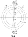
- FIG. 1 designates a bottom portion of the pump shown and 2 a pump body.
- the pump body has a domed configuration and substantially the form of a spherical segment.
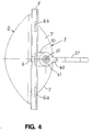
- the inner surface of the pump body is substantially smooth as will appear from Fig. 6, and along the circumference of the pump body a bead construction 3 is provided which is embedded in a rim portion 4 of the bottom portion, as will also appear from Fig. 6, said rim portion being profiled so as to correspond to the bead construction 3.
- the latter is kept in position in relation to the rim portion 4 by means of a holding ring 5 running along the entire circumference of the pump body 2 and being provided at its top with a suspension hook 6. Additional hooks 6a and 6b are provided at either side of the hook 6.
- the bottom portion 1 has substantially the form of a cup 7, the inner surface of said cup having a concave configuration along the portion 8 of the bottom portion located within the rim portion 4.
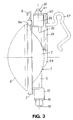
- the back of the cup 7 has two bulges 9 and 10, respectively, cf. Fig. 3, which extend flush with each other along a diameter of the cup. These bulges substantially have a U-shape and thus form internal channels 11 and 12, respectively, Fig. 6, which debouch along the concave inner surface of the portion 8.
- the bulge 9 is provided with a collar 15 which is offset backwards in relation to the rim of the pump body and comprises therein a valve holder 16 for an outlet valve 17.
- the holder 16 is provided with a nozzle 18 which is intended for mounting of a hose which is connected to a collection reservoir.
- the valve 17 only allows flow from the pump chamber 19 formed between the bottom portion 1 and the pump body 2.
- the valve is made of an elastic plastics material and has a tubular form at the top which downwardly passes into converging sides 20, 21 having adjoining downward facing edges 22, 23, which in case of overpressure in the pump chamber 19 are moved away from each other to allow discharge of fluid from the pump chamber. In case of underpressure in the pump chamber the edges 22, 23 are pressed together.
- valve 17 At its interior end the valve 17 has a circumferential flange 24 which is maintained by the corresponding upward facing edge of the holder 16.
- the valve 17 communicates with the channel 11 through an aperture 25 and the width of the channel 11 (as seen perpendicularly to the plane of the drawing in Fig. 6) corresponds substantially to the diameter of the aperture 25, the channel 11 thus being very narrow.
- the bulge 10 is provided with an inlet valve corresponding substantially to the outlet valve described above and consisting of a collar 26 in which a valve 27 having the same construction as the valve 17 is mounted, but which serves as an inlet valve, the edges 29,30 at the ends of the side walls 31, 32 of the valve turning inwards towards the pump chamber 19.
- the inlet valve is offset backwards in relation to the rim of the pump body and communicates with the channel 12 through an aperture 34, and the width of the channel 12 (seen perpendicularly to the plane of the drawing in Fig. 6) corresponds substantially to the diameter of the said aperture.
- the inlet valve is also provided with a nozzle 35 which is intended for securing one end of a connecting hose, the other end of which is coupled to a drainage tube in which a underpressure is generated after it has been positioned in the body cavity to drain the body cavity of body fluids. It will immediately be understood that the suction pressure in the pump chamber causes the inlet valve to be opened and the overpressure in the pump chamber causes the said valve to be closed.
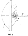
- the pump shown is provided with a suspension arrangement 37 in the form of a hook, which e.g. can be suspended from a hospital bed or equipment provided therefor.
- the hook is provided with a shank 38 having its upper end provided with a hole in which a spigot 39 engages on a protrusion 40 on the valve holder 41, whereas the lower end 42 of the shank is supported by means of a cam arrangement 43 engaging with recesses in a projection 44 on the outside of the bottom of the cup approximately at the centre of the latter.
- the cam arrangement is arranged in a manner which allows the hook 37 to be swung to one side or the other towards the pump so as to take up only little space. At the position shown in the drawing the hook is maintained by the elastically releasable engagement of one of the cams in the cam arrangement with a corresponding recess in the projection 44.
- the interior of the bottom portion has substantially a spherical segment-shaped surface 8a.
- the inner surface of the pump body 2 has approximately the configuration of a spherical segment.
- said spherical segment has a central angle of about 120° but it may vary between 100° and 140°, expediently between 110° and 130°.
- the pump body does not have the exact form of a spherical segment, the radius of curvature at the top of the pump body being slightly smaller than the radius of curvature along the sides of the pump body.
- the concave inner surface of the portion 8 extends approximately along a central arc measure of about 115°. It is noted that this inner surface does not have the exact form of a spherical segment either, said inner side also having a slightly smaller radius of curvature along its centre area 8a than along its sides.
- the arc measure of the inner surface of the portion 8 may also vary, expediently between 95° and 135°, preferably between 105° and 115°.
- the pump shown operates in the following manner:
- the pump body 2 is manually pressed inwards.
- the configuration of the inner surface of the pump body and the configuration of the inner surface of the portion 8 allow the pump body to be pressed into close engagement with the inner surface of the portion 8 so that a pump clearance volume is formed corresponding substantially to the volume of the channels 11,12, which are relatively narrow as explained above.
- the pump body 2 gradually returns to the shape shown in Fig. 6 during which it is removed from the inner surface of the portion 8 while producing a constant suction.
Landscapes
- Health & Medical Sciences (AREA)
- Heart & Thoracic Surgery (AREA)
- Animal Behavior & Ethology (AREA)
- General Health & Medical Sciences (AREA)
- Anesthesiology (AREA)
- Biomedical Technology (AREA)
- Hematology (AREA)
- Life Sciences & Earth Sciences (AREA)
- Vascular Medicine (AREA)
- Engineering & Computer Science (AREA)
- Public Health (AREA)
- Veterinary Medicine (AREA)
- Details Of Reciprocating Pumps (AREA)
- External Artificial Organs (AREA)
- Extraction Or Liquid Replacement (AREA)
- Reciprocating Pumps (AREA)
- Structures Of Non-Positive Displacement Pumps (AREA)
Claims (5)
- Saugpumpe zum Ableiten von Körperflüssigkeiten aus Körperhöhlungen, wobei die Saugpumpe einen Bodenabschnitt (1) und einen gewölbten, federnden Pumpkörper (2) aufweist, der eine im wesentlichen glatte Innenfläche hat, wobei der Pumpkörper mit dem Bodenabschnitt (1) entlang seiner Randzone (3) verbunden ist und eine Pumpkammer (19) zwischen dem Bodenabschnitt (1) und dem Pumpkörper (2) bildet, wobei die Saugpumpe außerdem ein Einlaßventil (27) und ein Auslaßventil (17) aufweist, wobei der federnde Pumpkörper (2) durch manuelles Einwirken von seiner gewölbten Konfiguration zum Bodenabschnitt hin federnd verformbar ist, um den Druckhub der Saugpumpe zu liefern, und er aufgrund seiner Elastizität zu seiner gewölbten Konfiguration zurückkehrt, wenn er freigegeben wird, um den Saughub der Pumpe zu liefern, dadurch gekennzeichnet, daß der Bodenabschnitt (1) einen konkaven Abschnitt (8) hat, der im wesentlichen der inneren Konfiguration des Pumpkörpers (2) in dessen verformten Zustand entspricht.
- Saugpumpe gemäß Anspruch 1, dadurch gekennzeichnet, daß in dem gewölbten Zustand des Pumpkörpers (2) die Innenfläche des Pumpkörpers im wesentlichen die Form eines kugelförmigen Segmentes hat.
- Saugpumpe gemäß Anspruch 2, dadurch gekennzeichnet, daß das kugelförmige Segment ein Bogenmaß zwischen ca. 100° und ca. 140°, zweckmäßig zwischen ca. 110° und ca. 130° und vorzugsweise von ca. 120° hat.
- Saugpumpe gemäß Anspruch 2, dadurch gekennzeichnet, daß das kugelförmige Segment an seiner Spitze einen geringfügig kleineren Rundungsradius als an seinen Seiten hat.
- Saugpumpe gemäß Anspruch 1, dadurch gekennzeichnet, daß das Einlaßventil (27) und das Auslaßventil (17) bezüglich der Randzone (3) des Pumpkörpers (2) quer versetzt und mit der Pumpkammer (19) durch Kanäle (11, 12) in dem konkaven Abschnitt des Bodenabschnittes (1) verbunden sind.
Applications Claiming Priority (3)
| Application Number | Priority Date | Filing Date | Title |
|---|---|---|---|
| DK83/91 | 1991-01-18 | ||
| DK008391A DK8391A (da) | 1991-01-18 | 1991-01-18 | Sugepumpe til brug ved udsugning af legemsvaeske fra kropshulrum |
| PCT/DK1992/000013 WO1992012740A1 (en) | 1991-01-18 | 1992-01-17 | Suction pump for draining body fluids from body cavities |
Publications (2)
| Publication Number | Publication Date |
|---|---|
| EP0670739A1 EP0670739A1 (de) | 1995-09-13 |
| EP0670739B1 true EP0670739B1 (de) | 1996-09-25 |
Family
ID=8089539
Family Applications (1)
| Application Number | Title | Priority Date | Filing Date |
|---|---|---|---|
| EP92903502A Expired - Lifetime EP0670739B1 (de) | 1991-01-18 | 1992-01-17 | Saugpumpe zum ableiten von körperflüssigkeiten aus körperhöhlungen |
Country Status (9)
| Country | Link |
|---|---|
| US (1) | US5472325A (de) |
| EP (1) | EP0670739B1 (de) |
| JP (1) | JP3184524B2 (de) |
| AT (1) | ATE143270T1 (de) |
| AU (1) | AU1183792A (de) |
| DE (1) | DE69214168T2 (de) |
| DK (2) | DK8391A (de) |
| ES (1) | ES2094901T3 (de) |
| WO (1) | WO1992012740A1 (de) |
Families Citing this family (27)
| Publication number | Priority date | Publication date | Assignee | Title |
|---|---|---|---|---|
| EP0592730A1 (de) * | 1992-10-15 | 1994-04-20 | Inmed Limitada | Tragbare wegwerfbare Vorrichtung zum postoperativem Absaugen |
| US6877713B1 (en) | 1999-07-20 | 2005-04-12 | Deka Products Limited Partnership | Tube occluder and method for occluding collapsible tubes |
| AU2004293815B2 (en) | 2003-11-20 | 2010-07-22 | The Henry M. Jackson Foundation For The Advancement Of Military Medicine, Inc. | Portable hand pump for evacuation of fluids |
| US7261525B2 (en) * | 2004-09-01 | 2007-08-28 | Dielectrics Industries, Inc. | Outlet check valve for fluid bladders |
| US8337475B2 (en) | 2004-10-12 | 2012-12-25 | C. R. Bard, Inc. | Corporeal drainage system |
| US8177772B2 (en) * | 2005-09-26 | 2012-05-15 | C. R. Bard, Inc. | Catheter connection systems |
| US7794141B2 (en) | 2006-04-14 | 2010-09-14 | Deka Products Limited Partnership | Thermal and coductivity sensing systems, devices and methods |
| US10537671B2 (en) | 2006-04-14 | 2020-01-21 | Deka Products Limited Partnership | Automated control mechanisms in a hemodialysis apparatus |
| US20140199193A1 (en) | 2007-02-27 | 2014-07-17 | Deka Products Limited Partnership | Blood treatment systems and methods |
| US8409441B2 (en) | 2007-02-27 | 2013-04-02 | Deka Products Limited Partnership | Blood treatment systems and methods |
| CA2681912C (en) | 2007-02-27 | 2015-09-29 | Deka Products Limited Partnership | Hemodialysis systems and methods |
| US9028691B2 (en) | 2007-02-27 | 2015-05-12 | Deka Products Limited Partnership | Blood circuit assembly for a hemodialysis system |
| US8366655B2 (en) | 2007-02-27 | 2013-02-05 | Deka Products Limited Partnership | Peritoneal dialysis sensor apparatus systems, devices and methods |
| JP5634863B2 (ja) * | 2007-05-22 | 2014-12-03 | メデラ ホールディング アーゲー | ドレナージポンプユニット |
| US8863772B2 (en) | 2008-08-27 | 2014-10-21 | Deka Products Limited Partnership | Occluder for a medical infusion system |
| EP3620191B1 (de) | 2008-01-23 | 2023-12-13 | DEKA Products Limited Partnership | Vorrichtung zum automatischen anschluss an eine flüssigkeitsleitung und verfahren für ein medizinisches behandlungssystem |
| US10201647B2 (en) | 2008-01-23 | 2019-02-12 | Deka Products Limited Partnership | Medical treatment system and methods using a plurality of fluid lines |
| US11833281B2 (en) | 2008-01-23 | 2023-12-05 | Deka Products Limited Partnership | Pump cassette and methods for use in medical treatment system using a plurality of fluid lines |
| SG195155A1 (en) | 2011-05-24 | 2013-12-30 | Deka Products Lp | Blood treatment systems and methods |
| US9364655B2 (en) | 2012-05-24 | 2016-06-14 | Deka Products Limited Partnership | Flexible tubing occlusion assembly |
| EP3151877B1 (de) | 2014-06-05 | 2020-04-15 | DEKA Products Limited Partnership | System zur berechnung einer änderung in einem flüssigkeitsvolumen in einer pumpenkammer |
| AU2017299466B2 (en) | 2016-07-18 | 2022-07-14 | Merit Medical Systems, Inc. | Inflatable radial artery compression device |
| JP7131742B2 (ja) | 2016-09-29 | 2022-09-06 | メリット・メディカル・システムズ・インコーポレイテッド | 血管プロテーゼを受容し、その展開を補助するための柔軟部材 |
| EP4467111A3 (de) | 2017-03-15 | 2025-03-05 | Merit Medical Systems, Inc. | Transluminale stents |
| US12484911B2 (en) | 2020-08-13 | 2025-12-02 | Merit Medical Systems, Inc. | Inflatable radial artery compression device with cinching wristband and method of use |
| US12426864B2 (en) | 2021-06-18 | 2025-09-30 | Merit Medical Systems, Inc. | Hemostasis devices and methods of use |
| US20250027493A1 (en) * | 2023-07-20 | 2025-01-23 | Dongguan Shengzai Electronic Technology Co., Ltd. | Pump body assembly and booster energy-saving water pump with the same |
Family Cites Families (16)
| Publication number | Priority date | Publication date | Assignee | Title |
|---|---|---|---|---|
| FR1206966A (fr) * | 1958-05-24 | 1960-02-12 | Kigass Ltd | Pompe à commande manuelle |
| US3127846A (en) * | 1960-02-16 | 1964-04-07 | Kerns Homer | Artificial blood pump means |
| US3111125A (en) * | 1961-11-06 | 1963-11-19 | Rudolf R Schulte | Drainage device |
| NL134323C (de) * | 1966-02-09 | |||
| US3452757A (en) * | 1966-09-14 | 1969-07-01 | Dow Corning | Two-way flushing device for treatment of hydrocephalus |
| DE1812711C3 (de) * | 1967-12-05 | 1978-08-31 | Orthopedic Equipment Co. Inc., Bourbon, Ind. (V.St.A.) | Chirurgisches Absauggerät |
| US3496872A (en) * | 1968-05-31 | 1970-02-24 | Trico Products Corp | Rotary motor driven pump |
| US3588293A (en) * | 1969-11-25 | 1971-06-28 | Juan Alberto Morales | Concavo-convex siphoning pump |
| US3947156A (en) * | 1972-03-08 | 1976-03-30 | Erich Becker | Diaphragm pump, particularly for the generation of vacuum |
| US4290346A (en) * | 1979-04-30 | 1981-09-22 | Abbott Laboratories | Intravenous pump chamber |
| US4479761A (en) * | 1982-12-28 | 1984-10-30 | Baxter Travenol Laboratories, Inc. | Actuator apparatus for a prepackaged fluid processing module having pump and valve elements operable in response to externally applied pressures |
| DE3408331C2 (de) * | 1984-03-07 | 1986-06-12 | Fresenius AG, 6380 Bad Homburg | Pumpanordnung für medizinische Zwecke |
| US4657490A (en) * | 1985-03-27 | 1987-04-14 | Quest Medical, Inc. | Infusion pump with disposable cassette |
| US4850955A (en) * | 1986-12-02 | 1989-07-25 | Codman & Shurtleff | Body fluid transfer device |
| IL83259A (en) * | 1987-07-20 | 1992-05-25 | D F Lab Ltd | Disposable cell and diaphragm pump for use of same |
| US5152753A (en) * | 1990-04-02 | 1992-10-06 | Pudenz-Schulte Medical Research Corporation | Medication infusion device with dose recharge restriction |
-
1991
- 1991-01-18 DK DK008391A patent/DK8391A/da not_active Application Discontinuation
-
1992
- 1992-01-17 DE DE69214168T patent/DE69214168T2/de not_active Expired - Lifetime
- 1992-01-17 EP EP92903502A patent/EP0670739B1/de not_active Expired - Lifetime
- 1992-01-17 ES ES92903502T patent/ES2094901T3/es not_active Expired - Lifetime
- 1992-01-17 US US08/050,247 patent/US5472325A/en not_active Expired - Lifetime
- 1992-01-17 AU AU11837/92A patent/AU1183792A/en not_active Abandoned
- 1992-01-17 AT AT92903502T patent/ATE143270T1/de not_active IP Right Cessation
- 1992-01-17 JP JP50347092A patent/JP3184524B2/ja not_active Expired - Lifetime
- 1992-01-17 DK DK92903502.0T patent/DK0670739T3/da active
- 1992-01-17 WO PCT/DK1992/000013 patent/WO1992012740A1/en not_active Ceased
Also Published As
| Publication number | Publication date |
|---|---|
| JPH06504468A (ja) | 1994-05-26 |
| DK8391A (da) | 1992-07-19 |
| EP0670739A1 (de) | 1995-09-13 |
| WO1992012740A1 (en) | 1992-08-06 |
| DK0670739T3 (da) | 1997-02-24 |
| US5472325A (en) | 1995-12-05 |
| AU1183792A (en) | 1992-08-27 |
| DE69214168D1 (de) | 1996-10-31 |
| DK8391D0 (da) | 1991-01-18 |
| JP3184524B2 (ja) | 2001-07-09 |
| ATE143270T1 (de) | 1996-10-15 |
| DE69214168T2 (de) | 1998-02-05 |
| ES2094901T3 (es) | 1997-02-01 |
Similar Documents
| Publication | Publication Date | Title |
|---|---|---|
| US5472325A (en) | Suction pump for draining body fluids from body cavities | |
| US7666162B2 (en) | Breast cup | |
| TW422744B (en) | Trigger actuated pump sprayer | |
| US4111204A (en) | Suction collection system | |
| US4745641A (en) | Toilet bowl plunger | |
| US5314116A (en) | Pulsator for irrigation systems and the like | |
| US7013499B2 (en) | Toilet and sink drain plunger | |
| USRE29321E (en) | Fluid collection bottle and improvements therein | |
| US4622702A (en) | Drain plunger | |
| US4831669A (en) | Plunger splash guard for a toilet bowl | |
| JPH07317661A (ja) | 流体吸入ポンプ機構 | |
| JP2004507219A (ja) | ライナー | |
| US5020166A (en) | Multi-purpose water pressure plunger | |
| US20030106872A1 (en) | Nipple with air intake valve | |
| EP0233961A1 (de) | Gerät zum Entstopfen von Toilettenbecken | |
| EP0232571A1 (de) | Spender für flüssige Seife | |
| KR200481587Y1 (ko) | 양변기용 압축기 | |
| US12077953B2 (en) | Flexible plunger boot | |
| KR20090001639U (ko) | 막힘 소통용 압축기 | |
| US5261128A (en) | Multi-purpose water pressure plunger | |
| US5287564A (en) | Multi-purpose water pressure plunger | |
| CN213975249U (zh) | 一种乳液罐用泵头结构 | |
| WO2001006066A1 (en) | Improved elephant-nosed toilet plunger | |
| JPH0912052A (ja) | ポンプディスペンサー | |
| JP3614608B2 (ja) | 縦形ポンプ式の液体噴出器 |
Legal Events
| Date | Code | Title | Description |
|---|---|---|---|
| PUAI | Public reference made under article 153(3) epc to a published international application that has entered the european phase |
Free format text: ORIGINAL CODE: 0009012 |
|
| 17P | Request for examination filed |
Effective date: 19930406 |
|
| AK | Designated contracting states |
Kind code of ref document: A1 Designated state(s): AT BE CH DE DK ES FR GB GR IT LI LU MC NL SE |
|
| 17Q | First examination report despatched |
Effective date: 19951024 |
|
| GRAH | Despatch of communication of intention to grant a patent |
Free format text: ORIGINAL CODE: EPIDOS IGRA |
|
| GRAH | Despatch of communication of intention to grant a patent |
Free format text: ORIGINAL CODE: EPIDOS IGRA |
|
| GRAH | Despatch of communication of intention to grant a patent |
Free format text: ORIGINAL CODE: EPIDOS IGRA |
|
| GRAA | (expected) grant |
Free format text: ORIGINAL CODE: 0009210 |
|
| AK | Designated contracting states |
Kind code of ref document: B1 Designated state(s): AT BE CH DE DK ES FR GB GR IT LI LU MC NL SE |
|
| PG25 | Lapsed in a contracting state [announced via postgrant information from national office to epo] |
Ref country code: NL Free format text: LAPSE BECAUSE OF FAILURE TO SUBMIT A TRANSLATION OF THE DESCRIPTION OR TO PAY THE FEE WITHIN THE PRESCRIBED TIME-LIMIT Effective date: 19960925 Ref country code: LI Effective date: 19960925 Ref country code: GR Free format text: LAPSE BECAUSE OF FAILURE TO SUBMIT A TRANSLATION OF THE DESCRIPTION OR TO PAY THE FEE WITHIN THE PRESCRIBED TIME-LIMIT Effective date: 19960925 Ref country code: CH Effective date: 19960925 Ref country code: BE Effective date: 19960925 Ref country code: AT Effective date: 19960925 |
|
| REF | Corresponds to: |
Ref document number: 143270 Country of ref document: AT Date of ref document: 19961015 Kind code of ref document: T |
|
| ITPR | It: changes in ownership of a european patent |
Owner name: C.NE EPO REG. 20;MAERSK MEDICAL A/S |
|
| REF | Corresponds to: |
Ref document number: 69214168 Country of ref document: DE Date of ref document: 19961031 |
|
| ITF | It: translation for a ep patent filed | ||
| RAP2 | Party data changed (patent owner data changed or rights of a patent transferred) |
Owner name: MAERSK MEDICAL A/S |
|
| ET | Fr: translation filed | ||
| PG25 | Lapsed in a contracting state [announced via postgrant information from national office to epo] |
Ref country code: LU Free format text: LAPSE BECAUSE OF NON-PAYMENT OF DUE FEES Effective date: 19970131 |
|
| REG | Reference to a national code |
Ref country code: ES Ref legal event code: FG2A Ref document number: 2094901 Country of ref document: ES Kind code of ref document: T3 |
|
| REG | Reference to a national code |
Ref country code: DK Ref legal event code: T3 |
|
| NLT2 | Nl: modifications (of names), taken from the european patent patent bulletin |
Owner name: MAERSK MEDICAL A/S |
|
| NLV1 | Nl: lapsed or annulled due to failure to fulfill the requirements of art. 29p and 29m of the patents act | ||
| REG | Reference to a national code |
Ref country code: CH Ref legal event code: PL |
|
| PG25 | Lapsed in a contracting state [announced via postgrant information from national office to epo] |
Ref country code: MC Effective date: 19970731 |
|
| PLBE | No opposition filed within time limit |
Free format text: ORIGINAL CODE: 0009261 |
|
| STAA | Information on the status of an ep patent application or granted ep patent |
Free format text: STATUS: NO OPPOSITION FILED WITHIN TIME LIMIT |
|
| 26N | No opposition filed | ||
| REG | Reference to a national code |
Ref country code: GB Ref legal event code: 732E |
|
| REG | Reference to a national code |
Ref country code: GB Ref legal event code: IF02 |
|
| PG25 | Lapsed in a contracting state [announced via postgrant information from national office to epo] |
Ref country code: IT Free format text: LAPSE BECAUSE OF NON-PAYMENT OF DUE FEES;WARNING: LAPSES OF ITALIAN PATENTS WITH EFFECTIVE DATE BEFORE 2007 MAY HAVE OCCURRED AT ANY TIME BEFORE 2007. THE CORRECT EFFECTIVE DATE MAY BE DIFFERENT FROM THE ONE RECORDED. Effective date: 20050117 |
|
| PGRI | Patent reinstated in contracting state [announced from national office to epo] |
Ref country code: IT Effective date: 20080301 |
|
| PGFP | Annual fee paid to national office [announced via postgrant information from national office to epo] |
Ref country code: DK Payment date: 20110112 Year of fee payment: 20 |
|
| PGFP | Annual fee paid to national office [announced via postgrant information from national office to epo] |
Ref country code: IT Payment date: 20110125 Year of fee payment: 20 Ref country code: FR Payment date: 20110202 Year of fee payment: 20 Ref country code: SE Payment date: 20110113 Year of fee payment: 20 Ref country code: DE Payment date: 20110121 Year of fee payment: 20 |
|
| PGFP | Annual fee paid to national office [announced via postgrant information from national office to epo] |
Ref country code: GB Payment date: 20110120 Year of fee payment: 20 Ref country code: ES Payment date: 20110125 Year of fee payment: 20 |
|
| REG | Reference to a national code |
Ref country code: DE Ref legal event code: R071 Ref document number: 69214168 Country of ref document: DE |
|
| REG | Reference to a national code |
Ref country code: DE Ref legal event code: R071 Ref document number: 69214168 Country of ref document: DE |
|
| REG | Reference to a national code |
Ref country code: DK Ref legal event code: EUP |
|
| REG | Reference to a national code |
Ref country code: GB Ref legal event code: PE20 Expiry date: 20120116 |
|
| REG | Reference to a national code |
Ref country code: SE Ref legal event code: EUG |
|
| PG25 | Lapsed in a contracting state [announced via postgrant information from national office to epo] |
Ref country code: DE Free format text: LAPSE BECAUSE OF EXPIRATION OF PROTECTION Effective date: 20120118 |
|
| PG25 | Lapsed in a contracting state [announced via postgrant information from national office to epo] |
Ref country code: GB Free format text: LAPSE BECAUSE OF EXPIRATION OF PROTECTION Effective date: 20120116 |
|
| REG | Reference to a national code |
Ref country code: ES Ref legal event code: FD2A Effective date: 20130805 |
|
| PG25 | Lapsed in a contracting state [announced via postgrant information from national office to epo] |
Ref country code: ES Free format text: LAPSE BECAUSE OF EXPIRATION OF PROTECTION Effective date: 20120118 |