EP0670477A2 - Measurement system - Google Patents
Measurement system Download PDFInfo
- Publication number
- EP0670477A2 EP0670477A2 EP95107583A EP95107583A EP0670477A2 EP 0670477 A2 EP0670477 A2 EP 0670477A2 EP 95107583 A EP95107583 A EP 95107583A EP 95107583 A EP95107583 A EP 95107583A EP 0670477 A2 EP0670477 A2 EP 0670477A2
- Authority
- EP
- European Patent Office
- Prior art keywords
- transducer
- signal
- transmission
- reception
- phase
- Prior art date
- Legal status (The legal status is an assumption and is not a legal conclusion. Google has not performed a legal analysis and makes no representation as to the accuracy of the status listed.)
- Withdrawn
Links
Images


Classifications
-
- G—PHYSICS
- G01—MEASURING; TESTING
- G01F—MEASURING VOLUME, VOLUME FLOW, MASS FLOW OR LIQUID LEVEL; METERING BY VOLUME
- G01F1/00—Measuring the volume flow or mass flow of fluid or fluent solid material wherein the fluid passes through a meter in a continuous flow
- G01F1/66—Measuring the volume flow or mass flow of fluid or fluent solid material wherein the fluid passes through a meter in a continuous flow by measuring frequency, phase shift or propagation time of electromagnetic or other waves, e.g. using ultrasonic flowmeters
- G01F1/667—Arrangements of transducers for ultrasonic flowmeters; Circuits for operating ultrasonic flowmeters
- G01F1/668—Compensating or correcting for variations in velocity of sound
-
- G—PHYSICS
- G01—MEASURING; TESTING
- G01F—MEASURING VOLUME, VOLUME FLOW, MASS FLOW OR LIQUID LEVEL; METERING BY VOLUME
- G01F1/00—Measuring the volume flow or mass flow of fluid or fluent solid material wherein the fluid passes through a meter in a continuous flow
- G01F1/66—Measuring the volume flow or mass flow of fluid or fluent solid material wherein the fluid passes through a meter in a continuous flow by measuring frequency, phase shift or propagation time of electromagnetic or other waves, e.g. using ultrasonic flowmeters
- G01F1/667—Arrangements of transducers for ultrasonic flowmeters; Circuits for operating ultrasonic flowmeters
-
- G—PHYSICS
- G01—MEASURING; TESTING
- G01F—MEASURING VOLUME, VOLUME FLOW, MASS FLOW OR LIQUID LEVEL; METERING BY VOLUME
- G01F1/00—Measuring the volume flow or mass flow of fluid or fluent solid material wherein the fluid passes through a meter in a continuous flow
- G01F1/704—Measuring the volume flow or mass flow of fluid or fluent solid material wherein the fluid passes through a meter in a continuous flow using marked regions or existing inhomogeneities within the fluid stream, e.g. statistically occurring variations in a fluid parameter
- G01F1/708—Measuring the time taken to traverse a fixed distance
-
- G—PHYSICS
- G01—MEASURING; TESTING
- G01P—MEASURING LINEAR OR ANGULAR SPEED, ACCELERATION, DECELERATION, OR SHOCK; INDICATING PRESENCE, ABSENCE, OR DIRECTION, OF MOVEMENT
- G01P5/00—Measuring speed of fluids, e.g. of air stream; Measuring speed of bodies relative to fluids, e.g. of ship, of aircraft
- G01P5/24—Measuring speed of fluids, e.g. of air stream; Measuring speed of bodies relative to fluids, e.g. of ship, of aircraft by measuring the direct influence of the streaming fluid on the properties of a detecting acoustical wave
- G01P5/245—Measuring speed of fluids, e.g. of air stream; Measuring speed of bodies relative to fluids, e.g. of ship, of aircraft by measuring the direct influence of the streaming fluid on the properties of a detecting acoustical wave by measuring transit time of acoustical waves
- G01P5/247—Sing-around-systems
-
- G—PHYSICS
- G01—MEASURING; TESTING
- G01N—INVESTIGATING OR ANALYSING MATERIALS BY DETERMINING THEIR CHEMICAL OR PHYSICAL PROPERTIES
- G01N2291/00—Indexing codes associated with group G01N29/00
- G01N2291/02—Indexing codes associated with the analysed material
- G01N2291/028—Material parameters
- G01N2291/02836—Flow rate, liquid level
Definitions
- the invention relates to a measurement system for measuring the speed and/or volume of fluid passing between two transducers.
- a fluid measurement device comprising, first and second spaced transducer means, transmitter and receiving means for transmitting and receiving signals in both directions between said transducer means, switching means for allowing each transducer means to be periodically used for either transmission or reception and characterised by matching means for transmission and reception to ensure that transducer characteristics are substantially constant for both transmitting and receiving modes of operation.
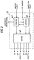
- FIG. 1 shows a fluid speed measurement arrangement employing two acoustic transducers TRD1,2 (e.g. piezo-electric devices) in a duct 10 spaced from each other by a distance L. These acoustic transducers are operable at ultrasonic frequencies.
- TRD1,2 e.g. piezo-electric devices
- the system includes a crystal oscillator 15 which provides a stable reference signal source (e.g. 32kHz). This is provided for the phase locked loop (PLL) within the broken lines and comprising a phase sensitive detector 17, a divider 18 and a voltage controlled oscillator (VCO) 19.
- PLL phase locked loop
- VCO voltage controlled oscillator
- the VCO 19 is configured to provide a fixed frequency output (e.g. 1.44MHz) controlled by its input voltage. This frequency is fed back via divider 18 (e.g. divide by 44) to give a frequency corresponding to the accurate crystal oscillator reference frequency. These frequencies are compared in detector 17 and its voltage will be adjusted if any error is present to pull the VCO into line.
- a fixed frequency output e.g. 1.44MHz
- divider 18 e.g. divide by 44
- VCO 19 provides the master clock frequency of the system.
- This master clock is made available to a timing logic block 20 which can pass this to other system blocks when required or provide control signals dependent on internal logic (or as instructed by a microprocessor/controller 31).
- a timing logic block 20 can pass this to other system blocks when required or provide control signals dependent on internal logic (or as instructed by a microprocessor/controller 31).
- each transducer is used alternatively to transmit and receive a carrier wave or burst of signals, typically pulses, each transducer will have access to transmit and receive circuitry and the timing logic will determine, under microprocessor control, when these events will occur.
- a transmit generator 21 will receive master clocks from timing block 20 as well as instructions to transmit and the transducer selected for transmission.
- the transmitter output will comprise a burst of pulses (e.g at a frequency of 180 kHz) with the phase of the pulses being inverted partway through the transmission to act as a marker and this burst will pass to either interface block 22 or 23.
- Each of blocks 22 and 23 include a transmission stage for the associated transducer and a receiving preamplification stage for handling the received signal generated as a result of passage of the ultrasonic output through the duct 10.
- the received signal is further amplified in common amplifier 24 and passed to a scanned capacitive array (SCA) 25 which, as described in more detail below, is provided with 'snapshots' of respective portions of cycles of the incoming waveforms.
- SCA scanned capacitive array
- the information built up and stored by the capacitors serves two purposes, firstly it acts as a phase memory for a reference via a filter 27 and a phase detector 29 for determining a phase change and secondly it acts as an information memory source after phase change detection for use by the microprocessor 31 via an analogue to digital(AD) converter 30.
- the microprocessor 31 uses the held information to derive additional timing information to ensure greater accuracy of time of flight to be determined, as described below.
- the phase detector 29 also receives the output of a low pass filter 28 at its other input and the two inputs allow the detector to determine when a change of phase has occurred (indicative of the returning marker).
- the signal from the capacitor array 25 is delayed with respect to the signal at the other input to the detector 29 which aids the detection of the phase change of the undelayed signal.
- the detector output causes the logic block 20 to send an inhibit or freeze signal to array 25 to prevent further signal samples being stored therebye and allows the stored values to be retained and available to the microprocessor 31.
- the microprocessor will make use of information on the number of master clock pulses that have occurred during the flight time together with additional information derived from the stored voltages on the capacitor array to determine transit time. This combined information provides increased resolution in flight time computation and the results in terms of speed or fluid flow rate, for example, can be made available to a display 32.
- the output from microcontroller 31 may also be made available for remote access, for example.
- the transmit generator 21 will be required to transmit a burst of information to alternate transducers and a suitable configuration for the generator 21 is shown in Figure 2.
- This comprises a counter 40, a control block 41 and a gating block 42.
- the timing logic block 20 of Figure 1 provides three inputs to the generator block 21. These are the master clock pulses, a transmit trigger and a direction select signal.
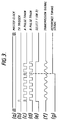
- the counter 40 receives and counts the master clock pulses (see Figure 3a) following the transmit trigger (see Figure 3b) and provides a series of pulses (see Figure 3c and 3d) for transmission via gating block 42.
- the counter 40 will provide the timing reference signal (see Figure 3g) which will be the start point from which the time of flight is calculated.
- the master clock pulses of Figure 3a are continually generated to act as a system reference source.
- the antiphase pulse trains A and B of Figure 3c and 3d are used in the drive circuitry within blocks 22 or 23 of Figure 1 as described below.
- a select signal (see Figure 3e) is also provided to select which transducer (TDR1 or TDR2) is used on this particular occasion for transmission (the other transducer being available for reception).
- the waveform for transmission (after passing through matching components within blocks 22 or 23 of Figure 1) will be as represented by Figure 3f.
- the pulse trains and the transmission signal derived therefrom each comprise a number of cycles followed by an inverted signal, this followed by further cycles.
- Figure 3c and 3d there are four pulse cycles before the inversion and then two more pulse cycles therafter.
- the system would provide an initial 16 cycles before inversion and eight cycles thereafter as determined by control 41.
- the counter 40 receives the master clocks at 1.44MHz and it counts each 8 clock pulses and provides an output thereafter to provide a divide by eight function.
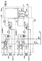
- the pulse trains of Figure 3c and 3d are produced at a rate of 180kHz, suitable for use by the ultrasonic transducers TDR1 and TDR2 after suitable matching in blocks 22 or 23. A configuration for these blocks is shown in Figure 4, somewhat simplified for the sake of clarity.
- Block 22 receives signals A1,B1 and Select 1.
- A1 and B1 are connected via resistors R1 and R2 to transistors TR1 and TR2 which have outputs to transformer T1.
- the other winding of T1 is connected to transducer TDR1.
- Capacitor C11 is connected across TDR1.
- Resistor R8 is connected to field effect transistor (FET) S1 which operates as a switch in dependence on the Select 1 input.
- FET field effect transistor
- T1, C11 and R8 act as matching network components for transmission and reception to ensure optimum operating characteristics.
- Transistors TR1 and TR2 together with diodes D1 and D2 are connected to a constant current regulator comprising transistor TR5 and resistor R5.
- Transistor TR6 provides a first amplification stage during reception of signals from TRD1 and this transistor output is connected to preamplifier stage 24a of amplifier 24.
- the preamp comprises transistors TR8 and TR9 with associated resistors R10-R12. Feedback is provided via resistor R6.
- Block 23 is identical to block 22 and comprises resistors R3,R4,R7,R9, transistors TR3,4,7, transformer T2, capacitor C12, FET S2 and diodes D3,4. This block also has access to the constant current regulator TR5/R5 and the amplifier block 24. Resistor R9, transformer T2 and capacitor C12 provide the matching network.
- TR1 and TR2 are alternately activated by signals A1 and B1 through R1 and R2. Emitter current is monitored by R5 and TR5 (common to both channels). When current reaches the conduction threshold of TR5 (which it does within a few nSec of each positive edge of the incoming signal), TR5 conducts to reduce the base drive and form a current regulation loop. Power is coupled to the transducer via the centre tapped primary winding of T1, which forms part of the matching network associated with TDR1. The constant current nature of the excitation prevents any modification of the impedance characteristics of the matching network.
- S1 is turned on by the Select 1 signal to provide a low impedance path for currents circulating in the matching network. S1 remains on during the reception period of the transmitted signal by the receiving transducer TDR2.
- the waveform for transmission is shown in Figure 3f.
- signals A2 and B2 are inactive and TR3 and TR4 are disabled.
- S2 is turned off, enabling the first amplifier transistor TR7.
- TR7, 8 and 9 thus act as a high gain amplifier with negative feedback via R7.
- the heavy negative feedback ensures a very low input impedance to the matching network, comparable with that provided by S2 during transmission.
- the matching network is maintained substantially invarient for both transmission and reception in this way. Typically phase coherence of less than 0.1 degree can be maintained with normal component tolerances.
- the channels 1 and 2 will reverse operation during the next transmission burst, with channel 2 transmitting and channel 1 receiving the ultrasonic signals under selection control.
- the system is required to determine the period between transmission and reception of the transducer signal having travelled through the duct 10 (i.e. transit time).
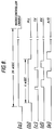
- This time period can be represented by comparison of Figure 5b and 5c waveforms.
- the number of cycles on either side of the phase change has been reduced to enable a more detailed examination of the area of the waveform adjacent the phase change to be effected.
- the waveform of Figure 5a is the master clock train (e.g. at 1.44 MHz).
- Figure 5b represents the transmitted signal and 5c represents the returning signal delayed by the period taken to travel through the duct between the transducers.
- Array 25 of Figure 1 is shown in detail in Figure 6 and comprises eight capacitors 1-8 which are sequentially scanned, each capacitor storing a voltage which represents a snapshot of the instantaneous voltage applied to it as the incoming received voltage waveform of Figure 5c progresses.
- each capacitor is connected via a common resistor R so that these form a simple RC integrating network that enables averaging of each capacitor sample voltage from one wave to the next. This averaging over a number of waves gives a filtering effect to the stored voltage. This effect can be seen from the voltage on the capacitors over several cycles.
- the first three sequencing cycles of Figure 5d show no voltage present on the capacitors 1-8, but as the returning ultrasonic signal occurs the capacitors 5-8 in the fourth cycle begin to hold a sampled voltage.
- Capacitors 1-4 do not receive a change in voltage till the fifth cycle. It can be seen that capacitors 5-8 in the fifth cycle have accrued a higher (positive) voltage and capacitors 1-4 accrue a negative voltage which will continue in subsequent cycles. Only two waves are shown prior to the phase change in this simplified waveform, but in practice there would typically be 16 wave cycles before the phase change so the averaging period would be substantially longer than shown. This gives good noise rejection with narrow receiver bandwidth (approx 4kHz).
- the input from amplifier 24 is passed via the common resistor R to the capacitors C1-C8 via switches 50 and 51.
- Switch 51 receives master clock pulses from timing block 20 of Figure 1 and switch 50 is also controlled by this block 20.
- Switch 52 is also controlled by block 20 to allow the microcontroller 31 to be able to actuate switch 51 when the receiving sequence is completed.
- the switch 51 will normally step at the master clock rate (e.g. 1.44MHz) so that, as shown in Figure 5d, each capacitor will be connected for 1/8th of the cycle period of a received waveform.
- the switch 51 will continue to rotate until inhibited by block 20 (as a result of a detected phase change).
- the phase inversion will be detected by detector 29 which comprises a limiting amplifier 53, a synchronous detector 54, a low pass filter and a comparator 56.
- the synchronous detector 54 receives inputs from the low pass filters 27 and 28.
- filter 28 receives its input directly from amplifier 24
- filter 27 receives its input from the RC network.
- the dynamic characteristic of the sequencing capacitors is equivalent to that of a resonant LC circuit and acts as a phase memory to operate as a reference input to the phase detector 29.
- the synchronous detector 54 output passes through filter 55 (see waveform of Figure 5e) and is detected by comparator 56 (see Figure 5f) to provide the detection signal for the timing block 20 of Figure 1.
- Block 20 then disconnects switch 50 from the incoming signal from amplifier 24 and connects switch 52 to the microcontroller 31 so the stored capacitor voltages can therafter be connected in turn (using switch 51) to analogue to digital converter 30 of Figure 1, via switch 50, to allow measurement of each of these voltages.
- the microprocessor 31 of Figure 1 will have knowledge from block 20 of how many master clock pulses have occurred during the period between transmission and detection of the returning phase inversion marker and this gives a timing period accurate to within 1 clock period of the master clock, which is 1/8th of the ultrasonic signal frequency.
- the time of flight accuracy would be expected to be within a usec (i.e. a millionth of a second). In practice due to slight waveform drift for example, this is more likely to be accurate to two or three clock pulses (e.g. 5 millionths of a second).
- the master clock is divided by 8 to generate the transmit signal this ensures it is in phase with the master clock.
- the master clock is also used to step switch 51 so that the first switch cycle starts at the beginning of the transmit waveform (see Figure 5b and 5d) and continues till a detected phase reversal.
- the voltages stored on each capacitor averaged over several cycles mimic the phase of the received waveform.
- the values on the capacitor array at disconnection in the sequence 1-8 will be as shown in Figure 5g.
- the voltages on the capacitors are each converted into an 8 bit value in the A/D converter 30 of figure 1.
- the phase angle of the stored waveform is computed using a single point Fourier transform, for example, on the digital voltage values and the resultant resolution is approximately 5nS, an improvement of 1000 times over that achieved using the clocks alone.
- Sine and Cosine coefficients of the reconstructed sine wave are calculated using the following equation (where vO to v7 are the digital values of the capacitor array in the range 0 to 255.
- Sine Coeff (v2 - v6) + 0.707(v1 + v3 - v5 - v7)
- Cosine Coeff (vO - v4) + 0.707(v1 + v7 - v3 - v5)
- the magnitudes and signs of the sine and cosine coefficients are determined and used to calculate which octant the cycle is in.
- the coarse count derived from the master clocks and the fine count from the above are combined in binary form. To effect this, the coarse count is decremented until its 3 least significant bits (LSBs) match the 3 most significant bits (MSBs) of the fine count. The bottom 3 bits of the coarse count are then discarded and the coarse count shifted 7 times. Finally the fine count is added to the coarse count all under microprocessor control.
- LSBs least significant bits
- MSBs most significant bits
- the combined count is now in terms of the 1.44MHz master clock x 128 giving a 184.3MHz timing resolution. This can be improved with more A/D resolution.
- 8 bit digitisation gives a resolution equivalent to approximately 1/1000th of a cycle.
- 10 bit resolution gives a resolution approximately 1/4000th of a cycle or about 1.3 nS at a 180kHz frequency.
- V (L/2t1 - L/2t2) where t1 and t2 are transit times in each direction, V is velocity and L is the length between the transducers.
- This formula can be modified where transducer delay or effective length reduction is significant.
- Volume of gas can be determined from the speed results over a given time for a given duct bore size.
- the speed of operation governed by the master clocks is sufficiently low to provide savings in cost and power consumption whilst giving equivalent resolution of 100MHz or more.
- the system can be modified to allow the transducers to operate for short periods with relatively long rest periods, which is particularly useful where battery power is required to drive the system ( e.g. in isolated locations).
- the transducers TDR1,2 are connected to blocks 22,23 and common receive amp 24 and transmit generator 21 as before.
- the phase detector 29 (with input filters, not shown) is connected to a counter 63.
- the microcontroller 31 e.g. Hitachi type 68HCO5 is selected for low voltage operation, so that the system can be powered by a single lithium cell, for example.
- the counter is used to determine the number of master clocks during the period between transmission and detection of the phase inversion marker.
- the output of counter 63 is available for bus 61 which is connected to the microcontroller 31 via control interface 62.
- a clock block 75 (e.g. 2MHz) is associated with the microcontroller and both receive inputs from timer 60.
- System control and standby timer 60 is provided to periodically enable the microcontroller and other components and at other times to put the system on standby and to provide an absolute time clock for the system.
- the clock 75 is turned on shortly before the microcontroller 31 is enabled to ensure this has stabilised before microcontroller operation commences.
- the microcontroller 31, when enabled by timer 60 is then available to carry out the system sequence of transmission, reception, conversion, calculation and display. Once the sequence is completed the clock is switched off to save power.
- the switched capacitor array 25 can have each voltage multiplexed via analogue multiplexer 78 to the A/D converter 30 which is preferably a 10 bit A/D to improve timing resolution.
- the converter output is available to the microcontroller via the control interface 62.
- a further A/D converter 70 may also receive inputs concerning battery voltage and temperature for monitoring or adjustment purposes. This is integral with controller 31 as is ROM 74, RAM 73, and electrically erasable programmable read only (EEPROM)72.
- a universal asynchronous receiver transmitter (UART)71 is provided as a serial data interface.
- a liquid crystal display (LCD) 65 is provided via driver 64.
- the driver has its own internal clock source.
- the oscillator 15, phase detector 17, divider 18 and VCO 19 are provided as before.
- the divider ratio can be set via bus 61 and the phase locked loop comprising these blocks can be enabled when required by timer 60.
- the periodic use of the PLL and other components reduces power requirements and the only system blocks requiring continuous power are the LCD 65, the oscillator 15 and timer block 60.
- the microcontroller is continuously powered although its associated clock 75 will not be powered during standby to reduce power drain.
- the timer 60 is active as is oscillator 15 which is needed as the clock input for the timer. Where a continuous display is required, LCD 65 will also be powered.
- the microcontroller 31 is enabled (see Figure 8a) for a period of 20 msec which is a sufficient to carry out transmission and detection of the ultrasonic pulses in both directions and to compute results therefrom.
- Receiving circuitry will be active immediately after the transmission in each direction (see Figure 8d).
- the voltages on the 8 capacitors in the array will be converted into digital values after reception has ceased. Two such operations will occur, one for each direction of reception (see Figure 8e).
- the PLL is active for about 4mSec with the transducers being operative at various times in this period.
- Transmission typically requires about 50mA current but because of the brief period of activity, this averages over any given second to a mere 13uA. Other periods are similarly brief, so that instead of having to cope with average power consumption of say 5mA if the system was continuously active, this has been reduced to a very much lower value, typically 100uA.
- capacitor configuration to increase resolution also reduces power requirements because higher rate clocking would increase power consumption considerable in order to seek the resolution achieved by the present configuration.
Landscapes
- Physics & Mathematics (AREA)
- General Physics & Mathematics (AREA)
- Engineering & Computer Science (AREA)
- Fluid Mechanics (AREA)
- Electromagnetism (AREA)
- Acoustics & Sound (AREA)
- Multimedia (AREA)
- Aviation & Aerospace Engineering (AREA)
- Photometry And Measurement Of Optical Pulse Characteristics (AREA)
- Measurement Of Velocity Or Position Using Acoustic Or Ultrasonic Waves (AREA)
- Investigating Or Analysing Biological Materials (AREA)
- Measuring Volume Flow (AREA)
- Arrangements For Transmission Of Measured Signals (AREA)
- Transition And Organic Metals Composition Catalysts For Addition Polymerization (AREA)
- Iron Core Of Rotating Electric Machines (AREA)
- Acyclic And Carbocyclic Compounds In Medicinal Compositions (AREA)
Applications Claiming Priority (3)
| Application Number | Priority Date | Filing Date | Title |
|---|---|---|---|
| GB8924517A GB2237639B (en) | 1989-10-31 | 1989-10-31 | Measurement system |
| GB8924517 | 1989-10-31 | ||
| EP90310990A EP0426309B1 (en) | 1989-10-31 | 1990-10-08 | Measurement system |
Related Parent Applications (1)
| Application Number | Title | Priority Date | Filing Date |
|---|---|---|---|
| EP90310990.8 Division | 1990-10-08 |
Publications (1)
| Publication Number | Publication Date |
|---|---|
| EP0670477A2 true EP0670477A2 (en) | 1995-09-06 |
Family
ID=10665476
Family Applications (2)
| Application Number | Title | Priority Date | Filing Date |
|---|---|---|---|
| EP90310990A Expired - Lifetime EP0426309B1 (en) | 1989-10-31 | 1990-10-08 | Measurement system |
| EP95107583A Withdrawn EP0670477A2 (en) | 1989-10-31 | 1990-10-08 | Measurement system |
Family Applications Before (1)
| Application Number | Title | Priority Date | Filing Date |
|---|---|---|---|
| EP90310990A Expired - Lifetime EP0426309B1 (en) | 1989-10-31 | 1990-10-08 | Measurement system |
Country Status (12)
| Country | Link |
|---|---|
| US (1) | US5178018A (ja) |
| EP (2) | EP0426309B1 (ja) |
| JP (2) | JPH07119638B2 (ja) |
| KR (1) | KR940001143B1 (ja) |
| AT (1) | ATE130934T1 (ja) |
| AU (2) | AU620738B2 (ja) |
| CA (1) | CA2028011C (ja) |
| DE (1) | DE69023884T2 (ja) |
| DK (1) | DK0426309T3 (ja) |
| ES (1) | ES2080125T3 (ja) |
| GB (2) | GB2237639B (ja) |
| HK (1) | HK1008086A1 (ja) |
Cited By (6)
| Publication number | Priority date | Publication date | Assignee | Title |
|---|---|---|---|---|
| FR2739185A1 (fr) * | 1995-09-25 | 1997-03-28 | Schlumberger Ind Sa | Procede de mesure acoustique d'un debit de fluide |
| EP1345012A3 (en) * | 2002-03-15 | 2005-05-04 | Matsushita Electric Industrial Co., Ltd. | Flow meter |
| GB2433321A (en) * | 2005-12-16 | 2007-06-20 | Landis & Gyr Ag | Ultra-sonic gas flow meter that uses a pair of transducers to find the time different for a signal to travel with the flow and against the flow |
| CN105911308A (zh) * | 2016-06-13 | 2016-08-31 | 中科同德(厦门)物联网科技有限公司 | 一种风速风向的测量方法 |
| CN107923778A (zh) * | 2015-09-23 | 2018-04-17 | 德克萨斯仪器股份有限公司 | 用于超声波流量计的交互操作的超声波流量计自动调谐 |
| CN112213518A (zh) * | 2019-07-12 | 2021-01-12 | 萨基姆通讯能源及电信联合股份公司 | 测量流体速度的方法 |
Families Citing this family (47)
| Publication number | Priority date | Publication date | Assignee | Title |
|---|---|---|---|---|
| NZ243294A (en) * | 1991-06-25 | 1995-04-27 | Commw Scient Ind Res Org | Time of flight of acoustic wave packets through fluid: reduction of higher order acoustic mode effects |
| NZ243293A (en) * | 1991-06-25 | 1995-03-28 | Commw Scient Ind Res Org | Fluid flow meter: time of travel of acoustic wave packet through fluid |
| GB9119742D0 (en) * | 1991-09-16 | 1991-10-30 | British Gas Plc | Measurement system |
| GB2276240B (en) * | 1993-03-16 | 1997-01-15 | British Gas Plc | Fluid flowmeter |
| GB2282447B (en) * | 1993-09-29 | 1997-02-12 | Siemens Measurements Ltd | Improvements in or relating to gas meters |
| JPH07248517A (ja) * | 1994-03-10 | 1995-09-26 | Nikon Corp | 振動検出装置 |
| FR2721360B1 (fr) * | 1994-06-17 | 1996-08-02 | Schlumberger Ind Sa | Oscillateur fluidique et procédé de mesure d'une quantité volumique de fluide s'écoulant dans un tel oscillateur fluidique. |
| JPH08122117A (ja) * | 1994-10-19 | 1996-05-17 | Matsushita Electric Ind Co Ltd | 流量計測装置 |
| FR2734361B1 (fr) | 1995-05-17 | 1997-07-18 | Schlumberger Ind Sa | Dispositif pour la mesure de la vitesse d'ecoulement d'un fluide par ultrasons |
| DE19522697A1 (de) * | 1995-06-22 | 1997-01-09 | Sick Optik Elektronik Erwin | Verfahren und Schaltungsanordnung zur Messung der Strömungsgeschwindigkeit mittels akustischer Laufzeitdifferenzen |
| FR2748816B1 (fr) * | 1996-05-17 | 1998-07-31 | Schlumberger Ind Sa | Dispositif ultrasonore de mesure de la vitesse d'ecoulement d'un fluide |
| FR2749652B1 (fr) * | 1996-06-07 | 1998-08-21 | Schlumberger Ind Sa | Procede de mesure du temps de propagation d'un signal acoustique dans un fluide par passage a zero dudit signal acoustique |
| US5777238A (en) * | 1996-06-12 | 1998-07-07 | Welch Allyn, Inc. | Driver-receiver apparatus for use with ultrasonic flowmeters |
| US6112601A (en) * | 1996-07-01 | 2000-09-05 | Schlumberger Industries, S.A. | Method and apparatus for measuring the flow rate of a flowing fluid |
| FR2750495B1 (fr) * | 1996-07-01 | 1998-08-21 | Schlumberger Ind Sa | Procede et dispositif de mesure d'un debit de fluide en ecoulement |
| US5668326A (en) * | 1996-10-04 | 1997-09-16 | Dieterich Technology Holding Corp. | Method and apparatus for detecting and aligning a signal |
| US5814737A (en) * | 1996-10-04 | 1998-09-29 | Dieterich Technology Holding Corp. | Apparatus and method of detecting an ultrasonic signal |
| US6062091A (en) * | 1997-04-22 | 2000-05-16 | Baumoel; Joseph | Method and apparatus for determining ultrasonic pulse arrival in fluid using phase correlation |
| US6314055B1 (en) | 1998-10-16 | 2001-11-06 | Intersense, Inc. | Range measuring system |
| FR2787880B1 (fr) * | 1998-12-29 | 2001-03-02 | Schlumberger Ind Sa | Dispositif et procede de mesure ultrasonore de debit de fluide comportant un convertisseur analogique numerique sigma-delta passe bande |
| JP2000206099A (ja) * | 1999-01-11 | 2000-07-28 | Ngk Spark Plug Co Ltd | ガス濃度センサ |
| WO2001009636A1 (en) * | 1999-07-28 | 2001-02-08 | Intersense, Inc. | Range measuring system |
| AUPQ480199A0 (en) | 1999-12-22 | 2000-02-03 | AGL Consultancy Pty. Limited | Timed window ultrasonic gas meter with nose cone |
| JP4886120B2 (ja) * | 2001-05-16 | 2012-02-29 | 東京計器株式会社 | 超音波流速計 |
| DE10163566A1 (de) * | 2001-12-21 | 2003-07-10 | Flowtec Ag | Pulsgenerator |
| US6925891B2 (en) | 2002-04-30 | 2005-08-09 | Matsushita Electric Industrial Co., Ltd. | Ultrasonic flowmeter and method of measuring flow volume |
| JP3669580B2 (ja) * | 2002-05-24 | 2005-07-06 | 学校法人慶應義塾 | 超音波流速分布及び流量計 |
| AU2003902318A0 (en) * | 2003-05-14 | 2003-05-29 | Vision Fire And Security Pty Ltd | Improved Sensing Apparatus And Method |
| RU2284015C2 (ru) * | 2004-04-01 | 2006-09-20 | Московский государственный горный университет (МГГУ) | Способ измерения расхода потока и устройство для его осуществления |
| DE102004023147A1 (de) | 2004-05-07 | 2005-11-24 | Endress + Hauser Flowtec Ag, Reinach | Vorrichtung zur Bestimmung und/oder Überwachung des Volumen- und/oder Massendurchflusses eines Mediums |
| GB0516752D0 (en) * | 2005-08-13 | 2005-09-21 | Flownetix Ltd | A method for ultra low power transit time ultrasonic flow measurement |
| WO2007020378A1 (en) * | 2005-08-13 | 2007-02-22 | Flownetix Limited | Low power ultrasonic flow measurement |
| JP4788235B2 (ja) * | 2005-08-16 | 2011-10-05 | パナソニック株式会社 | 流体の流れ計測装置 |
| SE529249C2 (sv) * | 2005-10-14 | 2007-06-12 | Hexagon Metrology Ab | Förfarande vid signalbehandling vid kapacitiva mätskalor |
| RU2348904C1 (ru) * | 2007-08-06 | 2009-03-10 | Общество с ограниченной ответственностью Научно-производственный центр "Ультразвуковые технологии" | Способ акустического измерения расхода текучих сред |
| RU2367912C1 (ru) * | 2008-05-12 | 2009-09-20 | Закрытое Акционерное Общество "Когерент" | Устройство для определения объемного расхода контролируемой среды в трубопроводе |
| US8695435B2 (en) | 2008-05-12 | 2014-04-15 | Closed Corporation Coherent | Method of measuring a volume flow rate of a controlled medium in a pipeline |
| US20110119007A1 (en) * | 2009-11-18 | 2011-05-19 | Avago Technologies Wireless Ip (Singapore) Pte. Ltd. | Method and system for determining the time-of-flight of a signal |
| EP2522276A1 (en) | 2011-05-13 | 2012-11-14 | General Electric Company | Airway adapter and gas analyzer for measuring oxygen concentration of a respiratory gas |
| CN102389593B (zh) * | 2011-07-08 | 2013-12-25 | 重庆市澳凯龙医疗器械研究有限公司 | 差分流量信号处理装置及方法 |
| EP2581715A1 (en) | 2011-10-13 | 2013-04-17 | Miitors ApS | Ultrasonic flow meter |
| GB2549717B (en) * | 2016-04-25 | 2018-09-05 | Sentronics Ltd | Flow meter |
| DE102017011861B4 (de) * | 2017-12-01 | 2022-09-29 | Diehl Metering Gmbh | Verfahren zur Bestimmung der Laufzeit eines Ultraschallsignals in einem strömenden Medium sowie Ultraschalldurchflussmesser |
| RU2676225C1 (ru) * | 2018-02-07 | 2018-12-26 | Юрий Александрович Борисов | Контрольно-проверочный комплекс для проверки доплеровских измерителей скорости и сноса |
| JP7189048B2 (ja) * | 2019-02-25 | 2022-12-13 | アズビル株式会社 | 超音波流量計および出力インピーダンス設定方法 |
| US12018965B2 (en) | 2022-03-28 | 2024-06-25 | Defiant Engineering Llc | Axial LiDAR doppler analyzer |
| DE102022117248A1 (de) * | 2022-07-11 | 2024-01-11 | Esters-Elektronik GmbH | Verfahren und Fluidistor zur Bestimmung einer Durchflussmenge oder eines Maßes dafür eines durch eine Strömungsleitung strömenden Fluids, Verwendung und Fluid-Bereitstellungs-Einheit |
Family Cites Families (12)
| Publication number | Priority date | Publication date | Assignee | Title |
|---|---|---|---|---|
| FR2454101A1 (fr) * | 1979-04-11 | 1980-11-07 | Onera (Off Nat Aerospatiale) | Appareil de mesure de la vitesse d'une veine liquide par ultra-sons |
| JPS56132521A (en) * | 1980-03-19 | 1981-10-16 | Yokogawa Hokushin Electric Corp | Ultrasonic flowmeter |
| DE3025788C2 (de) * | 1980-07-08 | 1985-07-04 | Danfoss A/S, Nordborg | Ultraschall-Meßgerät |
| US4345479A (en) * | 1981-01-13 | 1982-08-24 | The Perkin-Elmer Corporation | Flowmeter system with synchronous clock for generation of timing signals |
| GB2131173B (en) * | 1982-11-30 | 1986-06-18 | Bestobell Sparling | Fluid flow monitoring |
| GB2139755B (en) * | 1983-05-11 | 1987-03-04 | British Gas Corp | Ultrasonic flowmeter |
| GB8430217D0 (en) * | 1984-11-30 | 1985-01-09 | Redding R J | Electronic gas meter |
| US4633719A (en) * | 1985-03-27 | 1987-01-06 | Badger Meter, Inc. | Digital flow meter circuit and method for measuring flow |
| GB2187552B (en) * | 1986-03-05 | 1990-07-11 | Gen Electric Plc | Apparatus for monitoring movement of a fluid |
| GB2205645A (en) * | 1987-06-12 | 1988-12-14 | Milan Herman Miessler | Fluid flow measurement |
| US4787252A (en) * | 1987-09-30 | 1988-11-29 | Panametrics, Inc. | Differential correlation analyzer |
| GB8813640D0 (en) * | 1988-06-09 | 1988-07-13 | Gill M J | Speed measurement device |
-
1989
- 1989-10-31 GB GB8924517A patent/GB2237639B/en not_active Expired - Fee Related
-
1990
- 1990-10-08 DK DK90310990.8T patent/DK0426309T3/da active
- 1990-10-08 EP EP90310990A patent/EP0426309B1/en not_active Expired - Lifetime
- 1990-10-08 EP EP95107583A patent/EP0670477A2/en not_active Withdrawn
- 1990-10-08 DE DE69023884T patent/DE69023884T2/de not_active Expired - Fee Related
- 1990-10-08 ES ES90310990T patent/ES2080125T3/es not_active Expired - Lifetime
- 1990-10-08 AT AT90310990T patent/ATE130934T1/de not_active IP Right Cessation
- 1990-10-11 US US07/596,011 patent/US5178018A/en not_active Expired - Lifetime
- 1990-10-18 AU AU64755/90A patent/AU620738B2/en not_active Ceased
- 1990-10-19 CA CA002028011A patent/CA2028011C/en not_active Expired - Fee Related
- 1990-10-31 JP JP2295182A patent/JPH07119638B2/ja not_active Expired - Lifetime
- 1990-10-31 KR KR1019900017685A patent/KR940001143B1/ko not_active Expired - Fee Related
-
1991
- 1991-11-22 AU AU88079/91A patent/AU640538B2/en not_active Ceased
-
1993
- 1993-06-10 GB GB9312017A patent/GB2266373B/en not_active Expired - Fee Related
-
1995
- 1995-06-15 JP JP7148878A patent/JP2777084B2/ja not_active Expired - Lifetime
-
1998
- 1998-06-27 HK HK98107266A patent/HK1008086A1/xx not_active IP Right Cessation
Cited By (16)
| Publication number | Priority date | Publication date | Assignee | Title |
|---|---|---|---|---|
| FR2739185A1 (fr) * | 1995-09-25 | 1997-03-28 | Schlumberger Ind Sa | Procede de mesure acoustique d'un debit de fluide |
| WO1997012248A1 (fr) * | 1995-09-25 | 1997-04-03 | Schlumberger Industries S.A. | Procede de mesure acoustique d'un debit de fluide |
| RU2182315C2 (ru) * | 1995-09-25 | 2002-05-10 | Шлюмберже Эндюстри С.А. | Способ акустического измерения расхода текучей среды |
| EP1345012A3 (en) * | 2002-03-15 | 2005-05-04 | Matsushita Electric Industrial Co., Ltd. | Flow meter |
| KR100776111B1 (ko) * | 2002-03-15 | 2007-11-16 | 마츠시타 덴끼 산교 가부시키가이샤 | 유량 계측 장치 |
| GB2433321A (en) * | 2005-12-16 | 2007-06-20 | Landis & Gyr Ag | Ultra-sonic gas flow meter that uses a pair of transducers to find the time different for a signal to travel with the flow and against the flow |
| GB2433321B (en) * | 2005-12-16 | 2010-06-02 | Landis & Gyr Ag | A gas meter |
| CN107923778A (zh) * | 2015-09-23 | 2018-04-17 | 德克萨斯仪器股份有限公司 | 用于超声波流量计的交互操作的超声波流量计自动调谐 |
| EP3353505A4 (en) * | 2015-09-23 | 2018-10-24 | Texas Instruments Incorporated | Ultrasonic flow meter auto-tuning for reciprocal operation of the meter |
| US10495502B2 (en) | 2015-09-23 | 2019-12-03 | Texas Instruments Incorporated | Ultrasonic flow meter auto-tuning for reciprocal operation of the meter |
| CN105911308A (zh) * | 2016-06-13 | 2016-08-31 | 中科同德(厦门)物联网科技有限公司 | 一种风速风向的测量方法 |
| CN112213518A (zh) * | 2019-07-12 | 2021-01-12 | 萨基姆通讯能源及电信联合股份公司 | 测量流体速度的方法 |
| EP3764104A1 (fr) * | 2019-07-12 | 2021-01-13 | Sagemcom Energy & Telecom SAS | Procede de mesure de la vitesse d'un fluide, compteur de fluide à ultrason, programme d'ordinateur et moyens de stockage |
| FR3098599A1 (fr) * | 2019-07-12 | 2021-01-15 | Sagemcom Energy & Telecom Sas | Procédé de mesure de la vitesse d’un fluide |
| CN112213518B (zh) * | 2019-07-12 | 2023-06-27 | 萨基姆通讯能源及电信联合股份公司 | 测量流体速度的方法 |
| US11740112B2 (en) | 2019-07-12 | 2023-08-29 | Sagemcom Energy & Telecom Sas | Method of measuring the speed of a fluid |
Also Published As
| Publication number | Publication date |
|---|---|
| DK0426309T3 (da) | 1995-12-27 |
| AU620738B2 (en) | 1992-02-20 |
| AU6475590A (en) | 1991-05-09 |
| GB2266373B (en) | 1994-07-06 |
| JPH07119638B2 (ja) | 1995-12-20 |
| KR910008387A (ko) | 1991-05-31 |
| DE69023884T2 (de) | 1996-04-25 |
| JPH08170926A (ja) | 1996-07-02 |
| GB9312017D0 (en) | 1993-07-28 |
| AU640538B2 (en) | 1993-08-26 |
| JP2777084B2 (ja) | 1998-07-16 |
| GB2237639A (en) | 1991-05-08 |
| US5178018A (en) | 1993-01-12 |
| GB2266373A (en) | 1993-10-27 |
| EP0426309A2 (en) | 1991-05-08 |
| CA2028011C (en) | 2000-02-01 |
| ES2080125T3 (es) | 1996-02-01 |
| DE69023884D1 (de) | 1996-01-11 |
| ATE130934T1 (de) | 1995-12-15 |
| CA2028011A1 (en) | 1991-05-01 |
| JPH03180767A (ja) | 1991-08-06 |
| GB8924517D0 (en) | 1989-12-20 |
| AU8807991A (en) | 1992-01-16 |
| KR940001143B1 (ko) | 1994-02-14 |
| EP0426309B1 (en) | 1995-11-29 |
| HK1008086A1 (en) | 1999-04-30 |
| GB2237639B (en) | 1994-07-06 |
| EP0426309A3 (en) | 1993-03-03 |
Similar Documents
| Publication | Publication Date | Title |
|---|---|---|
| EP0670477A2 (en) | Measurement system | |
| CA1157935A (en) | Ultrasonic flowmeter | |
| US6305233B1 (en) | Digital speed determination in ultrasonic flow measurements | |
| US5035147A (en) | Method and system for digital measurement of acoustic burst travel time in a fluid medium | |
| KR920010025B1 (ko) | 유속측정방법 및 그 장치 | |
| CA1216656A (en) | Method and apparatus for measuring fluid flow | |
| RU2186399C2 (ru) | Ультразвуковое устройство для измерения скорости потока | |
| US6575044B1 (en) | Transit-time flow sensor combining high resolution and wide dynamic range | |
| JPS5836528A (ja) | 超音波パルスドツプラ血流測定装置 | |
| US4446744A (en) | Ultrasonic flowmeter | |
| US4345479A (en) | Flowmeter system with synchronous clock for generation of timing signals | |
| US4321835A (en) | Apparatus for measuring the flow velocity of a fluid | |
| US4372168A (en) | Flowmeter | |
| JP3251378B2 (ja) | 気体用超音波流量計 | |
| CN113985062A (zh) | 一种低流速高精度多普勒声学双向流速仪 | |
| JP3651110B2 (ja) | 超音波流速計 | |
| JPS626811B2 (ja) | ||
| SU734507A1 (ru) | Одноканальный ультразвуковой расходомер | |
| SU191155A1 (ru) | Ультразвуковой расходомер | |
| SU1137306A1 (ru) | Ультразвуковой фазовый цифровой расходомер | |
| SU1690681A1 (ru) | Устройство дл формировани импульсов дыхательных движений | |
| SU690310A1 (ru) | Цифровой акустический уровнемер | |
| SU972223A1 (ru) | Импульсный одноканальный ультразвуковой расходомер | |
| SU657334A1 (ru) | Автоциркул ционный измеритель скорости ультразвука | |
| RU2210062C1 (ru) | Ультразвуковой расходомер |
Legal Events
| Date | Code | Title | Description |
|---|---|---|---|
| PUAI | Public reference made under article 153(3) epc to a published international application that has entered the european phase |
Free format text: ORIGINAL CODE: 0009012 |
|
| 17P | Request for examination filed |
Effective date: 19950518 |
|
| AC | Divisional application: reference to earlier application |
Ref document number: 426309 Country of ref document: EP |
|
| AK | Designated contracting states |
Kind code of ref document: A2 Designated state(s): AT BE DE DK ES FR GB IT NL SE |
|
| STAA | Information on the status of an ep patent application or granted ep patent |
Free format text: STATUS: THE APPLICATION IS DEEMED TO BE WITHDRAWN |
|
| 18D | Application deemed to be withdrawn |
Effective date: 19960503 |