EP0670276A1 - Conveying device for products, especially for fruits, adapted for sorting the said products according the predetermined features of selection - Google Patents
Conveying device for products, especially for fruits, adapted for sorting the said products according the predetermined features of selection Download PDFInfo
- Publication number
- EP0670276A1 EP0670276A1 EP95200464A EP95200464A EP0670276A1 EP 0670276 A1 EP0670276 A1 EP 0670276A1 EP 95200464 A EP95200464 A EP 95200464A EP 95200464 A EP95200464 A EP 95200464A EP 0670276 A1 EP0670276 A1 EP 0670276A1
- Authority
- EP
- European Patent Office
- Prior art keywords
- conveyor
- conveying
- rollers
- conveying device
- hands
- Prior art date
- Legal status (The legal status is an assumption and is not a legal conclusion. Google has not performed a legal analysis and makes no representation as to the accuracy of the status listed.)
- Granted
Links
Images


Classifications
-
- B—PERFORMING OPERATIONS; TRANSPORTING
- B65—CONVEYING; PACKING; STORING; HANDLING THIN OR FILAMENTARY MATERIAL
- B65G—TRANSPORT OR STORAGE DEVICES, e.g. CONVEYORS FOR LOADING OR TIPPING, SHOP CONVEYOR SYSTEMS OR PNEUMATIC TUBE CONVEYORS
- B65G47/00—Article or material-handling devices associated with conveyors; Methods employing such devices
- B65G47/74—Feeding, transfer, or discharging devices of particular kinds or types
- B65G47/94—Devices for flexing or tilting travelling structures; Throw-off carriages
- B65G47/96—Devices for tilting links or platform
- B65G47/962—Devices for tilting links or platform tilting about an axis substantially parallel to the conveying direction
- B65G47/965—Devices for tilting links or platform tilting about an axis substantially parallel to the conveying direction tilting about a sided-axis, i.e. the axis is not located near the center-line of the load-carrier
-
- B—PERFORMING OPERATIONS; TRANSPORTING
- B07—SEPARATING SOLIDS FROM SOLIDS; SORTING
- B07C—POSTAL SORTING; SORTING INDIVIDUAL ARTICLES, OR BULK MATERIAL FIT TO BE SORTED PIECE-MEAL, e.g. BY PICKING
- B07C5/00—Sorting according to a characteristic or feature of the articles or material being sorted, e.g. by control effected by devices which detect or measure such characteristic or feature; Sorting by manually actuated devices, e.g. switches
- B07C5/16—Sorting according to weight
- B07C5/18—Sorting according to weight using a single stationary weighing mechanism
-
- B—PERFORMING OPERATIONS; TRANSPORTING
- B65—CONVEYING; PACKING; STORING; HANDLING THIN OR FILAMENTARY MATERIAL
- B65G—TRANSPORT OR STORAGE DEVICES, e.g. CONVEYORS FOR LOADING OR TIPPING, SHOP CONVEYOR SYSTEMS OR PNEUMATIC TUBE CONVEYORS
- B65G47/00—Article or material-handling devices associated with conveyors; Methods employing such devices
- B65G47/52—Devices for transferring articles or materials between conveyors i.e. discharging or feeding devices
-
- B—PERFORMING OPERATIONS; TRANSPORTING
- B65—CONVEYING; PACKING; STORING; HANDLING THIN OR FILAMENTARY MATERIAL
- B65G—TRANSPORT OR STORAGE DEVICES, e.g. CONVEYORS FOR LOADING OR TIPPING, SHOP CONVEYOR SYSTEMS OR PNEUMATIC TUBE CONVEYORS
- B65G2201/00—Indexing codes relating to handling devices, e.g. conveyors, characterised by the type of product or load being conveyed or handled
- B65G2201/02—Articles
- B65G2201/0202—Agricultural and processed food products
- B65G2201/0211—Fruits and vegetables
-
- B—PERFORMING OPERATIONS; TRANSPORTING
- B65—CONVEYING; PACKING; STORING; HANDLING THIN OR FILAMENTARY MATERIAL
- B65G—TRANSPORT OR STORAGE DEVICES, e.g. CONVEYORS FOR LOADING OR TIPPING, SHOP CONVEYOR SYSTEMS OR PNEUMATIC TUBE CONVEYORS
- B65G2207/00—Indexing codes relating to constructional details, configuration and additional features of a handling device, e.g. Conveyors
- B65G2207/42—Soft elements to prevent damage to articles, e.g. bristles, foam
-
- Y—GENERAL TAGGING OF NEW TECHNOLOGICAL DEVELOPMENTS; GENERAL TAGGING OF CROSS-SECTIONAL TECHNOLOGIES SPANNING OVER SEVERAL SECTIONS OF THE IPC; TECHNICAL SUBJECTS COVERED BY FORMER USPC CROSS-REFERENCE ART COLLECTIONS [XRACs] AND DIGESTS
- Y10—TECHNICAL SUBJECTS COVERED BY FORMER USPC
- Y10S—TECHNICAL SUBJECTS COVERED BY FORMER USPC CROSS-REFERENCE ART COLLECTIONS [XRACs] AND DIGESTS
- Y10S209/00—Classifying, separating, and assorting solids
- Y10S209/912—Endless feed conveyor with means for holding each item individually
Definitions
- the invention relates to a device for conveying products, in particular fruit, suitable for sorting said products according to predetermined selection criteria, such as weight, external appearance, etc.
- This invention relates more particularly to conveying devices comprising several supports of different types along the conveyor line, between which the fruits are transferred.
- a first type of conveying device thus designed is described in particular in US Patents 5,197,585 and US 4,830,195, and comprises a fruit loading zone consisting of a conveyor comprising a first type of support, and a second zone of sorting and unloading, consisting of at least one conveyor comprising a second type of support, said conveyors being arranged in the extension of one another.
- the major drawback of these conveying devices lies in the fact that, during the transfer of the fruits between the two conveyors, these fruits drop from a height which, while being relatively low, frequently causes the talage of the latter.
- a second type of conveyor device described in particular in patent EP 540,126 comprises a single conveyor provided with multifunctional fruit support means, comprising support members capable of retracting or supporting the fruit depending on the operation carried out ( loading, colorimetric examination, weighing, unloading ).
- Such devices overcome the aforementioned drawback because the fruits do not undergo impacts during the relative movements of the support members.
- they require very complex and therefore relatively expensive means of support, and of relatively high fragility.
- the costs of The maintenance of such conveyors is high due in particular to the complexity and the number of supports to be cleaned regularly so as not to distort the measurements (weighing, etc.).
- the present invention aims to overcome the aforementioned drawbacks of known devices and has the essential objective of providing a conveying device, on the one hand provided with fruit-supporting bodies of simple design and, on the other hand, ensuring all the operations loading, selection, unloading ... of fruits without risk of hitting them.
- Another objective of the invention is to provide a conveying device which can carry out, in addition to other selection operations, a weight calibration of the fruits.
- the first conveyor extends at the level of the loading zone according to an inclined ramp, and comprises a rolling surface of the rollers able to generate a rotation of said rollers around their axis.
- rollers are thus driven in rotation at the unloading zone, either by simple friction on the rolling surface, or by mechanically using a running surface, such as a belt, caused to run. In known manner, such a rotation has the effect of ensuring a good distribution of the fruits between the rollers.
- the first conveyor has a portion of horizontal path upstream of the transfer zone, equipped with means for analyzing the external appearance of the products, said conveyor comprising at this level analysis area, a rolling surface of the rollers capable of generating a rotation of said rollers about their axis.
- This third conveyor makes it possible to carry out a weight calibration of the products, by means of carriages which temporarily replace the conveying hands to provide support for said products, and then retracts once the weighing has been carried out, the transfers always being carried out without product is not subjected to shocks.
- the conveyor device comprises an endless conveyor belt disposed laterally on the side of the second conveyor, in the unloading zone, so as to firstly receive the discharged products and ensure their transfer to storage areas and, on the other hand, to absorb the fall of the end of the conveying hands, said strip comprising drive means capable of running it at substantially the same speed as the speed of advancement of the second conveyor.
- Such a conveyor belt in addition to the fact that it absorbs the fall of the conveying hands, has the role of preventing the fruit from becoming talented during unloading.
- the device advantageously comprises brush rollers driven in rotation about horizontal axes parallel to the direction of advance of the conveyors, said brush rollers being interposed between the conveyor belt. and storage areas. Indeed, such brush rollers have the effect of slowing the speed of the fruit arriving in the storage areas.
- the second conveyor advantageously comprises two conveyor lines composed of conveyor hands arranged on either side of a single endless chain, the first conveyor also comprising two conveyor lines each equipped with a plurality of rollers carried by an endless chain, and arranged to cooperate each with one of the conveyor lines of the second conveyor.
- the first conveyor then comprises, advantageously, at the loading area, a central separation piece disposed between the rollers of each conveyor line, so as to guide the products towards one or the another line.
- the first conveyor comprises a downstream end gear
- the second conveyor comprises a upstream end gear, mounted on the same transverse rotation shaft.
- the locking system comprises a latch comprising a hook articulated on the support and arranged to cooperate with a locking pin mounted on the conveying hand, and elastic means for biasing the hook towards its locking position, said hook and pin being arranged to cooperate, after tilting of the conveying hand, under the effect of a reverse tilting obtained by gravity upon the return of said conveying hand towards the transfer zone.
- This device is mainly divided into a zone for loading fruit, for example coming in bulk in a stream of water, an optical analysis zone, a transfer zone, a weighing zone and an unloading zone.
- the fruits are transported by a first conveyor, then transferred to a second conveyor in the transfer zone, this second conveyor ensuring their transport to the unloading zone.
- a third intermediate conveyor interposed on the path of the second conveyor, temporarily takes charge of the fruits in order to ensure their weighing.
- each of the conveyors has two conveyor lines.
- the first conveyor is composed of two separate and identical conveyor lines, distributed symmetrically on either side of a longitudinal plane of symmetry.
- Each of these conveyor lines comprises a loading zone, extending along an inclined ramp 1 and an optical analysis zone 2 arranged on a portion of horizontal path.
- Each conveyor line comprises an endless chain 3 supported by a profile 4 and meshed around two gears 5, 6.
- These conveyor lines are equipped with a plurality of rollers such as 7, adapted to define two by two of the housings for the fruits, mounted free in rotation around a rotation axis 8 integral with the endless chain and extending transversely with respect to it.
- Each of the rollers 7 comprises a central sleeve 9 mounted on the axis of rotation 8 and vertical disks, such as 10, 11, spaced apart, extending radially around the central sleeve 9. These disks 10, 11 also have different diameters adapted so that each roller 7 has a concave biconical external shape.
- the edges of these discs 10, 11 are machined so as to delimit a support surface of concave shape.
- each conveyor line of the first conveyor comprises, at the loading area 1, a rolling surface 12, fixed as shown in the figures, or movable such as a belt, capable of causing the rollers 7 to rotate. around their axis of rotation.
- the first conveyor comprises, conventionally, in the optical analysis zone 2, means for driving in rotation the rollers 7 (not shown) such as rolling surface, belt, etc. capable of generating a rotation of said rollers in line with optical analysis means 14 of any type known per se, such as a camera, etc.
- the second conveyor comprises, for its part, two conveyor lines each equipped with conveyor hands 15 arranged transversely on either side of a single endless chain 16 supported by a profile 17 extending in the longitudinal plane of symmetry of the conveying device.
- the endless chain 16 is meshed around two toothed wheels 18, 19: a toothed wheel 18 disposed at the downstream end of the conveying device, and a toothed wheel 19 mounted on the shaft 20 for driving the rotation of the downstream toothed wheels 5 of the first conveyor.
- Each conveying hand 15 is mounted articulated on a support 21 secured to the endless chain 16, said support and conveying hand being provided with locking means capable of holding each hand in a conveying position where it can bear fruit, and to allow the pivoting of this hand to a position for unloading the fruit.
- each conveying hand 15 comprises a central transverse bar 22 of concave shape, on either side of which extend orthogonally a plurality of fingers such as 23 arranged opposite one another and curved upwards , so as to give said hand an elongated bowl shape in a transverse direction relative to the endless chain 16, capable of accommodating a fruit.
- each conveying hand 15 is arranged so as to be interposed between two rollers 7 in line with the transfer zone, the fingers 23, in the example of five in number, being arranged to frame the discs 10 , 11 of said rollers.
- the central bar 22 has a section in the form of an inverted U, the two wings of which extend the core at the level of the end of attachment to the support 21, so as to form a yoke housing a horizontal locking axis 24.
- the two wings of this U are pierced, at a distance from the aforementioned end, with two facing holes for the housing of the axis 25 of articulation of the conveying hand 15 on the support 21.
- This support 21 has, meanwhile, seen from above, the shape of a T, each wing of which is secured to the endless chain 16.
- the branch of this T has, for its part, an end 26 longitudinally comprising a portion in inverted V shape, supporting the end of the central bar 22, respectively in its two conveying and unloading positions.
- This end 26 of the support 21 is arranged to be capped by the transverse bar 22, and includes a sleeve 27 capable of housing the articulation axis 25.
- the central bar 22 is provided with two orifices provided in the core of said bar and each capable of accommodating a shoe 28, 29 bearing on the end 26 of the support 21 respectively in the conveying and unloading positions. of the conveying hand.
- the locking means comprise, for their part, a latch system comprising a pivoting part 30 articulated on the support 21 and provided with a hook 31 arranged to cooperate with the locking pin 24 of the conveying hand.
- this latch system includes a pad 32 of elastomeric material carried by the support and arranged to urge the pivoting part 30 towards its locking position.
- the locking means comprise, finally, for each conveyor line of the second conveyor, a support member 33 (shown in FIG. 6) consisting of a vertical disc interposed on the return path of said conveyor, and arranged to come in tangential contact with each conveying hand 15, disposed in its inverted position, so as to ensure the locking of the latter.
- the second conveyor further comprises safety members capable of preventing the tilting of each conveying hand between the transfer zone and the unloading zone in the event of a deficiency in the locking means.
- These safety members comprise, firstly, for each conveyor line, a disc 34 carried by the rotation shaft 20 between the toothed wheels 5, 19 of the first and second conveyors, said disc being arranged to come into tangential contact under each conveying hand 15, and having a section provided with notches for the passage of the rollers 7.
- These safety members further comprise a lateral slide 35, if necessary, for supporting the end of the conveying hands, extending longitudinally between the transfer zone and the unloading zone.
- the third conveyor arranged between the transfer zone and the unloading zone, comprises two conveyor lines each interposed on the path of a conveyor line of the second conveyor.
- Each conveyor line is equipped with carriages 40 comprising spaced vertical support plates such as 41, 42, connected at their lower end by crosspieces 43 and having different heights so that said carriages have a transverse upper support face concave.
- each of these plates 41, 42 has a central notch 41a, 42a and has an upper slice extending upwards, on either side of said notch, so as to form an upper face for supporting the fruits. having the shape of a bowl.
- these plates are four in number: two lateral plates such as 41 of the same height, and two central plates such as 42 of the same height, less than that of the central plates 42, said lateral plates 41 and central 42 being longitudinally offset and each provided with a notch 44, 45 formed respectively at the right of their rear end (central plates) and front (side plates), and forming two transverse grooves.
- the support means of these carriages 40 comprise, in the first place, a transverse traction axis 46 of diameter less than the height of the notches 44, 45, secured to the endless chain 36 towards one of its ends and extending to the inside the front groove.
- These support means further comprise two lateral connecting rods such as 47, arranged on either side of the carriage 40 and articulated respectively on the transverse axis 46 and on a lug 48 projecting relative to the external face of the lateral plates 41, towards the rear end of the latter.
- carriages 40 are arranged one behind the other so that the rear groove (notches 45) of one carriage is in alignment with the front groove (notches 44) of the next carriage, the rear area of the first carriage thus being supported by the traction axis 46 of the following carriage.
- each plate 41, 42 is provided with a lower bearing heel such as 49, 50, disposed towards the front end of the side plates 41, and towards the rear end of the central plates 42.
- Each of these carriages 40 is arranged to accommodate a conveying hand 15, the central bar 22 extending in the notches 41a, 42a, and the fingers 23 being arranged on either side of the plates 41, 42.
- the height of the plates 41, 42 is adapted so that the fruit is carried by the carriage 40, and not by the conveying hand 15 when said carriage and hand are nested one inside the other.
- the third conveyor finally comprises conventional weighing means, comprising a slide 51 provided with an upper face for sliding the support heels 49, 50 of the carriages, equipped with a balance 52 comprising four weighing zones such as 53 arranged to be each plumb with one of said support heels.
- the unloading area to which the fruits are brought, carried by the conveying hands comprises compartments such as 54, 55 arranged one after the other laterally on either side of the conveying lines.
- means for triggering the locking means are associated with each of these lockers.
- These triggering means comprise a cam 57 provided with an access ramp, an active planar face and an exit ramp, and pivotally mounted around a transverse axis on a fixed vertical plate 58 disposed above of the conveying line, in alignment, transversely, from the start of each rack 54, 55.
- This cam 57 is articulated on the rod of a jack 59 able to rotate it between a high position where it freely lets the pivoting part 30 now locked the conveying hand 15, and a low position where it is placed on the path of this pivoting part and or it causes its pivoting and consequently the fall of the conveying hand 15.
- each cam 57 there is a support pad 62 arranged under the support 21 of the conveying hands, towards the end of the latter, and intended to avoid possible deformation of this support.
- This shoe 62 extends, moreover, longitudinally on either side of each trigger zone so as to ensure the stabilization of the conveyor lines of the second conveyor in the event that one of these lines is found to be transporting much more fruit than the other.
- This cam is associated with a rotary electromagnet 66 capable of rotating it between a position (shown in solid lines in FIG. 11) where it is offset laterally relative to the path of the hook 31 and where it lets the pivoting part 30, and a position (shown in dotted lines in FIG. 11) where it is located on the path of the hook 31 and where it causes it to pivot.
- the unloading zone is equipped, for each conveyor line, with a longitudinal conveyor belt 60 capable of traveling at the same speed as said conveyor line, and interposed between the latter and the compartments 54, 55.
- This conveyor belt 60 is intended to absorb the fall of the conveying hands 15 and of the fruit.
- each rack is equipped with a brush roller 61 intended to brake the fruit, rotatably mounted around a horizontal longitudinal axis and arranged parallel to the conveyor belt 60.
- a flap with a horizontal axis shown diagrammatically at 63, is disposed above the conveyor belt 60, in the extension of each partition between the compartments 54, 55.
- This flap 63 arranged to be lifted when a fruit is present on the conveyor belt 60 at the right of a partition, presence signifying that the previous locker is filled, is intended to constitute a detection member capable of commanding an emergency stop.
Landscapes
- Engineering & Computer Science (AREA)
- Mechanical Engineering (AREA)
- Sorting Of Articles (AREA)
- Discharge Of Articles From Conveyors (AREA)
Abstract
Description
L'invention concerne un dispositif de convoyage de produits, notamment de fruits, adapté pour effectuer un triage desdits produits en fonction de critères de sélection prédéterminés, tels que poids, aspect externe... Cette invention vise plus particulièrement les dispositifs de convoyage comportant plusieurs supports de types différents le long de la ligne de convoyage, entre lesquels les fruits sont transférés.The invention relates to a device for conveying products, in particular fruit, suitable for sorting said products according to predetermined selection criteria, such as weight, external appearance, etc. This invention relates more particularly to conveying devices comprising several supports of different types along the conveyor line, between which the fruits are transferred.
Un premier type de dispositif de convoyage ainsi conçu est notamment décrit dans les brevets US 5.197.585 et US 4.830.195, et comporte une zone de chargement des fruits constituée d'un convoyeur comportant un premier type de support, et une deuxième zone de tri et de déchargement, constituée d'au moins un convoyeur comportant un deuxième type de support, lesdits convoyeurs étant disposés dans le prolongement l'un de l'autre. L'inconvénient majeur de ces dispositifs de convoyage réside dans le fait que, lors du transfert des fruits entre les deux convoyeurs, ces fruits chutent d'une hauteur qui, tout en étant relativement faible, provoque fréquemment le talage de ces derniers.A first type of conveying device thus designed is described in particular in US Patents 5,197,585 and US 4,830,195, and comprises a fruit loading zone consisting of a conveyor comprising a first type of support, and a second zone of sorting and unloading, consisting of at least one conveyor comprising a second type of support, said conveyors being arranged in the extension of one another. The major drawback of these conveying devices lies in the fact that, during the transfer of the fruits between the two conveyors, these fruits drop from a height which, while being relatively low, frequently causes the talage of the latter.
Un deuxième type de dispositif de convoyage décrit notamment dans le brevet EP 540 126 comporte un convoyeur unique doté de moyens-supports de fruits multifonctions, comprenant des organes supports aptes à s'escamoter ou a supporter les fruits en fonction de l'opération effectuée (chargement, examen colorimétrique, pesée, déchargement...). De tels dispositifs pallient l'inconvénient précité car les fruits ne subissent pas de chocs lors des déplacements relatifs des organes-supports. Par contre, ils nécessitent des moyens-supports très complexes et par conséquent relativement onéreux, et d'une fragilité relativement importante. De plus, les frais de maintenance de tels convoyeurs sont élevés en raison notamment de la complexité et du nombre de supports à nettoyer régulièrement pour ne pas fausser les mesures (pesée...).A second type of conveyor device described in particular in patent EP 540,126 comprises a single conveyor provided with multifunctional fruit support means, comprising support members capable of retracting or supporting the fruit depending on the operation carried out ( loading, colorimetric examination, weighing, unloading ...). Such devices overcome the aforementioned drawback because the fruits do not undergo impacts during the relative movements of the support members. On the other hand, they require very complex and therefore relatively expensive means of support, and of relatively high fragility. In addition, the costs of The maintenance of such conveyors is high due in particular to the complexity and the number of supports to be cleaned regularly so as not to distort the measurements (weighing, etc.).
La présente invention vise à pallier les inconvénients précités des dispositifs connus et a pour objectif essentiel de fournir un dispositif de convoyage, d'une part doté d'organes-supports des fruits de conception simple et, d'autre part, assurant toutes les opérations de chargement, sélection, déchargement... des fruits sans risque de talage de ces derniers.The present invention aims to overcome the aforementioned drawbacks of known devices and has the essential objective of providing a conveying device, on the one hand provided with fruit-supporting bodies of simple design and, on the other hand, ensuring all the operations loading, selection, unloading ... of fruits without risk of hitting them.
Un autre objectif de l'invention est de fournir un dispositif de convoyage pouvant réaliser, outre d'autres opérations de sélection, un calibrage pondéral des fruits.Another objective of the invention is to provide a conveying device which can carry out, in addition to other selection operations, a weight calibration of the fruits.
A cet effet, l'invention vise un dispositif de convoyage comprenant en combinaison :
- un premier convoyeur doté d'une zone de chargement des produits et comportant une pluralité de rouleaux montés libres en rotation autour d'un axe porté par une chaîne sans fin et s'étendant orthogonalement par rapport à cette dernière, lesdits rouleaux étant espacés de façon que deux rouleaux successifs définissent entre eux un logement pour un produit, et étant constitués de disques parallèles maintenus espacés, disposés orthogonalement par rapport à l'axe de rotation,
- un deuxième convoyeur comportant une pluralité de mains de convoyage articulées sur un support porté par une chaîne sans fin et maintenues dans une position de convoyage par un système de verrouillage :
- . ledit deuxième convoyeur, s'étendant sur sa plus grande longueur dans le prolongement du premier convoyeur, présentant une zone initiale de transfert où lesdits convoyeurs sont disposés côte à côte parallèlement l'un par rapport à l'autre,
- . lesdites mains de convoyage présentant une face supérieure de forme générale concave apte à assurer le support d'un fruit, et comportant une barre centrale s'étendant transversalement par rapport à la chaîne sans fin, et une pluralité de doigts disposés orthogonalement de part et d'autre de la barre centrale, lesdits doigts étant répartis de façon que les disques des rouleaux puissent s'intercaler entre ces derniers,
- . ledit deuxième convoyeur étant disposé à une distance du premier convoyeur, et les mains de convoyage étant répartis le long dudit deuxième convoyeur, de façon que :
- * dans la zone de transfert, chaque main vienne s'intercaler entre deux rouleaux, les doigts de ladite main et les disques desdits rouleaux venant s'imbriquer les uns dans les autres,
- * chaque main de convoyage assure le support du produit initialement logé entre deux rouleaux après escamotage desdits rouleaux lors de leur retour vers la zone de chargement,
- des moyens de déclenchement du système de verrouillage des mains, adaptés pour engendrer de façon sélective le basculement desdites mains en vue du déchargement des produits portés par celles-ci dans des zones de déchargement.
- a first conveyor provided with a product loading area and comprising a plurality of rollers mounted free in rotation about an axis carried by an endless chain and extending orthogonally relative to the latter, said rollers being spaced apart that two successive rollers define between them a housing for a product, and being made up of parallel discs kept spaced apart, arranged orthogonally to the axis of rotation,
- a second conveyor comprising a plurality of conveying hands articulated on a support carried by an endless chain and maintained in a conveying position by a locking system:
- . said second conveyor, extending over its greatest length in the extension of the first conveyor, having an initial transfer zone where said conveyors are arranged side by side parallel to one another,
- . said conveying hands having a generally concave upper face capable of supporting a fruit, and comprising a central bar extending transversely with respect to the endless chain, and a plurality of fingers arranged orthogonally on either side of the central bar, said fingers being distributed so that the discs of the rollers can be interposed therebetween ,
- . said second conveyor being disposed at a distance from the first conveyor, and the conveying hands being distributed along said second conveyor, so that:
- * in the transfer zone, each hand is interposed between two rollers, the fingers of said hand and the disks of said rollers being nested one inside the other,
- * each conveying hand provides support for the product initially housed between two rollers after retraction of said rollers when they return to the loading area,
- means for triggering the hand locking system, adapted to selectively generate the tilting of said hands with a view to unloading the products carried by them in unloading zones.
Selon l'invention, le transfert des fruits entre les premier et deuxième convoyeurs est réalisé sans aucun risque de talage de ces fruits. En effet, les mains de convoyage viennent s'intercaler entre les rouleaux au niveau de la zone de transfert, et se substituent à ces rouleaux pour supporter les fruits, après escamotage desdits rouleaux lors de leur retour vers la zone de chargement.According to the invention, the transfer of fruit between the first and second conveyors is carried out without any risk of trimming these fruits. Indeed, the conveying hands are interposed between the rollers at the transfer zone, and replace these rollers to support the fruit, after retraction of said rollers when they return to the loading area.
Selon une autre caractéristique de l'invention, le premier convoyeur s'étend au niveau de la zone de chargement selon une rampe inclinée, et comporte une surface de roulement des rouleaux apte à engendrer une rotation desdits rouleaux autour de leur axe.According to another characteristic of the invention, the first conveyor extends at the level of the loading zone according to an inclined ramp, and comprises a rolling surface of the rollers able to generate a rotation of said rollers around their axis.
Les rouleaux sont ainsi entraînés en rotation au niveau de la zone de déchargement, soit par simple frottement sur la surface de roulement, soit de façon mécanique en utilisant une surface de roulement, telle qu'une courroie, amenée à défiler. De façon connue, une telle rotation a pour effet d'assurer une bonne répartition des fruits entre les rouleaux.The rollers are thus driven in rotation at the unloading zone, either by simple friction on the rolling surface, or by mechanically using a running surface, such as a belt, caused to run. In known manner, such a rotation has the effect of ensuring a good distribution of the fruits between the rollers.
De plus, selon une autre caractéristique de l'invention, le premier convoyeur présente une portion de trajet horizontal en amont de la zone de transfert, équipée de moyens d'analyse de l'aspect externe des produits, ledit convoyeur comportant au niveau de cette zone d'analyse, une surface de roulement des rouleaux apte à engendrer une rotation desdits rouleaux autour de leur axe.In addition, according to another characteristic of the invention, the first conveyor has a portion of horizontal path upstream of the transfer zone, equipped with means for analyzing the external appearance of the products, said conveyor comprising at this level analysis area, a rolling surface of the rollers capable of generating a rotation of said rollers about their axis.
En outre, selon une autre caractéristique de l'invention, le dispositif de convoyage comprend un troisième convoyeur, intermédiaire, de pesage, interposé sur le trajet du deuxième convoyeur, ledit convoyeur de pesage comportant :
- une pluralité de chariots montés transversalement sur une chaîne sans fin avec une liberté d'oscillation verticale, comportant des plaques support verticales espacées définissant une face supérieure de support de forme générale concave, et présentant une échancrure centrale, lesdits chariots étant agencés pour loger, chacun, une main de convoyage dans une position où la barre centrale de ladite main s'étend dans les échancrures des plaques et où les doigts s'étendent entre lesdites plaques, et à assurer momentanément le support des produits,
- des moyens de pesage comportant une surface de glissement des chariots dotée de zones de pesage desdits chariots.
- a plurality of carriages mounted transversely on an endless chain with freedom of vertical oscillation, comprising spaced vertical support plates defining an upper support surface of generally concave shape, and having a central indentation, said carriages being arranged to house, each , a conveying hand in a position where the central bar of said hand extends into the notches of the plates and where the fingers extend between said plates, and to temporarily support the products,
- weighing means comprising a sliding surface of the carriages provided with weighing areas of said carriages.
Ce troisième convoyeur permet de réaliser un calibrage pondéral des produits, au moyen de chariots venant se substituer momentanément aux mains de convoyage pour assurer le support desdits produits, et s'escamotant ensuite une fois la pesée effectuée, les transferts étant toujours réalisés sans que le produit ne subisse de chocs.This third conveyor makes it possible to carry out a weight calibration of the products, by means of carriages which temporarily replace the conveying hands to provide support for said products, and then retracts once the weighing has been carried out, the transfers always being carried out without product is not subjected to shocks.
De plus, selon un mode de réalisation préférentiel, les plaques verticales des chariots comportent des encoches ménagées en regard vers leurs extrémités avant et arrière, et définissant deux gorges transversales, chacun desdits chariots étant :
- associé a un axe transversal, dit de traction, de diamètre inférieur à la hauteur des encoches, solidarisé à la chaîne sans fin vers une de ses extrémités et s'étendant à l'intérieur de la gorge avant, ledit axe étant relié à l'extrémité arrière des chariots au moyen de deux bielles latérales,
- agencé pour que la gorge arrière d'un chariot loge l'axe transversal de traction du chariot suivant.
- associated with a transverse axis, called the traction axis, of diameter less than the height of the notches, secured to the endless chain towards one of its ends and extending inside the front groove, said axis being connected to the rear end of the carriages by means of two lateral connecting rods,
- arranged so that the rear groove of a carriage houses the transverse axis of traction of the following carriage.
De plus, selon une autre caractéristique de l'invention, le dispositif de convoyage comprend une bande transporteuse sans fin disposée latéralement sur le côté du deuxième convoyeur, dans la zone de déchargement, de façon d'une part à réceptionner les produits déchargés et assurer leur transfert vers des zones de stockage et, d'autre part, à amortir la chute de l'extrémité des mains de convoyage, ladite bande comportant des moyens d'entraînement aptes à la faire défiler sensiblement à la même vitesse que la vitesse d'avancement du deuxième convoyeur.In addition, according to another characteristic of the invention, the conveyor device comprises an endless conveyor belt disposed laterally on the side of the second conveyor, in the unloading zone, so as to firstly receive the discharged products and ensure their transfer to storage areas and, on the other hand, to absorb the fall of the end of the conveying hands, said strip comprising drive means capable of running it at substantially the same speed as the speed of advancement of the second conveyor.
Une telle bande transporteuse, outre le fait qu'elle amortit la chute des mains de convoyage, a pour rôle d'éviter que les fruits ne se talent lors de leur déchargement.Such a conveyor belt, in addition to the fact that it absorbs the fall of the conveying hands, has the role of preventing the fruit from becoming talented during unloading.
De plus, en vue de diminuer encore les risques de talage des fruits, le dispositif comprend avantageusement des rouleaux à brosses entraînés en rotation autour d' axes horizontaux parallèles au sens d'avancement des convoyeurs, lesdits rouleaux à brosses étant interposes entre la bande transporteuse et les zones de stockage. De tels rouleaux-brosses ont, en effet, pour résultat de freiner la vitesse des fruits parvenant dans les zones de stockage.In addition, with a view to further reducing the risks of beating the fruit, the device advantageously comprises brush rollers driven in rotation about horizontal axes parallel to the direction of advance of the conveyors, said brush rollers being interposed between the conveyor belt. and storage areas. Indeed, such brush rollers have the effect of slowing the speed of the fruit arriving in the storage areas.
Par ailleurs, le deuxième convoyeur comporte avantageusement deux lignes de convoyage composées de mains de convoyage disposées de part et d'autre d'une chaîne sans fin unique, le premier convoyeur comportant également deux lignes de convoyage équipées chacune d'une pluralité de rouleaux portés par une chaîne sans fin, et agencées pour coopérer chacune avec une des lignes de convoyage du deuxième convoyeur.Furthermore, the second conveyor advantageously comprises two conveyor lines composed of conveyor hands arranged on either side of a single endless chain, the first conveyor also comprising two conveyor lines each equipped with a plurality of rollers carried by an endless chain, and arranged to cooperate each with one of the conveyor lines of the second conveyor.
De plus, le premier convoyeur comporte, alors, avantageusement, au niveau de la zone de chargement, une pièce de séparation centrale disposée entre les rouleaux de chaque ligne de convoyage, de façon à assurer le guidage des produits vers l'une ou l'autre ligne.In addition, the first conveyor then comprises, advantageously, at the loading area, a central separation piece disposed between the rollers of each conveyor line, so as to guide the products towards one or the another line.
Selon une autre caractéristique de l'invention, le premier convoyeur comporte une roue dentée d'extrémité aval, et le deuxième convoyeur comporte une roue dentée d'extrémité amont, montées sur un même arbre de rotation transversal.According to another characteristic of the invention, the first conveyor comprises a downstream end gear, and the second conveyor comprises a upstream end gear, mounted on the same transverse rotation shaft.
De plus, de façon avantageuse, en vue d'éviter la chute d'un fruit lors du transfert, résultant d'un éventuel dysfonctionnement des moyens de verrouillage d'une main de convoyage :
- le dispositif comprend un disque intermédiaire monté sur l'arbre de rotation transversal entre les roues dentées des premier et deuxième convoyeurs, en vue du support éventuel des mains de convoyage,
- le deuxième convoyeur comporte une glissière d'appui éventuel de l'extrémité des mains de convoyage, s'étendant latéralement par rapport audit deuxième convoyeur entre la zone de transfert et la première zone de déchargement.
- the device comprises an intermediate disc mounted on the transverse rotation shaft between the toothed wheels of the first and second conveyors, for possible support of the conveying hands,
- the second conveyor includes a support slide, if any, at the end of the conveying hands, extending laterally relative to said second conveyor between the transfer zone and the first unloading zone.
En cas de non verrouillage d'une main de convoyage, celle-ci est donc soutenue jusqu'à la première zone de déchargement, évitant ainsi la chute du fruit.If a conveying hand is not locked, it is therefore supported up to the first unloading zone, thus preventing the fruit from falling.
Par ailleurs, selon une autre caractéristique de l'invention, le système de verrouillage comprend un loquet comportant un crochet articulé sur le support et agencé pour coopérer avec un axe de verrouillage monté sur la main de convoyage, et des moyens élastiques de sollicitation du crochet vers sa position de verrouillage, lesdits crochet et axe étant disposés de façon a coopérer, après basculement de la main de convoyage, sous l'effet d'un basculement inverse obtenu par gravité lors du retour de ladite main de convoyage vers la zone de transfert.Furthermore, according to another characteristic of the invention, the locking system comprises a latch comprising a hook articulated on the support and arranged to cooperate with a locking pin mounted on the conveying hand, and elastic means for biasing the hook towards its locking position, said hook and pin being arranged to cooperate, after tilting of the conveying hand, under the effect of a reverse tilting obtained by gravity upon the return of said conveying hand towards the transfer zone.
Les mains de verrouillage se trouvent donc verrouillées automatiquement du fait de leur poids lors du trajet de retour vers la zone de transfert. Toutefois, afin de garantir ce verrouillage, le dispositif comprend préférentiellement un organe d'appui disposé sur le trajet de retour des mains de convoyage vers la zone de transfert, et adapté pour venir en contact supérieur avec lesdites mains de convoyage disposées en position inversée.The locking hands are therefore locked automatically due to their weight during the return journey to the transfer zone. However, in order to guarantee this locking, the device preferably comprises a support member arranged on the return path of the conveying hands towards the transfer zone, and adapted to come into upper contact with said conveying hands arranged in an inverted position.
D'autres caractéristiques, buts et avantages de l'invention ressortiront de la description détaillée qui suit en référence aux dessins annexés qui en représentent à titre d'exemple non limitatif un mode de réalisation préférentiel. Sur ces dessins qui font partie intégrante de la présente description :
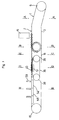
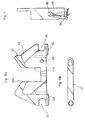
- la figure 1 est une vue schématique longitudinale d'un dispositif conforme à l'invention,
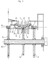
- la figure 2 en est une demi-coupe transversale par un plan vertical A,
- la figure 3 en est une demi-coupe transversale par un plan vertical B,
- la figure 4 en est une demi-coupe transversale par un plan vertical C,
- la figure 5 en est une demi-coupe transversale par un plan vertical D,
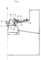
- la figure 6 en est une demi-coupe transversale par un plan vertical E,
- la figure 7 est une demi-vue de dessus partielle de ce dispositif au droit de la zone de transfert,
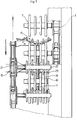
- la figure 8 est une demi-vue de dessus partielle de ce dispositif au droit de la zone de pesée,
- la figure 9 est une demi-vue de dessus partielle de ce dispositif, à une échelle réduite, au droit de la zone de déchargement,
- la figure 10a est une vue latérale d'un chariot de pesée conforme à l'invention,
- la figure 10b est une vue latérale d'une tige de liaison associée à ce chariot,
- et la figure 11 est une vue transversale d'une variante des moyens de déclenchement, représentés en trait plein dans leur position de non sollicitation du système de verrouillage des mains de convoyage, et en traits pointillés dans leur position de basculement de la main de convoyage.
- FIG. 1 is a schematic longitudinal view of a device according to the invention,
- FIG. 2 is a half cross-section thereof through a vertical plane A,
- FIG. 3 is a half cross-section thereof through a vertical plane B,
- FIG. 4 is a half cross-section thereof through a vertical plane C,
- FIG. 5 is a half cross-section thereof through a vertical plane D,
- FIG. 6 is a half cross-section thereof through a vertical plane E,
- FIG. 7 is a partial half-view from above of this device in line with the transfer zone,
- FIG. 8 is a partial half-view from above of this device in line with the weighing area,
- FIG. 9 is a partial half-view from above of this device, on a reduced scale, in line with the unloading area,
- Figure 10a is a side view of a weighing trolley according to the invention,
- FIG. 10b is a side view of a connecting rod associated with this carriage,
- and FIG. 11 is a transverse view of a variant of the triggering means, shown in solid lines in their non-stressing position of the locking system of the conveying hands, and in dotted lines in their tilting position of the conveying hand .
Le dispositif de convoyage représenté aux figures est adapté pour effectuer un tri de produits tels que fruits ou légumes en fonction de critères de sélection prédéterminés tels que le poids et l'aspect externe de ces derniers.The conveying device shown in the figures is suitable for sorting products such as fruit or vegetables according to predetermined selection criteria such as the weight and the external appearance of the latter.
Ce dispositif se divise principalement en une zone de chargement de fruits, par exemple provenant en vrac dans un courant d'eau, une zone d'analyse optique, une zone de transfert, une zone de pesée et une zone de déchargement.This device is mainly divided into a zone for loading fruit, for example coming in bulk in a stream of water, an optical analysis zone, a transfer zone, a weighing zone and an unloading zone.
Dans les zones de chargement et d'analyse optique, les fruits sont transportés par un premier convoyeur, puis transférés sur un deuxième convoyeur dans la zone de transfert, ce deuxième convoyeur assurant leur transport jusque dans la zone de déchargement. En outre, un troisième convoyeur intermédiaire, interposé sur le trajet du deuxième convoyeur, prend en charge momentanément les fruits en vue d'assurer leur pesée. De plus, chacun des convoyeurs comporte deux lignes de convoyage.In the loading and optical analysis zones, the fruits are transported by a first conveyor, then transferred to a second conveyor in the transfer zone, this second conveyor ensuring their transport to the unloading zone. In addition, a third intermediate conveyor, interposed on the path of the second conveyor, temporarily takes charge of the fruits in order to ensure their weighing. In addition, each of the conveyors has two conveyor lines.
En premier lieu, le premier convoyeur est composé de deux lignes de convoyage séparées et identiques, réparties symétriquement de part et d'autre d'un plan de symétrie longitudinal.Firstly, the first conveyor is composed of two separate and identical conveyor lines, distributed symmetrically on either side of a longitudinal plane of symmetry.
Chacune de ces lignes de convoyage comporte une zone de chargement, s'étendant selon une rampe inclinée 1 et une zone d'analyse optique 2 disposée sur une portion de trajet horizontal.Each of these conveyor lines comprises a loading zone, extending along an inclined ramp 1 and an optical analysis zone 2 arranged on a portion of horizontal path.
Chaque ligne de convoyage comporte une chaîne sans fin 3 supportée par un profilé 4 et engrenée autour de deux roues dentées 5, 6.Each conveyor line comprises an
Ces lignes de convoyage sont équipées d'une pluralité de rouleaux tels que 7, adaptés pour définir deux à deux des logements pour les fruits, montés libre en rotation autour d'un axe de rotation 8 solidaire de la chaîne sans fin et s'étendant transversalement par rapport à celle-ci.These conveyor lines are equipped with a plurality of rollers such as 7, adapted to define two by two of the housings for the fruits, mounted free in rotation around a
Chacun des rouleaux 7 comporte un manchon central 9 monté sur l'axe de rotation 8 et des disques verticaux, tels que 10, 11, espacés, s'étendant radialement autour du manchon central 9. Ces disques 10, 11 présentent, en outre, des diamètres différents adaptés pour que chaque rouleau 7 présente une forme externe biconique concave.Each of the
En l'exemple, les disques sont au nombre de quatre : deux disques latéraux tels que 10 de même diamètre, et deux disques centraux tels que 11 de même diamètre, inférieur à celui des disques latéraux. De plus, les tranches de ces disques 10, 11 sont usinées de façon à délimiter une surface d'appui de forme concave.In the example, there are four discs: two lateral discs such as 10 of the same diameter, and two central discs such as 11 of the same diameter, smaller than that of the lateral discs. In addition, the edges of these
De plus, chaque ligne de convoyage du premier convoyeur comporte, au niveau de la zone de chargement 1, une surface de roulement 12, fixe tel que représenté aux figures, ou mobile telle qu'une courroie, apte à provoquer la rotation des rouleaux 7 autour de leur axe de rotation.In addition, each conveyor line of the first conveyor comprises, at the loading area 1, a rolling
Le premier convoyeur comprend, par ailleurs, une pièce de séparation centrale 13 de forme générale triangulaire, disposée longitudinalement entre les rouleaux 7 respectifs des deux lignes de convoyage et adaptée pour assurer le guidage des fruits vers l'une ou l'autre desdites lignes de convoyage.The first conveyor further comprises a
En dernier lieu, le premier convoyeur comporte, de façon classique, dans la zone d'analyse optique 2, des moyens d'entraînement en rotation des rouleaux 7 (non représentés) tel que surface de roulement, courroie... aptes à engendrer une rotation desdits rouleaux à l'aplomb de moyens d'analyse optique 14 de tout type connu en soi tels que caméra...Finally, the first conveyor comprises, conventionally, in the optical analysis zone 2, means for driving in rotation the rollers 7 (not shown) such as rolling surface, belt, etc. capable of generating a rotation of said rollers in line with optical analysis means 14 of any type known per se, such as a camera, etc.
Le deuxième convoyeur comporte, quant à lui, deux lignes de convoyage équipées chacune de mains de convoyage 15 disposées transversalement de part et d'autre d'une chaîne sans fin 16 unique supportée par un profilé 17 s'étendant dans le plan de symétrie longitudinal du dispositif de convoyage.The second conveyor comprises, for its part, two conveyor lines each equipped with
La chaîne sans fin 16 est engrenée autour de deux roues dentées 18, 19 : une roue dentée 18 disposée au niveau de l'extrémité aval du dispositif de convoyage, et une roue dentée 19 montée sur l'arbre 20 d'entraînement en rotation des roues dentées aval 5 du premier convoyeur. Chaque main de convoyage 15 est montée articulée sur un support 21 solidarisé à la chaîne sans fin 16, lesdits support et main de convoyage étant dotés de moyens de verrouillage aptes à maintenir chaque main dans une position de convoyage où elle peut porter un fruit, et à permettre le pivotement de cette main vers une position de déchargement du fruit.The
En premier lieu, chaque main de convoyage 15 comporte une barre centrale transversale 22 de forme concave, de part et d'autre de laquelle s'étendent orthogonalement une pluralité de doigts tels que 23 disposés en regard les uns des autres et incurvés vers le haut, de façon à conférer à ladite main une forme de cuvette allongée selon une direction transversale par rapport à la chaîne sans fin 16, apte à loger un fruit.Firstly, each conveying
De plus, chaque main de convoyage 15 est disposée de façon à venir s'intercaler entre deux rouleaux 7 au droit de la zone de transfert, les doigts 23, en l'exemple au nombre de cinq, étant agencés pour venir encadrer les disques 10, 11 desdits rouleaux.In addition, each conveying
En outre, la barre centrale 22 présente une section en forme de U renversé dont les deux ailes prolongent l'âme au niveau de l'extrémité de fixation sur le support 21, de façon à former une chape logeant un axe de verrouillage horizontal 24. De plus, les deux ailes de ce U sont percées, à distance de l'extrémité précitée, de deux orifices en regard pour le logement de l'axe 25 d'articulation de la main de convoyage 15 sur le support 21.In addition, the
Ce support 21 présente, quant à lui, vue de dessus, la forme d'un T dont chaque aile est solidarisée à la chaîne sans fin 16. La branche de ce T présente, quant à elle, une extrémité 26 comportant longitudinalement une portion en forme de V inversé, d'appui de l'extrémité de la barre centrale 22, respectivement dans ses deux positions de convoyage et de déchargement. Cette extrémité 26 du support 21 est agencée pour être coiffée par la barre transversale 22, et comporte un manchon 27 apte à loger l'axe d'articulation 25.This
De plus, la barre centrale 22 est dotée de deux orifices ménagés dans l'âme de ladite barre et aptes à loger chacun un patin 28, 29 d'appui sur l'extrémité 26 du support 21 respectivement dans les positions de convoyage et de déchargement de la main de convoyage.In addition, the
Les moyens de verrouillage comprennent, quant a eux, un système de loquet comportant une pièce pivotante 30 articulée sur le support 21 et dotée d'un crochet 31 agencé pour coopérer avec l'axe de verrouillage 24 de la main de convoyage. De plus, ce système de loquet comporte un tampon 32 en matériau élastomère porté par le support et agencé pour solliciter la pièce pivotante 30 vers sa position de verrouillage.The locking means comprise, for their part, a latch system comprising a pivoting
Les moyens de verrouillage comportent, enfin, pour chaque ligne de convoyage du deuxième convoyeur, un organe d'appui 33 (représenté à la figure 6) constitué d'un disque vertical interpose sur le trajet de retour dudit convoyeur, et agencé pour venir en contact tangentiel avec chaque main de convoyage 15, disposée dans sa position renversée, de façon a assurer le verrouillage de cette dernière.The locking means comprise, finally, for each conveyor line of the second conveyor, a support member 33 (shown in FIG. 6) consisting of a vertical disc interposed on the return path of said conveyor, and arranged to come in tangential contact with each conveying
Le deuxième convoyeur comporte, par ailleurs, des organes de sécurité aptes à empêcher le basculement de chaque main de convoyage entre la zone de transfert et la zone de déchargement en cas de déficience des moyens de verrouillage.The second conveyor further comprises safety members capable of preventing the tilting of each conveying hand between the transfer zone and the unloading zone in the event of a deficiency in the locking means.
Ces organes de sécurité comportent, en premier lieu, pour chaque ligne de convoyage, un disque 34 porté par l'arbre de rotation 20 entre les roues dentées 5, 19 des premier et deuxième convoyeurs, ledit disque étant agencé pour venir en contact tangentiel sous chaque main de convoyage 15, et présentant une tranche dotée d'encoches pour le passage des rouleaux 7.These safety members comprise, firstly, for each conveyor line, a
Ces organes de sécurité comprennent, en outre, une glissière latérale 35 d'appui éventuel de l'extrémité des mains de convoyage, s'étendant longitudinalement entre la zone de transfert et la zone de déchargement.These safety members further comprise a
Le troisième convoyeur, disposé entre la zone de transfert et la zone de déchargement, comporte deux lignes de convoyage interposées chacune sur le trajet d'une ligne de convoyage du deuxième convoyeur.The third conveyor, arranged between the transfer zone and the unloading zone, comprises two conveyor lines each interposed on the path of a conveyor line of the second conveyor.
Chacune de ces lignes de convoyage comporte une chaîne sans fin 36 montée sur un profilé 37 et engrenée autour de deux roues dentées 38, 39.Each of these conveyor lines comprises an
Chaque ligne de convoyage est équipée de chariots 40 comportant des plaques supports verticales espacées telles que 41, 42, reliées au niveau de leur extrémité inférieure par des traverses 43 et présentant des hauteurs différentes de façon que lesdits chariots présentent transversalement une face supérieure d'appui de forme concave.Each conveyor line is equipped with
De plus, chacune de ces plaques 41, 42 comporte une échancrure centrale 41a, 42a et présente une tranche supérieure s'étendant vers le haut, de part et d'autre de ladite échancrure, de façon à former une face supérieure de support des fruits présentant la forme d'une cuvette.In addition, each of these
En l'exemple, ces plaques sont au nombre de quatre : deux plaques latérales telles que 41 de même hauteur, et deux plaques centrales telles que 42 de même hauteur, inférieure à celle des plaques centrales 42, lesdites plaques latérale 41 et centrale 42 étant décalées longitudinalement et dotées chacune d'une encoche 44, 45 ménagée respectivement au droit de leur extrémité arrière (plaques centrales) et avant (plaques latérales), et formant deux gorges transversales.In the example, these plates are four in number: two lateral plates such as 41 of the same height, and two central plates such as 42 of the same height, less than that of the
Les moyens supports de ces chariots 40 comprennent, en premier lieu, un axe transversal de traction 46 de diamètre inférieur à la hauteur des encoches 44, 45, solidarisé à la chaîne sans fin 36 vers une de ses extrémités et s'étendant à l'intérieur de la gorge avant.The support means of these
Ces moyens supports comportent, en outre, deux bielles latérales telles que 47, disposées de part et d'autre du chariot 40 et articulées respectivement sur l'axe transversal 46 et sur un ergot 48 en saillie par rapport à la face externe des plaques latérales 41, vers l'extrémité arrière de ces dernières.These support means further comprise two lateral connecting rods such as 47, arranged on either side of the
En outre, les chariots 40 sont agencés les uns derrière les autres de façon que la gorge arrière (encoches 45) d'un chariot soit dans l'alignement de la gorge avant (encoches 44) du chariot suivant, la zone arrière du premier chariot étant ainsi supportée par l'axe de traction 46 du chariot suivant.In addition, the
En dernier lieu, chaque plaque 41, 42 est dotée d'un talon inférieur d'appui tel que 49, 50, disposé vers l'extrémité avant des plaques latérales 41, et vers l'extrémité arrière des plaques centrales 42.Finally, each
Chacun de ces chariots 40 est agencé pour venir loger une main de convoyage 15, la barre centrale 22 s'étendant dans les échancrures 41a, 42a, et les doigts 23 étant disposés de part et d'autre des plaques 41, 42. De plus, la hauteur des plaques 41, 42 est adaptée pour que le fruit se trouve porté par le chariot 40, et non par la main de convoyage 15 lorsque lesdits chariot et main sont imbriqués l'un dans l'autre.Each of these
Le troisième convoyeur comprend, enfin, des moyens de pesage classiques, comportant une glissière 51 dotée d'une face supérieure de glissement des talons d'appui 49, 50 des chariots, équipée d'une balance 52 comportant quatre zones de pesage telles que 53 agencées pour se trouver chacune à l'aplomb d'un desdits talons d'appui.The third conveyor finally comprises conventional weighing means, comprising a
La zone de déchargement vers laquelle les fruits sont amenés, portés par les mains de convoyage, comporte des casiers tels que 54, 55 disposés les uns à la suite des autres latéralement de part et d'autre des lignes de convoyage.The unloading area to which the fruits are brought, carried by the conveying hands, comprises compartments such as 54, 55 arranged one after the other laterally on either side of the conveying lines.
De plus, des moyens de déclenchement des moyens de verrouillage sont associés à chacun de ces casiers. Ces moyens de déclenchement comprennent une came 57 dotée d'une rampe d'accès, d'une face plane active et d'une rampe de sortie, et montée pivotante autour d'un axe transversal sur une plaque verticale fixe 58 disposée au-dessus de la ligne de convoyage, dans l'alignement, transversalement, du début de chaque casier 54, 55. Cette came 57 est articulée sur la tige d'un vérin 59 apte à la faire pivoter entre une position haute où elle laisse librement passer la pièce pivotante 30 maintenant verrouillée la main de convoyage 15, et une position basse où elle se trouve disposée sur le trajet de cette pièce pivotante et ou elle entraîne son pivotement et par conséquent la chute de la main de convoyage 15.In addition, means for triggering the locking means are associated with each of these lockers. These triggering means comprise a
De plus, au droit de chaque came 57 se trouve dispose un patin d'appui 62 agence sous le support 21 des mains de convoyage, vers l'extrémité de celui-ci, et destiné à éviter une éventuelle déformation de ce support. Ce patin 62 s'étend, en outre, longitudinalement de part et d'autre de chaque zone de déclenchement de façon à assurer la stabilisation des lignes de convoyage du deuxième convoyeur au cas où une de ces lignes se trouve transporter beaucoup plus de fruits que l'autre.In addition, to the right of each
La figure 11 représente une variante de réalisation des moyens de déclenchement selon laquelle ces derniers comprennent une came 64 dotée d'une rampe d'accès, d'une face plane active et d'une rampe de sortie, montée pivotante autour d'un axe longitudinal sur un support fixe 59.FIG. 11 represents an alternative embodiment of the triggering means according to which the latter comprise a
Cette came est associée à un électro-aimant rotatif 66 apte à la faire pivoter entre une position (représentée en traits pleins à la figure 11) où elle se trouve décalée latéralement par rapport à la trajectoire du crochet 31 et où elle laisse passer librement la pièce pivotante 30, et une position (représentée en traits pointillés à la figure 11) où elle se trouve sur le trajet du crochet 31 et où elle entraîne son pivotement.This cam is associated with a
Par ailleurs, la zone de déchargement est équipée, pour chaque ligne de convoyage, d'une bande transporteuse longitudinale 60 apte à défiler à la même vitesse que ladite ligne de convoyage, et interposée entre celle-ci et les casiers 54, 55.Furthermore, the unloading zone is equipped, for each conveyor line, with a
Cette bande transporteuse 60 est destinée à amortir la chute des mains de convoyage 15 et des fruits.This
De plus, chaque casier est équipé d'un rouleau-brosse 61 destiné à freiner les fruits, monté rotatif autour d'un axe longitudinal horizontal et disposé parallèlement à la bande transporteuse 60.In addition, each rack is equipped with a
Enfin, un volet à axe horizontal, schématisé en 63, est disposé au-dessus de la bande transporteuse 60, dans le prolongement de chaque cloison de séparation entre les casiers 54, 55. Ce volet 63 agencé pour être soulevé lorsqu'un fruit est présent sur la bande transporteuse 60 au droit d'une cloison de séparation, présence signifiant que le casier précédent est rempli, est destine a constituer un organe de détection apte à commander un arrêt d'urgence.Finally, a flap with a horizontal axis, shown diagrammatically at 63, is disposed above the
Claims (18)
Applications Claiming Priority (2)
| Application Number | Priority Date | Filing Date | Title |
|---|---|---|---|
| FR9402675 | 1994-03-03 | ||
| FR9402675A FR2716874B1 (en) | 1994-03-03 | 1994-03-03 | Conveying device for products, especially fruit, suitable for sorting said products according to predetermined selection criteria. |
Publications (2)
| Publication Number | Publication Date |
|---|---|
| EP0670276A1 true EP0670276A1 (en) | 1995-09-06 |
| EP0670276B1 EP0670276B1 (en) | 1998-01-28 |
Family
ID=9460813
Family Applications (1)
| Application Number | Title | Priority Date | Filing Date |
|---|---|---|---|
| EP95200464A Expired - Lifetime EP0670276B1 (en) | 1994-03-03 | 1995-02-24 | Conveying device for products, especially for fruits, adapted for sorting the said products according the predetermined features of selection |
Country Status (16)
| Country | Link |
|---|---|
| US (1) | US5626238A (en) |
| EP (1) | EP0670276B1 (en) |
| JP (1) | JP3616421B2 (en) |
| CN (1) | CN1054824C (en) |
| AU (1) | AU690184B2 (en) |
| BR (1) | BR9500810A (en) |
| CA (1) | CA2143048C (en) |
| DE (1) | DE69501505T2 (en) |
| DK (1) | DK0670276T3 (en) |
| ES (1) | ES2112604T3 (en) |
| FR (1) | FR2716874B1 (en) |
| GR (1) | GR3026578T3 (en) |
| IL (1) | IL112702A (en) |
| NZ (1) | NZ270556A (en) |
| RU (1) | RU2139231C1 (en) |
| ZA (1) | ZA951481B (en) |
Cited By (12)
| Publication number | Priority date | Publication date | Assignee | Title |
|---|---|---|---|---|
| FR2755956A1 (en) * | 1996-11-21 | 1998-05-22 | Materiel Arboriculture | Conveyor for spherical products such as melons |
| FR2812857A1 (en) | 2000-08-09 | 2002-02-15 | Materiel Arboriculture | Grading and preserving peaches, apricots, nectarines comprises placing grade fruit into pallets, putting stacked pallets in refrigerated chamber, grading and removing pallets for packaging |
| US6374983B1 (en) | 1999-06-29 | 2002-04-23 | Romana Amaducci Morigi | Conveyor for the selection of fruit |
| US7159373B2 (en) | 2004-03-23 | 2007-01-09 | Material Pour L'arboriculture Fruitiere | Installation for hydraulically filling crates with floating objects such as fruits and having a single double-acting pump |
| US7280198B2 (en) | 2004-08-17 | 2007-10-09 | Materiel Pour L'arboriculture Fruitiere | Apparatus for optically analyzing products such as fruit having bilateral imaging devices |
| WO2012056186A3 (en) * | 2010-10-29 | 2012-07-12 | Maf Agrobotic | Device for grouping floating objects into batches, having a motor-driven push member for stacking the objects |
| WO2012146841A1 (en) | 2011-03-09 | 2012-11-01 | Maf Agrobotic | Accelerometer-controlled positive-drive device and method for the non-destructive measurement of firmness |
| FR2976196A1 (en) * | 2011-06-10 | 2012-12-14 | Maf Agrobotic | DEVICE FOR CONVEYING OBJECTS SUCH AS FRUIT OR VEGETABLES WITH ZONES BEGINNING OF BILATERAL INDIVIDUALIZATION |
| FR2983458A1 (en) * | 2011-12-06 | 2013-06-07 | Maf Agrobotic | Method for continuous packaging of e.g. objects, involves arranging buffer packing zone with cells, and continuously transferring objects by intermediate conveyor between buffer packing zone and filling zone |
| CN107350171A (en) * | 2017-08-23 | 2017-11-17 | 安徽鼎封橡胶减震技术有限公司 | A kind of new type auto sorting detection device |
| EP3010810B1 (en) | 2013-06-17 | 2017-12-20 | Unisorting S.r.l. | A system for packaging products |
| CN115676253A (en) * | 2023-01-03 | 2023-02-03 | 四川远方云天食品科技有限公司 | Chain plate type conveying device for fluid hot pot packaging bag limiting type screening detection |
Families Citing this family (42)
| Publication number | Priority date | Publication date | Assignee | Title |
|---|---|---|---|---|
| AUPM762094A0 (en) * | 1994-08-24 | 1994-09-15 | Colour Vision Systems Pty Ltd | Conveying system for foodstuffs |
| IL117242A0 (en) | 1996-02-23 | 1996-06-18 | Orbotech Ltd | Conveyor system having selectively enabled conveyor elements |
| IL120071A (en) * | 1997-01-24 | 2002-03-10 | Orbotech Ltd | Method and system for continuously processing workpieces along a production line |
| FR2772358B1 (en) | 1997-12-16 | 2000-03-10 | Materiel Arboriculture | DEVICE FOR CONVEYING PRODUCTS, ESPECIALLY FRUIT, FOR SUPPLYING A SORTING UNIT FOR SAID PRODUCTS |
| FR2785892B1 (en) | 1998-11-13 | 2001-03-02 | Materiel Arboriculture | DEVICE FOR CONVEYING PRODUCTS, ESPECIALLY FRUIT |
| US6267249B1 (en) * | 1999-05-19 | 2001-07-31 | Exeter Engineering Inc. | Transport system for an automatic article grading apparatus |
| NL1012258C2 (en) * | 1999-06-08 | 2000-12-11 | Greefs Wagen Carrosserie | Device for aiming a number of similar objects such as fruits. |
| ES2159244B1 (en) * | 1999-07-30 | 2002-04-01 | Miguel Antonio Ortiz | MACHINE FOR CLASSIFICATION BY CALIBER OF FRUITS. |
| JP4802416B2 (en) * | 2001-07-09 | 2011-10-26 | 株式会社横崎製作所 | Fruit sorting device |
| NZ518851A (en) * | 2002-05-08 | 2004-12-24 | Anzpac Systems Ltd | Sorting apparatus and method |
| AUPS319602A0 (en) * | 2002-06-26 | 2002-07-18 | Colour Vision Systems Pty Ltd | Fruit handling equipment |
| CN1867412B (en) * | 2003-10-09 | 2010-08-25 | Fps食品加工系统公司 | Carrier for sorting apparatus |
| GB0405801D0 (en) * | 2004-03-16 | 2004-04-21 | Herbert Roderic J | Apparatus for aligning crop for grading articles |
| FR2874424B1 (en) * | 2004-08-17 | 2007-05-11 | Materiel Arboriculture | DEVICE FOR OPTICALLY ANALYZING PRODUCTS SUCH AS INDIRECT LIGHT FRUITS |
| JP2006321623A (en) * | 2005-05-19 | 2006-11-30 | Dainippon Screen Mfg Co Ltd | Substrate carrying device |
| CN101139044B (en) * | 2007-09-28 | 2011-02-09 | 浙江大学 | Fruit accurate transition system based on phase adjustment |
| EP2389331B1 (en) | 2009-01-23 | 2017-06-21 | MAF Agrobotic S.A.S. | Fruit handling equipment |
| NL2003516C2 (en) * | 2009-09-21 | 2011-03-22 | Greefs Wagen Carrosserie | TRANSPORTATION DEVICE FOR TRANSPORTING A PRODUCT, AND SORTING DEVICE AND METHOD FOR THIS. |
| CN101844136A (en) * | 2010-04-29 | 2010-09-29 | 扬州福尔喜果蔬汁机械有限公司 | Bruise-free fruit transition and conversion device |
| FR2963611B1 (en) | 2010-08-03 | 2013-12-06 | Maf Agrobotic | DEVICE FOR CONVEYING OBJECTS SUCH AS FRUIT OR VEGETABLE WITH ADJUSTABLE DISCHARGE POSITIONS |
| FR2999550B1 (en) | 2012-12-14 | 2015-01-16 | Maf Agrobotic | METHOD AND DEVICE FOR GROUPING LOTS OF FLOATING OBJECTS WITH HYDRAULIC SUPERPOSITION OF OBJECTS |
| CN103910165B (en) * | 2013-11-27 | 2016-02-03 | 大连隆星新材料有限公司 | Particle paraffin belt conveyor |
| AU2015228497B2 (en) * | 2014-03-10 | 2019-05-16 | Food Machinery Crescenzo S.R.L. | Machine for recognizing and orienting fruits and method |
| MX2016007919A (en) * | 2014-07-02 | 2016-09-13 | Doben Ltd | System and method with drag conveyor for high rate production welding. |
| KR101494135B1 (en) * | 2014-07-11 | 2015-02-16 | 한국지에이피아 주식회사 | Apparatus for sorting fruit |
| EP3187441B1 (en) | 2015-12-29 | 2022-04-20 | Grupo Celulosas Moldeadas, S.L. | Method for destacking trays |
| FR3049269B1 (en) | 2016-03-25 | 2020-01-03 | Maf Agrobotic | METHOD AND APPARATUS FOR HYDRAULIC FILLING OF BOXES WITH FORCED POWERED FLOATING OBJECTS |
| FR3050665B1 (en) | 2016-04-28 | 2018-04-20 | Maf Agrobotic | METHOD AND DEVICE FOR ORIENTATION OF AN OMBILIC FRUIT, IN PARTICULAR FOR PACKAGING |
| FR3055890A1 (en) | 2016-09-15 | 2018-03-16 | Maf Agrobotic | DEVICE AND METHOD FOR GROUPING AND TRANSFERRING PALLET BOXES OF BATCHED PRODUCTS |
| CN106418652B (en) * | 2016-11-16 | 2017-10-17 | 昆明钦瑜机械有限公司 | A kind of former smoked sheet selects system |
| FR3063542A1 (en) | 2017-03-01 | 2018-09-07 | Maf Agrobotic | METHOD AND APPARATUS FOR OPTICAL ANALYSIS OF FRUIT OR VEGETABLES AND AUTOMATIC SORTING DEVICE |
| FR3073509B1 (en) | 2017-11-15 | 2022-04-08 | Maf Agrobotic | DEVICE FOR CONSOLIDATING FRUITS OR VEGETABLES IN LOTS WITH ACCUMULATION CHANNELS PROVIDED WITH BY-PASS PASSAGES |
| FR3075770B1 (en) | 2017-12-22 | 2020-01-03 | Maf Agrobotic | METHOD AND DEVICE FOR GROUPING LOTS OF FLOATING OBJECTS WITH DYNAMIC HYDRAULIC OVERLAY OF OBJECTS |
| CN108263856B (en) * | 2018-01-05 | 2020-11-27 | 上海第二工业大学 | Robot intelligent rapid carrying device based on machine vision and carrying method thereof |
| CN109433630B (en) * | 2018-12-17 | 2023-11-14 | 沅江兴农机械制造有限公司 | Fruit sorting system using optical analysis |
| CN110282394A (en) * | 2019-06-15 | 2019-09-27 | 泰州市旺灵绝缘材料厂 | A kind of board transfer apparatus |
| US11851218B1 (en) * | 2019-09-23 | 2023-12-26 | Amazon Technologies, Inc. | Material handling apparatus |
| IT202100018389A1 (en) * | 2021-07-13 | 2023-01-13 | Unitec Spa | TRANSPORT EQUIPMENT FOR FRUIT AND VEGETABLE PRODUCTS |
| NL2028839B1 (en) * | 2021-07-26 | 2023-01-31 | De Greefs Wagen Carrosserie En Machb B V | PACKAGING DEVICE FOR THE TARGETED PACKAGING OF PRODUCTS SUCH AS FRUIT AND VEGETABLES, SORTING SYSTEM OR PACKAGING LINE PROVIDED WITH THEREOF AND METHOD FOR THEREOF |
| CN114524256B (en) * | 2022-04-25 | 2022-07-08 | 李艳红 | Conveying device matched with agricultural technical equipment |
| CN115947101B (en) * | 2023-03-15 | 2023-06-13 | 四川翔越电力线路构件有限公司 | Angle steel material loading separation transfer device |
| CN117819129A (en) * | 2024-03-01 | 2024-04-05 | 康辉南通新材料科技有限公司 | One-way non-return device of lithium ion diaphragm conveying line body |
Citations (3)
| Publication number | Priority date | Publication date | Assignee | Title |
|---|---|---|---|---|
| EP0283388A1 (en) * | 1987-03-11 | 1988-09-21 | Xeda International | System to calibrate products, such as fruits |
| US4830195A (en) * | 1986-01-31 | 1989-05-16 | 501 De Greef's Wagen | High speed mechanical weighing system |
| EP0540126A1 (en) * | 1991-10-30 | 1993-05-05 | Adrianus Wilhelmus Tas | Apparatus for sorting spherical products according to weight |
Family Cites Families (10)
| Publication number | Priority date | Publication date | Assignee | Title |
|---|---|---|---|---|
| US2980252A (en) * | 1958-03-24 | 1961-04-18 | Fmc Corp | Fruit grading machine |
| US3372804A (en) * | 1965-09-30 | 1968-03-12 | Puoti Lionello | Automatic machine for checking the weight of open cans containing liquid or semiliquid substances |
| GB1291564A (en) * | 1968-11-29 | 1972-10-04 | Crisplant As | Improvements in or relating to conveyor systems |
| US4254877A (en) * | 1979-11-05 | 1981-03-10 | Fmc Corporation | Weight sizing apparatus |
| NL182940C (en) * | 1980-03-31 | 1988-06-16 | Greefs Wagen Carrosserie | DEVICE FOR SORTING PRODUCTS SUCH AS FRUITS. |
| US5307921A (en) * | 1990-12-17 | 1994-05-03 | Australian Postal Corporation | Tilt tray sorter accessory |
| FR2680359B1 (en) * | 1991-08-14 | 1994-02-18 | Materiel Arboriculture Fruitiere | DEVICE FOR CONVEYING PRODUCTS, ESPECIALLY FRUIT. |
| US5294004A (en) * | 1991-08-19 | 1994-03-15 | Durand-Wayland, Inc. | Article-holding cup and scale for apparatus that sorts articles by weight |
| US5197585A (en) * | 1992-03-06 | 1993-03-30 | Agri-Tech Incorporated | Object sorting apparatus with object holder facilitating lateral transfer |
| US5267654A (en) * | 1992-05-26 | 1993-12-07 | Durand-Wayland, Inc. | Article-holding cup and sorting apparatus |
-
1994
- 1994-03-03 FR FR9402675A patent/FR2716874B1/en not_active Expired - Fee Related
-
1995
- 1995-02-20 IL IL112702A patent/IL112702A/en not_active IP Right Cessation
- 1995-02-21 CA CA002143048A patent/CA2143048C/en not_active Expired - Fee Related
- 1995-02-22 ZA ZA951481A patent/ZA951481B/en unknown
- 1995-02-23 NZ NZ270556A patent/NZ270556A/en not_active IP Right Cessation
- 1995-02-23 AU AU13452/95A patent/AU690184B2/en not_active Ceased
- 1995-02-24 ES ES95200464T patent/ES2112604T3/en not_active Expired - Lifetime
- 1995-02-24 DK DK95200464T patent/DK0670276T3/en active
- 1995-02-24 DE DE69501505T patent/DE69501505T2/en not_active Expired - Lifetime
- 1995-02-24 EP EP95200464A patent/EP0670276B1/en not_active Expired - Lifetime
- 1995-03-02 RU RU95103097A patent/RU2139231C1/en active
- 1995-03-03 JP JP08163795A patent/JP3616421B2/en not_active Expired - Fee Related
- 1995-03-03 BR BR9500810A patent/BR9500810A/en not_active IP Right Cessation
- 1995-03-03 CN CN95103294A patent/CN1054824C/en not_active Expired - Lifetime
- 1995-03-03 US US08/397,977 patent/US5626238A/en not_active Expired - Lifetime
-
1998
- 1998-04-09 GR GR980400766T patent/GR3026578T3/en unknown
Patent Citations (3)
| Publication number | Priority date | Publication date | Assignee | Title |
|---|---|---|---|---|
| US4830195A (en) * | 1986-01-31 | 1989-05-16 | 501 De Greef's Wagen | High speed mechanical weighing system |
| EP0283388A1 (en) * | 1987-03-11 | 1988-09-21 | Xeda International | System to calibrate products, such as fruits |
| EP0540126A1 (en) * | 1991-10-30 | 1993-05-05 | Adrianus Wilhelmus Tas | Apparatus for sorting spherical products according to weight |
Cited By (16)
| Publication number | Priority date | Publication date | Assignee | Title |
|---|---|---|---|---|
| FR2755956A1 (en) * | 1996-11-21 | 1998-05-22 | Materiel Arboriculture | Conveyor for spherical products such as melons |
| US6374983B1 (en) | 1999-06-29 | 2002-04-23 | Romana Amaducci Morigi | Conveyor for the selection of fruit |
| FR2812857A1 (en) | 2000-08-09 | 2002-02-15 | Materiel Arboriculture | Grading and preserving peaches, apricots, nectarines comprises placing grade fruit into pallets, putting stacked pallets in refrigerated chamber, grading and removing pallets for packaging |
| US7159373B2 (en) | 2004-03-23 | 2007-01-09 | Material Pour L'arboriculture Fruitiere | Installation for hydraulically filling crates with floating objects such as fruits and having a single double-acting pump |
| US7280198B2 (en) | 2004-08-17 | 2007-10-09 | Materiel Pour L'arboriculture Fruitiere | Apparatus for optically analyzing products such as fruit having bilateral imaging devices |
| WO2012056186A3 (en) * | 2010-10-29 | 2012-07-12 | Maf Agrobotic | Device for grouping floating objects into batches, having a motor-driven push member for stacking the objects |
| WO2012146841A1 (en) | 2011-03-09 | 2012-11-01 | Maf Agrobotic | Accelerometer-controlled positive-drive device and method for the non-destructive measurement of firmness |
| FR2976195A1 (en) * | 2011-06-10 | 2012-12-14 | Maf Agrobotic | Device for conveying objects e.g. vegetables, has conveyor for forming pair of conveying lines, and carpet receiving and recycling objects falling laterally, where upper part of each conveying line includes inner zone placed at loading ends |
| FR2976196A1 (en) * | 2011-06-10 | 2012-12-14 | Maf Agrobotic | DEVICE FOR CONVEYING OBJECTS SUCH AS FRUIT OR VEGETABLES WITH ZONES BEGINNING OF BILATERAL INDIVIDUALIZATION |
| ES2405840R1 (en) * | 2011-06-10 | 2013-06-19 | Maf Agrobotic | Device for transporting objects such as fruits and vegetables in upstream areas of bilateral individualization. |
| FR2983458A1 (en) * | 2011-12-06 | 2013-06-07 | Maf Agrobotic | Method for continuous packaging of e.g. objects, involves arranging buffer packing zone with cells, and continuously transferring objects by intermediate conveyor between buffer packing zone and filling zone |
| EP3010810B1 (en) | 2013-06-17 | 2017-12-20 | Unisorting S.r.l. | A system for packaging products |
| CN107350171A (en) * | 2017-08-23 | 2017-11-17 | 安徽鼎封橡胶减震技术有限公司 | A kind of new type auto sorting detection device |
| CN107350171B (en) * | 2017-08-23 | 2023-05-02 | 安徽鼎封橡胶减震技术有限公司 | Automatic sorting and detecting equipment |
| CN115676253A (en) * | 2023-01-03 | 2023-02-03 | 四川远方云天食品科技有限公司 | Chain plate type conveying device for fluid hot pot packaging bag limiting type screening detection |
| CN115676253B (en) * | 2023-01-03 | 2023-03-28 | 四川远方云天食品科技有限公司 | Chain plate type conveying device for fluid hot pot packaging bag limiting type screening detection |
Also Published As
| Publication number | Publication date |
|---|---|
| EP0670276B1 (en) | 1998-01-28 |
| AU1345295A (en) | 1995-09-14 |
| ES2112604T3 (en) | 1998-04-01 |
| CA2143048C (en) | 2004-02-17 |
| DE69501505T2 (en) | 1998-09-10 |
| JP3616421B2 (en) | 2005-02-02 |
| BR9500810A (en) | 1995-10-24 |
| FR2716874A1 (en) | 1995-09-08 |
| NZ270556A (en) | 1997-02-24 |
| ZA951481B (en) | 1996-01-07 |
| FR2716874B1 (en) | 1996-06-21 |
| CN1120511A (en) | 1996-04-17 |
| GR3026578T3 (en) | 1998-07-31 |
| RU2139231C1 (en) | 1999-10-10 |
| CA2143048A1 (en) | 1995-09-04 |
| US5626238A (en) | 1997-05-06 |
| DE69501505D1 (en) | 1998-03-05 |
| JPH07265812A (en) | 1995-10-17 |
| IL112702A (en) | 1998-01-04 |
| DK0670276T3 (en) | 1998-09-21 |
| IL112702A0 (en) | 1995-05-26 |
| RU95103097A (en) | 1997-01-20 |
| AU690184B2 (en) | 1998-04-23 |
| CN1054824C (en) | 2000-07-26 |
Similar Documents
| Publication | Publication Date | Title |
|---|---|---|
| EP0670276B1 (en) | Conveying device for products, especially for fruits, adapted for sorting the said products according the predetermined features of selection | |
| EP3283857B1 (en) | Device for transporting objects and conveying and weighing device provided with such transporting devices | |
| EP0491407B1 (en) | Conveying device for products, especially for fruits, adapted for sorting the said products according to predetermined features of selection | |
| FR2631945A1 (en) | SAS WITH CELLULAR WHEEL | |
| WO2011012802A1 (en) | Item accumulation table for conveying equipment | |
| FR2473869A1 (en) | EGG BREAKING MACHINE AND SEPARATING THE CONTENT | |
| EP2096053A1 (en) | One chained pallet accumulation conveyor | |
| EP1000883B1 (en) | Conveyor device for products, in particular fruits | |
| FR2956103A1 (en) | Belt lift conveyor structure, has ramp connected to one of sections of path by another pivot connection of another axle parallel to axle and connected to other section by slider connection | |
| FR2960866A1 (en) | Conveying receptacle for conveying object e.g. fruit, in conveying device, has beam respectively articulated from two sides at base and support along pivoting axes, where axes are located on two sides of longitudinal median plane of foot | |
| FR2860506A1 (en) | CARRIER TYPE OF CARRIAGE DRIVEN BY FRICTION | |
| FR2976196A1 (en) | DEVICE FOR CONVEYING OBJECTS SUCH AS FRUIT OR VEGETABLES WITH ZONES BEGINNING OF BILATERAL INDIVIDUALIZATION | |
| BE897696A (en) | CONVEYOR AND ITS PUSHING DEVICE | |
| FR2607121A1 (en) | ACCUMULATION CONVEYOR | |
| EP0810963B1 (en) | Feed device for a sorting unit, sorting unit with such a feed device, a grading device and distribution device | |
| CA2404148A1 (en) | Automatic selective sorting device | |
| FR2951444A1 (en) | DEVICE FOR PRODUCING LOTS OF PRODUCTS FOR THEIR LOADING IN RECEPTACLES | |
| EP2252493A2 (en) | Car for handling heavy loads, particular a railway one, and use of said car in the presence of a catenary system | |
| FR2500417A1 (en) | DYNAMIC STORAGE FACILITIES | |
| FR2726800A1 (en) | DEVICE FOR AUTOMATICALLY SETTING CYLINDRICAL PARTS AND WAGON USING SUCH A DEVICE | |
| FR2858597A1 (en) | Automatic packing device for filling of containers with products, has rotary shaft and motor capable of pivoting successive strips of conveyor in opposite directions of rotation to form waves of products on conveyor | |
| FR2516486A1 (en) | CONVEYOR WITH COMPARTMENT FOR CONVEYING OBJECTS ON A WEIGHING STATION, IN PARTICULAR FOR CLASSIFYING FRUIT | |
| FR2523300A1 (en) | Weighing machine for fruit and vegetables - has containers with rolling triangular support on track and drive independent weighing operation | |
| FR2495585A1 (en) | CONVEYOR WITH PUSHERS OR SCRAPERS | |
| CA2214092C (en) | Feed device for a sorting unit, sorting unit with a grading device, and distribution device |
Legal Events
| Date | Code | Title | Description |
|---|---|---|---|
| PUAI | Public reference made under article 153(3) epc to a published international application that has entered the european phase |
Free format text: ORIGINAL CODE: 0009012 |
|
| AK | Designated contracting states |
Kind code of ref document: A1 Designated state(s): BE DE DK ES FR GB GR IE IT NL PT |
|
| 17P | Request for examination filed |
Effective date: 19960115 |
|
| 17Q | First examination report despatched |
Effective date: 19961023 |
|
| GRAG | Despatch of communication of intention to grant |
Free format text: ORIGINAL CODE: EPIDOS AGRA |
|
| GRAG | Despatch of communication of intention to grant |
Free format text: ORIGINAL CODE: EPIDOS AGRA |
|
| GRAH | Despatch of communication of intention to grant a patent |
Free format text: ORIGINAL CODE: EPIDOS IGRA |
|
| ITCL | It: translation for ep claims filed |
Representative=s name: ING. FRANCO RASTELLI |
|
| GRAH | Despatch of communication of intention to grant a patent |
Free format text: ORIGINAL CODE: EPIDOS IGRA |
|
| GRAA | (expected) grant |
Free format text: ORIGINAL CODE: 0009210 |
|
| AK | Designated contracting states |
Kind code of ref document: B1 Designated state(s): BE DE DK ES FR GB GR IE IT NL PT |
|
| REF | Corresponds to: |
Ref document number: 69501505 Country of ref document: DE Date of ref document: 19980305 |
|
| ITF | It: translation for a ep patent filed |
Owner name: DOTT. ING. FRANCO RASTELLI |
|
| REG | Reference to a national code |
Ref country code: ES Ref legal event code: FG2A Ref document number: 2112604 Country of ref document: ES Kind code of ref document: T3 |
|
| GBT | Gb: translation of ep patent filed (gb section 77(6)(a)/1977) |
Effective date: 19980430 |
|
| REG | Reference to a national code |
Ref country code: PT Ref legal event code: SC4A Free format text: AVAILABILITY OF NATIONAL TRANSLATION Effective date: 19980302 |
|
| REG | Reference to a national code |
Ref country code: IE Ref legal event code: FG4D Free format text: 78694 |
|
| REG | Reference to a national code |
Ref country code: DK Ref legal event code: T3 |
|
| PLBE | No opposition filed within time limit |
Free format text: ORIGINAL CODE: 0009261 |
|
| STAA | Information on the status of an ep patent application or granted ep patent |
Free format text: STATUS: NO OPPOSITION FILED WITHIN TIME LIMIT |
|
| 26N | No opposition filed | ||
| REG | Reference to a national code |
Ref country code: GB Ref legal event code: IF02 |
|
| REG | Reference to a national code |
Ref country code: PT Ref legal event code: MM4A Free format text: LAPSE DUE TO NON-PAYMENT OF FEES Effective date: 20090824 |
|
| PG25 | Lapsed in a contracting state [announced via postgrant information from national office to epo] |
Ref country code: PT Free format text: LAPSE BECAUSE OF NON-PAYMENT OF DUE FEES Effective date: 20090824 |
|
| REG | Reference to a national code |
Ref country code: PT Ref legal event code: NF4A Free format text: RESTITUTIO IN INTEGRUM Effective date: 20100222 |
|
| PGRI | Patent reinstated in contracting state [announced from national office to epo] |
Ref country code: PT Effective date: 20100222 |
|
| PGFP | Annual fee paid to national office [announced via postgrant information from national office to epo] |
Ref country code: GR Payment date: 20101227 Year of fee payment: 17 |
|
| PGFP | Annual fee paid to national office [announced via postgrant information from national office to epo] |
Ref country code: DK Payment date: 20110210 Year of fee payment: 17 Ref country code: IE Payment date: 20110210 Year of fee payment: 17 |
|
| PGFP | Annual fee paid to national office [announced via postgrant information from national office to epo] |
Ref country code: BE Payment date: 20120103 Year of fee payment: 18 |
|
| REG | Reference to a national code |
Ref country code: DK Ref legal event code: EBP |
|
| REG | Reference to a national code |
Ref country code: IE Ref legal event code: MM4A |
|
| PG25 | Lapsed in a contracting state [announced via postgrant information from national office to epo] |
Ref country code: IE Free format text: LAPSE BECAUSE OF NON-PAYMENT OF DUE FEES Effective date: 20120224 |
|
| PGFP | Annual fee paid to national office [announced via postgrant information from national office to epo] |
Ref country code: GB Payment date: 20130220 Year of fee payment: 19 Ref country code: DE Payment date: 20130225 Year of fee payment: 19 |
|
| PGFP | Annual fee paid to national office [announced via postgrant information from national office to epo] |
Ref country code: PT Payment date: 20130222 Year of fee payment: 19 |
|
| BERE | Be: lapsed |
Owner name: S.A. MATERIEL POUR L'ARBORICULTURE FRUITIERE *MAF Effective date: 20130228 |
|
| REG | Reference to a national code |
Ref country code: GR Ref legal event code: ML Ref document number: 980400766 Country of ref document: GR Effective date: 20130904 |
|
| PG25 | Lapsed in a contracting state [announced via postgrant information from national office to epo] |
Ref country code: GR Free format text: LAPSE BECAUSE OF NON-PAYMENT OF DUE FEES Effective date: 20130904 Ref country code: DK Free format text: LAPSE BECAUSE OF NON-PAYMENT OF DUE FEES Effective date: 20120229 |
|
| PG25 | Lapsed in a contracting state [announced via postgrant information from national office to epo] |
Ref country code: BE Free format text: LAPSE BECAUSE OF NON-PAYMENT OF DUE FEES Effective date: 20130228 |
|
| PGFP | Annual fee paid to national office [announced via postgrant information from national office to epo] |
Ref country code: NL Payment date: 20140218 Year of fee payment: 20 |
|
| PGFP | Annual fee paid to national office [announced via postgrant information from national office to epo] |
Ref country code: ES Payment date: 20131227 Year of fee payment: 20 Ref country code: IT Payment date: 20140128 Year of fee payment: 20 Ref country code: FR Payment date: 20140221 Year of fee payment: 20 |
|
| REG | Reference to a national code |
Ref country code: DE Ref legal event code: R119 Ref document number: 69501505 Country of ref document: DE Ref country code: PT Ref legal event code: MM4A Free format text: LAPSE DUE TO NON-PAYMENT OF FEES Effective date: 20140825 |
|
| GBPC | Gb: european patent ceased through non-payment of renewal fee |
Effective date: 20140224 |
|
| REG | Reference to a national code |
Ref country code: DE Ref legal event code: R119 Ref document number: 69501505 Country of ref document: DE Effective date: 20140902 |
|
| PG25 | Lapsed in a contracting state [announced via postgrant information from national office to epo] |
Ref country code: PT Free format text: LAPSE BECAUSE OF NON-PAYMENT OF DUE FEES Effective date: 20140825 |
|
| PG25 | Lapsed in a contracting state [announced via postgrant information from national office to epo] |
Ref country code: GB Free format text: LAPSE BECAUSE OF NON-PAYMENT OF DUE FEES Effective date: 20140224 Ref country code: DE Free format text: LAPSE BECAUSE OF NON-PAYMENT OF DUE FEES Effective date: 20140902 |
|
| REG | Reference to a national code |
Ref country code: PT Ref legal event code: MM4A Free format text: MAXIMUM VALIDITY LIMIT REACHED Effective date: 20150224 |
|
| REG | Reference to a national code |
Ref country code: NL Ref legal event code: V4 Effective date: 20150224 |
|
| PG25 | Lapsed in a contracting state [announced via postgrant information from national office to epo] |
Ref country code: PT Free format text: LAPSE BECAUSE OF EXPIRATION OF PROTECTION Effective date: 20150303 |
|
| REG | Reference to a national code |
Ref country code: ES Ref legal event code: FD2A Effective date: 20150826 |
|
| PG25 | Lapsed in a contracting state [announced via postgrant information from national office to epo] |
Ref country code: ES Free format text: LAPSE BECAUSE OF EXPIRATION OF PROTECTION Effective date: 20150225 |
|
| PG25 | Lapsed in a contracting state [announced via postgrant information from national office to epo] |
Ref country code: PT Free format text: LAPSE BECAUSE OF EXPIRATION OF PROTECTION Effective date: 20140224 |