EP0667309B1 - Werkstück-Behandlungsvorrichtung - Google Patents
Werkstück-Behandlungsvorrichtung Download PDFInfo
- Publication number
- EP0667309B1 EP0667309B1 EP95101461A EP95101461A EP0667309B1 EP 0667309 B1 EP0667309 B1 EP 0667309B1 EP 95101461 A EP95101461 A EP 95101461A EP 95101461 A EP95101461 A EP 95101461A EP 0667309 B1 EP0667309 B1 EP 0667309B1
- Authority
- EP
- European Patent Office
- Prior art keywords
- zone
- under
- section
- drying device
- cross
- Prior art date
- Legal status (The legal status is an assumption and is not a legal conclusion. Google has not performed a legal analysis and makes no representation as to the accuracy of the status listed.)
- Expired - Lifetime
Links
- 238000001035 drying Methods 0.000 claims description 21
- 229920001343 polytetrafluoroethylene Polymers 0.000 claims description 7
- 239000004810 polytetrafluoroethylene Substances 0.000 claims description 7
- 239000004033 plastic Substances 0.000 claims description 5
- 229920003023 plastic Polymers 0.000 claims description 5
- -1 polytetrafluoroethylene Polymers 0.000 claims description 5
- 239000000463 material Substances 0.000 claims description 2
- 239000002184 metal Substances 0.000 claims description 2
- 238000007688 edging Methods 0.000 claims 2
- 229920003235 aromatic polyamide Polymers 0.000 claims 1
- 239000011248 coating agent Substances 0.000 claims 1
- 238000000576 coating method Methods 0.000 claims 1
- 239000006223 plastic coating Substances 0.000 description 9
- 238000005192 partition Methods 0.000 description 6
- 230000035699 permeability Effects 0.000 description 5
- 239000004760 aramid Substances 0.000 description 4
- 229920006231 aramid fiber Polymers 0.000 description 4
- 239000002390 adhesive tape Substances 0.000 description 3
- 238000010438 heat treatment Methods 0.000 description 3
- 230000008901 benefit Effects 0.000 description 2
- 230000015572 biosynthetic process Effects 0.000 description 2
- 238000001816 cooling Methods 0.000 description 2
- 230000000694 effects Effects 0.000 description 2
- 230000002093 peripheral effect Effects 0.000 description 2
- RNFJDJUURJAICM-UHFFFAOYSA-N 2,2,4,4,6,6-hexaphenoxy-1,3,5-triaza-2$l^{5},4$l^{5},6$l^{5}-triphosphacyclohexa-1,3,5-triene Chemical compound N=1P(OC=2C=CC=CC=2)(OC=2C=CC=CC=2)=NP(OC=2C=CC=CC=2)(OC=2C=CC=CC=2)=NP=1(OC=1C=CC=CC=1)OC1=CC=CC=C1 RNFJDJUURJAICM-UHFFFAOYSA-N 0.000 description 1
- 229910000831 Steel Inorganic materials 0.000 description 1
- 239000000853 adhesive Substances 0.000 description 1
- 230000001070 adhesive effect Effects 0.000 description 1
- 238000005452 bending Methods 0.000 description 1
- 208000018459 dissociative disease Diseases 0.000 description 1
- 238000005516 engineering process Methods 0.000 description 1
- 239000003063 flame retardant Substances 0.000 description 1
- 230000006872 improvement Effects 0.000 description 1
- 238000002955 isolation Methods 0.000 description 1
- 238000004519 manufacturing process Methods 0.000 description 1
- 239000010959 steel Substances 0.000 description 1
- 239000000126 substance Substances 0.000 description 1
- 230000007704 transition Effects 0.000 description 1
- 238000004073 vulcanization Methods 0.000 description 1
Images



Classifications
-
- F—MECHANICAL ENGINEERING; LIGHTING; HEATING; WEAPONS; BLASTING
- F26—DRYING
- F26B—DRYING SOLID MATERIALS OR OBJECTS BY REMOVING LIQUID THEREFROM
- F26B15/00—Machines or apparatus for drying objects with progressive movement; Machines or apparatus with progressive movement for drying batches of material in compact form
- F26B15/10—Machines or apparatus for drying objects with progressive movement; Machines or apparatus with progressive movement for drying batches of material in compact form with movement in a path composed of one or more straight lines, e.g. compound, the movement being in alternate horizontal and vertical directions
- F26B15/12—Machines or apparatus for drying objects with progressive movement; Machines or apparatus with progressive movement for drying batches of material in compact form with movement in a path composed of one or more straight lines, e.g. compound, the movement being in alternate horizontal and vertical directions the lines being all horizontal or slightly inclined
- F26B15/18—Machines or apparatus for drying objects with progressive movement; Machines or apparatus with progressive movement for drying batches of material in compact form with movement in a path composed of one or more straight lines, e.g. compound, the movement being in alternate horizontal and vertical directions the lines being all horizontal or slightly inclined the objects or batches of materials being carried by endless belts
-
- B—PERFORMING OPERATIONS; TRANSPORTING
- B65—CONVEYING; PACKING; STORING; HANDLING THIN OR FILAMENTARY MATERIAL
- B65G—TRANSPORT OR STORAGE DEVICES, e.g. CONVEYORS FOR LOADING OR TIPPING, SHOP CONVEYOR SYSTEMS OR PNEUMATIC TUBE CONVEYORS
- B65G15/00—Conveyors having endless load-conveying surfaces, i.e. belts and like continuous members, to which tractive effort is transmitted by means other than endless driving elements of similar configuration
- B65G15/30—Belts or like endless load-carriers
- B65G15/32—Belts or like endless load-carriers made of rubber or plastics
-
- B—PERFORMING OPERATIONS; TRANSPORTING
- B65—CONVEYING; PACKING; STORING; HANDLING THIN OR FILAMENTARY MATERIAL
- B65G—TRANSPORT OR STORAGE DEVICES, e.g. CONVEYORS FOR LOADING OR TIPPING, SHOP CONVEYOR SYSTEMS OR PNEUMATIC TUBE CONVEYORS
- B65G15/00—Conveyors having endless load-conveying surfaces, i.e. belts and like continuous members, to which tractive effort is transmitted by means other than endless driving elements of similar configuration
- B65G15/30—Belts or like endless load-carriers
- B65G15/54—Endless load-carriers made of interwoven ropes or wires
-
- B—PERFORMING OPERATIONS; TRANSPORTING
- B65—CONVEYING; PACKING; STORING; HANDLING THIN OR FILAMENTARY MATERIAL
- B65G—TRANSPORT OR STORAGE DEVICES, e.g. CONVEYORS FOR LOADING OR TIPPING, SHOP CONVEYOR SYSTEMS OR PNEUMATIC TUBE CONVEYORS
- B65G15/00—Conveyors having endless load-conveying surfaces, i.e. belts and like continuous members, to which tractive effort is transmitted by means other than endless driving elements of similar configuration
- B65G15/60—Arrangements for supporting or guiding belts, e.g. by fluid jets
-
- B—PERFORMING OPERATIONS; TRANSPORTING
- B65—CONVEYING; PACKING; STORING; HANDLING THIN OR FILAMENTARY MATERIAL
- B65G—TRANSPORT OR STORAGE DEVICES, e.g. CONVEYORS FOR LOADING OR TIPPING, SHOP CONVEYOR SYSTEMS OR PNEUMATIC TUBE CONVEYORS
- B65G21/00—Supporting or protective framework or housings for endless load-carriers or traction elements of belt or chain conveyors
- B65G21/20—Means incorporated in, or attached to, framework or housings for guiding load-carriers, traction elements or loads supported on moving surfaces
- B65G21/2027—Suction retaining means
- B65G21/2036—Suction retaining means for retaining the load on the load-carrying surface
-
- B—PERFORMING OPERATIONS; TRANSPORTING
- B65—CONVEYING; PACKING; STORING; HANDLING THIN OR FILAMENTARY MATERIAL
- B65G—TRANSPORT OR STORAGE DEVICES, e.g. CONVEYORS FOR LOADING OR TIPPING, SHOP CONVEYOR SYSTEMS OR PNEUMATIC TUBE CONVEYORS
- B65G2201/00—Indexing codes relating to handling devices, e.g. conveyors, characterised by the type of product or load being conveyed or handled
- B65G2201/02—Articles
-
- B—PERFORMING OPERATIONS; TRANSPORTING
- B65—CONVEYING; PACKING; STORING; HANDLING THIN OR FILAMENTARY MATERIAL
- B65G—TRANSPORT OR STORAGE DEVICES, e.g. CONVEYORS FOR LOADING OR TIPPING, SHOP CONVEYOR SYSTEMS OR PNEUMATIC TUBE CONVEYORS
- B65G2201/00—Indexing codes relating to handling devices, e.g. conveyors, characterised by the type of product or load being conveyed or handled
- B65G2201/04—Bulk
Definitions
- the invention relates to a drying device according to the preamble of claim 1.
- a workpiece treatment device designed as a drying device of the above Art is known. It is used to dry painted or printed workpieces, especially cans and has as a means of transport a conveyor belt rotating in the manner of a conveyor belt on, which is air-permeable.
- the conveyor belt supports itself with its movement through the treatment zone on a mat.
- the items to be dried are on one Side of the treatment device on the conveyor belt placed and pass through the drying oven.
- the freshly printed are or painted areas of the can exposed to a stream of drying air.
- a drying process is carried out, so that the workpieces are on the other side of the drying oven can be removed in the dried state can.
- the known device has a metal link belt on that a correspondingly strong drive required and not very stable Workpieces have disadvantages.
- the adhesive tape has a multilayer structure, in which steel wire strands are used be and an adhesive with plastic or Rubber is used or vulcanization can be provided.
- the adhesive tape is slotted interspersed to achieve air permeability.
- the conveyor belt is designed as a flat wire ribbon on which Cross plates spaced apart are.
- the invention has for its object a Drying device of the type mentioned above to design that the workpieces have a high level of stability with minimal drive energy for the device exhibit.
- the mesh tape has high air permeability in which the mesh size is selected in such a way that they are smaller than the footprint of those to be treated Items is to stand securely to ensure the workpieces to be transported.
- the mesh tape made of aramid fibers has the Advantage that the temperature treatment Heat capacity of the conveyor belt is very small, that is, temperature changes, as in the case of The conveyor belt emerges from the treatment zone and reentry into this lead only low energy losses. Beyond that it even possible to have different treatment zones, for example, a heating and a cooling zone directly to follow each other, this one by one single conveyor belt.
- the end Plastic material leads existing conveyor belt nevertheless due to the circumstances mentioned above not too high energy costs.
- the use of Aramid fibers leads to high thermal and chemical resistance, to a high mechanical Strength and elasticity. Furthermore there is Dimensional stability and flame resistance.
- the document and / or the means of transport consists of sliding plastic or a sliding plastic coating, in particular from polytetrafluoroethylene (PTFE).
- PTFE polytetrafluoroethylene
- the polytetrafluoroethylene has particularly high and good sliding properties and is also elastic, mechanical highly stable, flame retardant as well as heat and cold-resistant, so that a heat or Cold treatment of the workpieces can be carried out without any problems is.
- the conveyor belt forms a so-called endless belt, that is, it is looped in endless operation led around pulleys so that its the work piece runs through the treatment zone transported and the returning strand - without workpieces - runs back to the starting point.
- a Hot air and / or cooling air treatment is that Means of transport and the underlay permeable to air educated. This creates an air passageway whereby those standing on the means of transport workpieces to be treated are held steady and also subjected to air treatment at the same time will.
- Inhomogeneity can also partitions and / or supports below one Create underlay, using the partitions and supports to be understood in the sense of joints are. No matter how the joint is designed a false air flow is generated at precisely this point in that the joints are vacuum-free or create reduced-pressure zones, that is, they are outside the suction chambers. Because they are not in the sphere of activity the suction chambers are located on this Make none or a lot too small Negative pressure built up so that the to be transported Not enough cans in the area of a joint are sucked in, thereby ensuring stability suffer from.
- the document consists of several document sections is formed and is one for each document section Assigned to the suction chamber, then in the area of Joints no continuity in the air flow given.
- this is according to the invention balanced or eliminated by in the first zone (the area where the joint and a section of each of the two adjacent ones Overlap sections) vacuum openings are provided, the larger acting Cross section than in the rest of the area (which forms the second zone) Vacuum openings.
- the first zone is the cross-sectional perforation and the second zone the normal perforation cross section.
- An example would be the vacuum openings in the area of the peripheral perforation cross section in dimensions smaller than to design in the area of the normal perforation cross section, but the distance between the individual Reduce vacuum openings so that overall the effective cross-sectional perforation the respective workpiece is larger than the working one The normal perforation cross section is.
- the cross-sectional perforation from an increased number of vacuum openings in the first zone versus the number of the vacuum openings in the second zone is. This may or may not mean that the vacuum openings in the cross-sectional perforation all have the same dimension, or that Dimension of the vacuum openings in the normal perforation cross section is always the same. It can preferably be provided be at least some of the vacuum ports a smaller one in the first zone Cross section than the or some of the vacuum openings the second zone.
- the necessary Hole pattern can thus be exactly the size of the cans to be transported, the mesh geometry of the belt and the geometry of the false air flow channel in connection with the drying technology Targeted specific reasons Hot air volume flow adjusted by the belt will.
- each section of the document has a separate communicating with the associated vacuum openings Suction chamber is assigned. This leads to a optimal airflow along the entire the existing vacuum openings respectively to very good suction results. It can be provided that the individual suction chambers a common vacuum source connected are.
- each joint forms a vacuum-free one or reduced pressure third zone.
- the joint can either be a joint between two adjacent ones Document sections or partitions of suction chambers.
- the vacuum free third zone is always from the joint itself formed, that is, the third zone lies in the first zone, the first zone being the joint overlaps. Following the first zone is the second zone (middle area).
- each document section from the ceiling of a box-shaped one Document part, especially suction box, is formed.
- the vacuum openings are attached.
- each pad part is a folded sheet has, the leg forming two side walls and an intermediate section forming the ceiling has, the side walls over folds in pass the ceiling and that the longitudinal extensions the folds run across the direction of transport.
- the arrangement of the Vacuum openings and / or their cross section and the hole-free area of the means of transport, in particular Conveyor belt, so coordinated are that a footprint of an object at least one uncovered vacuum opening or a sufficiently large area of these vacuum openings for the stable holding of the Workpiece is assigned. That is, in the arrangement the vacuum openings in the documentation section and the choice of the mesh geometry of the associated one Conveyor belt, must be the most unfavorable Cover position are taken into account and thus Influence on the design of documents and Have conveyor belt.
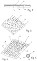
- FIG. 1 shows a workpiece treatment device 1, which has a transport device 2.
- the transport device 2 has a fixed position Document 3 and a relative to the document moving means of transport 4, which as Conveyor belt 5 is formed.
- the conveyor belt 5 is designed as an endless loop 6 and is around Deflection cylinder 7 out, so that there is an upper Run 8 and a lower run 9 results.
- a Drive device By means of a Drive device, not shown, will Conveyor belt 5 in circulation in the direction of Arrow 10 moves so that erected on the upper run 8 Workpieces, for example to be dried, painted cans through treatment zones 11, 12 of the Workpiece treatment device 1 transported will.
- a can feed device and a can removal device is - the clarity half-not shown in Figure 1.
- the treatment zones 11 and 12 are by means of a Partition 13 separated from each other, whereby results in a certain isolation.
- the partition 13 forms a joint in this embodiment 40.
- the strand 8 is on the entrance and exit side Workpiece locks assigned (not shown).
- the treatment zone 11 is a heating fan 14 and the treatment zone 12, a heating fan 15 assigned.
- the heater fan 14 blows in the above space 16 of the transport device 2 the treatment zone 11 hot air (arrow 17), the the transport device 2 passes and into one space located below the transport device 2 18 occurs, from which it goes back to the heater fan 14 is returned. There is therefore a recirculation mode in front.
- the conveyor belt 5 has one Base body 19 on the underside 20 with a sliding plastic coating 21 is provided.
- this sliding plastic coating 21 also on the top of the base body 19 is located, that is, this Base body 19 on all sides with the sliding plastic coating 21 is provided.
- the sliding plastic coating 21 is the conveyor belt 5 of the pad 3, that is, the pad 3 supports the conveyor belt 5 so that it is level Forms surface on which workpieces are securely parked and can be transported.
- the conveyor belt 5 according to FIG. 3 holes 22 which result in air permeability to lead.
- the conveyor belt 5 is thus formed as a perforated band 23.
- Any configurations, which cause air permeability, are the subject of the invention, the holes 22nd or the like are always designed such that the sliding plastic coating 21 also has an air permeability owns.
- FIG 4 is the top view of a transport device 2 shown according to the invention, at the conveyor belt 5 is formed as a network belt 24 is that led over the stationary base 3 becomes. So that of the fan heater 14 and 15 on the transport device 2 directed hot air Transport device 2 can penetrate are in the stationary base 3 vacuum openings 25 and Slits incorporated.
- This arrangement the vacuum openings 25 leads in the design the document 3 as a continuous, that means uninterrupted or several Divide existing document 3 into a good one Stability of objects to be transported.
- the vacuum openings 25 for a pad 3 which consists of several pad parts 41 exists, will be described in more detail below received (see Figures 6 and 7).
- the in Figure 4 shown configuration of the network band 24 exists of webs 26 arranged at right angles, from which the individual stitches 27 of the net band 24 are formed. It is important to ensure that the dimensions of the mesh 27 smaller than the dimensions of the items to be dried are the placed on the mesh belt 24 and through the workpiece treatment device 1 can be transported.
- the net tape 24 can be made of plastic, for example be made from aramid fibers with polytetrafluoroethylene are coated.
- Figure 5 is the cross section of such Web 26 shown, which consists of a web core 28th consists of a layer 29 of polytetrafluoroethylene having.
- FIG. 6 shows a partial section of a base 3 shown, the individual in this embodiment Has underlay parts 41, each one have folded sheet 42.
- the folded sheet 42 has a U-shaped contour, with both legs 43 of each pad part 41 (in FIG. 6) only one leg 43 of the two base parts 41) each represent side walls 44.
- the side walls 44 each go over an edge 45 into an intermediate section 46 Ceiling 47 over.
- the folds 45 form the Transition from side wall 44 to ceiling 47 a bending radius 48 out.
- the side walls 44 of each pad member 41 run parallel to each other and transverse to the direction of transport.
- the blanket 47 of everyone Document part 41 of the document 3 can be in divide three zones.
- the first zone 51 the also includes the vacuum-free zone 50 Vacuum openings 52.
- the vacuum openings 52 are in each of the two border areas Fugue 49 (same as the first zone 51) arranged.
- the vacuum openings 25 are in the second zone 53 of the ceiling 47, the second zone 53 between two first zones 51 one each document section 38.
- the last, third zone 54 is solely from the Joint 49 or joint 40 formed.
- the third zone 54 forms the vacuum-free or reduced pressure zone 50.
- the first Zone 51 overlaps or contains the third zone 54.
- each document section 38 that of the Cover 47 of the respective support part 41 is formed is assigned a suction chamber 55, which with the respective vacuum openings 25, 52 communicating communicates.
- False air flow channel 56 here means that the Effect of negative pressure in the suction chambers 55 in Area of the joints 40 partially dismantled becomes.
- vacuum openings 52 are provided have a larger free cross section, so that the leakage is compensated by increased suction becomes.
- the required hole pattern of the vacuum openings 52 in the first zone 51 is aligned according to the size of the cans to be transported, the Mesh geometry of the conveyor belt 5 and the geometry of the false air flow channel 56 in connection with the for stability reasons respectively drying technical reasons sought specific hot air volume flow through the ribbon.
- the arrangement and design of the vacuum openings 25 in the second zone 53 is aligned also according to the size of the cans to be transported and from the desired pressure drop Hot air flow to generate the necessary negative pressure under the conveyor belt 5, the blockage through the webs 26 of the net band 24 in the worst overlap position is.
- the size is respectively Arrangement of the vacuum openings 25 in the second Zone 53 or the vacuum openings 52 in the first zone 51 not only to that in FIG. 6 shown example limited, but the free one Cross section of the vacuum openings 25 and 52 in the respective zones 51, 53 can be different be designed.
- the effective free cross section on the cans to be transported in the first Zone 51 is larger than the effective cross section of the Vacuum openings 25 in the area of the second zone 53 um, as already mentioned, the leakage in the third zone 54 to compensate.
- each Vacuum openings 25, 52 paid attention to be that the size of the openings at least so be chosen large that a single opening not all or most of a web 26 of the Net tape 24, which is shown in Figure 4, covered can be.
- the opening size is also capped, as the size of the Opening with the same free cross section of the Opening distance, that is, the division chosen larger must become. This is again due to the can footprint limited to each other Time when it passes through on the conveyor belt 5 standing doses through the individual treatment zones 11, 12 a sufficient number of vacuum openings 25, 52 are below the can have to.
- the conveyor belt 5 is in FIG Not shown for clarity.
- Circles 57 shown in Figure 7 cans to be transported.
- Circles 57 shown.
- the circle 57 preferably always covers four vacuum openings 25. This makes so much Extracted hot air that the necessary vacuum under the can even when blocked by the Conveyor belt 5 is built.
- the peripheral position shows that the circle 57 only the vacuum openings 52 in the ceiling 47 of the right document section 38, a small number of vacuum openings 25 and covers a portion of the joint 40.
- circle 57 does not cover the vacuum openings 52 in the ceiling 47 of the left document section 38. Due to the larger cross-section of the vacuum openings 52 in the first Zone 51 becomes the false air flow channel 56 in the junction 40 by the increased flow rate caught or compensated. Will the Vacuum openings 52 and the vacuum openings 25 closer to each other than the division of the Corresponds to vacuum openings 25 in the second zone 53, which further increases the free cross section further improvement can be achieved will.
Landscapes
- Engineering & Computer Science (AREA)
- Mechanical Engineering (AREA)
- General Engineering & Computer Science (AREA)
- Textile Engineering (AREA)
- Drying Of Solid Materials (AREA)
- Belt Conveyors (AREA)
- Feeding Of Workpieces (AREA)
Description
- Figur 1
- eine schematische Ansicht einer Werkstück-Behandlungsvorrichtung,
- Figur 2
- einen Schnitt durch eine Transporteinrichtung,
- Figur 3
- einen Ausschnitt aus einem Transportband der Transporteinrichtung,
- Figur 4
- ein weiteres Ausführungsbeispiel einer als Netz ausgebildeten Transporteinrichtung mit gelöcherter Unterlage,
- Figur 5
- einen Querschnitt durch einen die Maschen des Netzbandes der Figur 4 bildenden Steg,
- Figur 6
- eine perspektivische Ansicht auf eine Unterlage einer Transporteinrichtung und
- Figur 7
- eine Draufsicht auf die Unterlage einer erfindungsgemäßen Transporteinrichtung.
Claims (10)
- Trocknungsvorrichtung mit einer Transporteinrichtung (2) in Gestalt eines Bandförderers (8, 9) für zu behandelnde Werkstücke, insbesondere für die Trocknung von lackierten oder bedruckten Dosen, wobei die Transporteinrichtung (2) ein sich entlang einer ortsfesten Anlage bewegendes, als luftdurchlässiges Transportband (5) ausgebildetes Transportmittel für die Werkstücke aufweist und die Anlage luftdurchlässig ist, insbesondere mit Löchern oder Schlitzen versehen ist, dadurch gekennzeichnet, daß das Transportband (5) ein Netzband (24) aus Aramid-Fasern ist und daß die Anlage dessen Unterlage (3) ist.
- Trocknungsvorrichtung nach Anspruch 1, dadurch gekennzeichnet, daß die Unterlage (3) und/oder das Transportmittel (4) eine Gleitkunststoffbeschichtung, insbesondere aus Polytetrafluorethylen (PTFE), aufweist.
- Trocknungsvorrichtung nach einem der vorhergehenden Ansprüche, dadurch gekennzeichnet, daß die Unterdrucköffnungen (52) aufweisende Unterlage (3) aus mindestens zwei aneinanderstoßenden Unterlagenabschnitten (38) besteht und daß in der Zone (erste Zone 51) der Stoßstelle (40) der auf das jeweilige Werkstück dort wirkende Querschnitt (Randlochungsquerschnitt) der Unterdrucköffnungen (52) größer als der wirkende Querschnitt (Normallochungsquerschnitt) in den übrigen Zonen (zweite Zone 53) der Unterlage (3) ist.
- Trocknungsvorrichtung nach Anspruch 3, dadurch gekennzeichnet, daß der Randlochungsquerschnitt von einer erhöhten Anzahl von Unterdrucköffnungen (52) in der ersten Zone (51) gegenüber der Anzahl der Unterdrucköffnungen (25) in der zweiten Zone (53) gebildet wird.
- Trocknungsvorrichtung nach einem der vorhergehenden Ansprüche 3 oder 4, dadurch gekennzeichnet, daß zumindest einige der Unterdrucköffnungen (52) in der ersten Zone (51) jeweils einen kleineren Querschnitt als die oder einige der Unterdrucköffnungen (25) in der zweiten Zone (53) aufweisen.
- Trocknungsvorrichtung nach einem der vorhergehenden Ansprüche 3 bis 5, dadurch gekennzeichnet, daß jedem Unterlagenabschnitt eine separate, mit den zugehörigen Unterdrucköffnungen (25, 52) kommunizierende Saugkammer (55) zugeordnet ist.
- Trocknungsvorrichtung nach einem der vorhergehenden Ansprüche 3 bis 6, dadurch gekennzeichnet, daß die Stoßstelle (40) eine unterdruckfreie beziehungsweise unterdruckreduzierte dritte Zone (54) bildet.
- Trocknungsvorrichtung nach einem der vorhergehenden Ansprüche 3 bis 7, dadurch gekennzeichnet, daß jeder Unterlagenabschnitt (38) von der Decke (47) eines kastenartig ausgebildeten Unterlagenteiles (41), insbesondere Saugkastens, gebildet ist.
- Trocknungsvorrichtung nach Anspruch 8, dadurch gekennzeichnet, daß jedes Unterlagenteil (41) ein vorzugsweise gekantetes Blech (42) aufweist, das zwei Seitenwände (44) bildende Schenkel (43) und einen die Decke (47) bildenden Zwischenabschnitt (46) aufweist, wobei die Seitenwände (44) über Kantungen (45) in die Decke (47) übergehen und daß die Längserstreckung der Kantungen (45) quer zur Transportrichtung verlaufen.
- Trocknungsvorrichtung nach einem der vorhergehenden Ansprüche 3 bis 9, dadurch gekennzeichnet, daß die Anordnung der Unterdrucköffnungen (25, 52) und/oder ihr Querschnitt und der lochfreie Bereich des Transportbandes (5), derart aufeinander abgestimmt sind, daß einer Standfläche eines Gegenstandes mindestens eine nicht abgedeckte Unterdrucköffnung (25, 52) oder ein hinreichend großer Bereich dieser Unterdrucköffnungen (25, 52) für das standsichere Halten des Werkstücks zugeordnet ist.
Applications Claiming Priority (4)
| Application Number | Priority Date | Filing Date | Title |
|---|---|---|---|
| DE19944404307 DE4404307C1 (de) | 1994-02-11 | 1994-02-11 | Trocknungsvorrichtung |
| DE4404307 | 1994-02-11 | ||
| DE4440926A DE4440926C2 (de) | 1994-02-11 | 1994-11-17 | Werkstück-Behandlungsvorrichtung |
| DE4440926 | 1994-11-17 |
Publications (2)
| Publication Number | Publication Date |
|---|---|
| EP0667309A1 EP0667309A1 (de) | 1995-08-16 |
| EP0667309B1 true EP0667309B1 (de) | 1998-10-28 |
Family
ID=25933721
Family Applications (1)
| Application Number | Title | Priority Date | Filing Date |
|---|---|---|---|
| EP95101461A Expired - Lifetime EP0667309B1 (de) | 1994-02-11 | 1995-02-03 | Werkstück-Behandlungsvorrichtung |
Country Status (3)
| Country | Link |
|---|---|
| US (1) | US5595282A (de) |
| EP (1) | EP0667309B1 (de) |
| JP (1) | JPH07257722A (de) |
Families Citing this family (7)
| Publication number | Priority date | Publication date | Assignee | Title |
|---|---|---|---|---|
| AU4112297A (en) * | 1996-09-03 | 1998-03-26 | Niro A/S | Process and apparatus for spray drying or spray cooling |
| US6547057B1 (en) * | 2000-06-05 | 2003-04-15 | Cbw Automation, Inc. | Apparatus and process for handling circular articles |
| US6575450B2 (en) | 2001-01-30 | 2003-06-10 | Lockheed Martin Corporation | Singulation mechanism |
| DK1684916T3 (da) | 2003-11-18 | 2013-06-10 | Habasit Ag | Plasmacoatet transportbånd |
| GB0411661D0 (en) * | 2004-05-25 | 2004-06-30 | Greenbank Technology Ltd | Drying apparatus and method |
| RU2351522C1 (ru) * | 2007-08-15 | 2009-04-10 | Виталий Александрович Минькин | Устройство для перемещения штучных хлебобулочных изделий (варианты) |
| KR102400252B1 (ko) * | 2020-01-07 | 2022-05-19 | 장활석 | 스틸벨트형 이송컨베이어 |
Family Cites Families (20)
| Publication number | Priority date | Publication date | Assignee | Title |
|---|---|---|---|---|
| US1278537A (en) * | 1918-03-02 | 1918-09-10 | Ferdinand M Wegner | Fur-shearing machine and fur-unhairing machine. |
| US2813637A (en) * | 1952-06-24 | 1957-11-19 | Johns Manville | Shingle take off and stacker |
| US3096162A (en) * | 1958-02-19 | 1963-07-02 | Spooner Dryer & Eng Co Ltd | Gaseous restraint of conveyed articles |
| US3202302A (en) * | 1962-06-20 | 1965-08-24 | Saint Gobain Corp | Vacuum transfer conveyor |
| NL6605291A (de) * | 1965-06-24 | 1966-12-27 | ||
| GB1341095A (en) * | 1970-06-09 | 1973-12-19 | Midland Ross Corp | Conveyor system |
| DE7514476U (de) * | 1975-05-06 | 1976-02-26 | Ab Svenska Flaektfabriken, Nacka (Schweden) | Transportoer fuer plattenfoermiges material |
| DE3001531A1 (de) * | 1980-01-17 | 1981-07-23 | Continental Gummi-Werke Ag, 3000 Hannover | Foerdergurt |
| JPS59156013U (ja) * | 1983-04-06 | 1984-10-19 | 東レ・モノフイラメント株式会社 | コンベアベルト |
| ZA856945B (en) * | 1984-10-22 | 1986-06-25 | Precision Metal Fab | Curved vacuum transfer conveyor |
| US4768643A (en) * | 1985-02-12 | 1988-09-06 | Meyer Conveyair, Inc. | Guide rail and deadplate alignment device for flexible wall container vacuum transfer |
| EP0206985B1 (de) * | 1985-06-26 | 1989-03-29 | SIG Schweizerische Industrie-Gesellschaft | Vorrichtung zum Vereinzeln von aneinander anliegenden Einzelstücken |
| JPH0512170Y2 (de) * | 1988-07-27 | 1993-03-29 | ||
| JPH0617771Y2 (ja) * | 1988-11-16 | 1994-05-11 | 本多産業株式会社 | 蛇行防止コンベアベルトのガイド体 |
| JP2505273Y2 (ja) * | 1990-01-26 | 1996-07-24 | 池上通信機株式会社 | 被検体搬送装置 |
| DE4005349A1 (de) * | 1990-02-20 | 1991-08-22 | Franz Schoerghuber | Vorrichtung zum festhalten und foerdern von platten |
| DE4013302A1 (de) * | 1990-04-26 | 1991-10-31 | Koenig & Bauer Ag | Vorrichtung zum foerdern eines insbesondere geschuppten stroms von bogen |
| JPH064958Y2 (ja) * | 1990-06-26 | 1994-02-09 | ロザイ工業株式会社 | 缶の連続洗浄装置 |
| JPH07215432A (ja) * | 1994-01-31 | 1995-08-15 | Kawasaki Steel Corp | 真空吸引コンベヤ |
| US5373933A (en) * | 1993-11-09 | 1994-12-20 | Tomra Systems A/S | Conveyor with variable suction force |
-
1994
- 1994-12-28 US US08/365,612 patent/US5595282A/en not_active Expired - Fee Related
-
1995
- 1995-02-03 EP EP95101461A patent/EP0667309B1/de not_active Expired - Lifetime
- 1995-02-10 JP JP7023128A patent/JPH07257722A/ja active Pending
Also Published As
| Publication number | Publication date |
|---|---|
| US5595282A (en) | 1997-01-21 |
| EP0667309A1 (de) | 1995-08-16 |
| JPH07257722A (ja) | 1995-10-09 |
Similar Documents
| Publication | Publication Date | Title |
|---|---|---|
| EP0465769B1 (de) | Vorrichtung zum durchströmenden Behandeln von bahnförmigem Gut | |
| EP0818568A2 (de) | Verfahren und Vorrichtung zum hydrodynamischen Verschlingen der Fasern einer Faserbahn | |
| EP1039006A1 (de) | Verfahren und Vorrichtung zur Herstellung von perforierten Vliesstoffen mittels hydrodynamischer Vernadelung | |
| EP0841424B1 (de) | Vorrichtung zum hydrodynamischen Vernadeln von Vliesen, Tissue od. dgl. | |
| DE19922165C2 (de) | Trockner für band- oder plattenförmiges Gut | |
| DE1635096B2 (de) | Daempfer zum kontinuierlichen fixieren von textilien | |
| DE2458455C2 (de) | Vorrichtung zum Trocknen einer sich bewegenden Materialbahn | |
| DE3036669C2 (de) | ||
| DE69908697T2 (de) | Wellpappenmaschine mit einem mit polymeren Harzmaterial beschichtetem Gurt | |
| EP0175900B1 (de) | Bügelwalze, insbesondere für den Wäschereibetrieb | |
| DE69921190T2 (de) | Siebnetz zur verteilung von fasern | |
| DE2918833C2 (de) | Vorrichtung zum Trocknen und Krumpfen von textiler Maschenware | |
| EP0472072A1 (de) | Drahtgliederband | |
| DE4440926C2 (de) | Werkstück-Behandlungsvorrichtung | |
| EP0667309A1 (de) | Werkstück-Behandlungsvorrichtung | |
| EP1184175A1 (de) | Bogentransportzylinder | |
| DE69834186T2 (de) | Zellulosebahn, verfahren und vorrichtung zu seiner herstellung mittels eines papiermacherbandes mit schräger querschnittsstruktur, und verfahren zur herstellungdes bandes | |
| DE60013741T2 (de) | Elastisch dehnbare mehrschichtige Tuchlage und Verfahren zu ihrer Herstellung | |
| DE3735709C2 (de) | Papiermaschinenband | |
| DE2731269C2 (de) | Faservlies sowie Verfahren und Vorrichtung zur Herstellung des Vlieses | |
| DE3220076A1 (de) | Luftblaskasten fuer die trockenpartie einer papiermaschine | |
| EP0440076B1 (de) | Pressfilz | |
| DE1913261A1 (de) | Vorrichtung zum Trocknen bahnfoermigen Materials | |
| EP0192207B1 (de) | Furniertrockner für Messerfurniere | |
| DE2115640C3 (de) | Trocknungsanlage zum trocknen von einseitig offenen behaeltern, z.b. dosen |
Legal Events
| Date | Code | Title | Description |
|---|---|---|---|
| PUAI | Public reference made under article 153(3) epc to a published international application that has entered the european phase |
Free format text: ORIGINAL CODE: 0009012 |
|
| AK | Designated contracting states |
Kind code of ref document: A1 Designated state(s): FR GB IT NL |
|
| 17P | Request for examination filed |
Effective date: 19950722 |
|
| 17Q | First examination report despatched |
Effective date: 19960708 |
|
| GRAG | Despatch of communication of intention to grant |
Free format text: ORIGINAL CODE: EPIDOS AGRA |
|
| GRAG | Despatch of communication of intention to grant |
Free format text: ORIGINAL CODE: EPIDOS AGRA |
|
| GRAH | Despatch of communication of intention to grant a patent |
Free format text: ORIGINAL CODE: EPIDOS IGRA |
|
| GRAH | Despatch of communication of intention to grant a patent |
Free format text: ORIGINAL CODE: EPIDOS IGRA |
|
| GRAA | (expected) grant |
Free format text: ORIGINAL CODE: 0009210 |
|
| AK | Designated contracting states |
Kind code of ref document: B1 Designated state(s): FR GB IT NL |
|
| GBT | Gb: translation of ep patent filed (gb section 77(6)(a)/1977) |
Effective date: 19981204 |
|
| ET | Fr: translation filed | ||
| PLBE | No opposition filed within time limit |
Free format text: ORIGINAL CODE: 0009261 |
|
| STAA | Information on the status of an ep patent application or granted ep patent |
Free format text: STATUS: NO OPPOSITION FILED WITHIN TIME LIMIT |
|
| 26N | No opposition filed | ||
| PGFP | Annual fee paid to national office [announced via postgrant information from national office to epo] |
Ref country code: FR Payment date: 20000112 Year of fee payment: 6 |
|
| PGFP | Annual fee paid to national office [announced via postgrant information from national office to epo] |
Ref country code: NL Payment date: 20000117 Year of fee payment: 6 |
|
| PGFP | Annual fee paid to national office [announced via postgrant information from national office to epo] |
Ref country code: GB Payment date: 20000120 Year of fee payment: 6 |
|
| PG25 | Lapsed in a contracting state [announced via postgrant information from national office to epo] |
Ref country code: GB Free format text: LAPSE BECAUSE OF NON-PAYMENT OF DUE FEES Effective date: 20010203 |
|
| PG25 | Lapsed in a contracting state [announced via postgrant information from national office to epo] |
Ref country code: NL Free format text: LAPSE BECAUSE OF NON-PAYMENT OF DUE FEES Effective date: 20010901 |
|
| GBPC | Gb: european patent ceased through non-payment of renewal fee |
Effective date: 20010203 |
|
| PG25 | Lapsed in a contracting state [announced via postgrant information from national office to epo] |
Ref country code: FR Free format text: LAPSE BECAUSE OF NON-PAYMENT OF DUE FEES Effective date: 20011031 |
|
| NLV4 | Nl: lapsed or anulled due to non-payment of the annual fee |
Effective date: 20010901 |
|
| REG | Reference to a national code |
Ref country code: FR Ref legal event code: ST |
|
| PG25 | Lapsed in a contracting state [announced via postgrant information from national office to epo] |
Ref country code: IT Free format text: LAPSE BECAUSE OF NON-PAYMENT OF DUE FEES;WARNING: LAPSES OF ITALIAN PATENTS WITH EFFECTIVE DATE BEFORE 2007 MAY HAVE OCCURRED AT ANY TIME BEFORE 2007. THE CORRECT EFFECTIVE DATE MAY BE DIFFERENT FROM THE ONE RECORDED. Effective date: 20050203 |