EP0665098B1 - Luftreifen - Google Patents
Luftreifen Download PDFInfo
- Publication number
- EP0665098B1 EP0665098B1 EP95104921A EP95104921A EP0665098B1 EP 0665098 B1 EP0665098 B1 EP 0665098B1 EP 95104921 A EP95104921 A EP 95104921A EP 95104921 A EP95104921 A EP 95104921A EP 0665098 B1 EP0665098 B1 EP 0665098B1
- Authority
- EP
- European Patent Office
- Prior art keywords
- mold
- elements
- sheets
- tyre
- tread
- Prior art date
- Legal status (The legal status is an assumption and is not a legal conclusion. Google has not performed a legal analysis and makes no representation as to the accuracy of the status listed.)
- Expired - Lifetime
Links
- 238000000465 moulding Methods 0.000 abstract description 21
- 230000007246 mechanism Effects 0.000 abstract 1
- 230000035945 sensitivity Effects 0.000 abstract 1
- 230000002093 peripheral effect Effects 0.000 description 8
- 230000007547 defect Effects 0.000 description 5
- 238000004073 vulcanization Methods 0.000 description 4
- 238000006243 chemical reaction Methods 0.000 description 3
- 238000013459 approach Methods 0.000 description 2
- 230000001186 cumulative effect Effects 0.000 description 2
- 230000007423 decrease Effects 0.000 description 2
- 238000013461 design Methods 0.000 description 2
- 238000011161 development Methods 0.000 description 2
- 230000000694 effects Effects 0.000 description 2
- 238000012423 maintenance Methods 0.000 description 2
- 238000003892 spreading Methods 0.000 description 2
- 241000237536 Mytilus edulis Species 0.000 description 1
- 229910000831 Steel Inorganic materials 0.000 description 1
- 238000005452 bending Methods 0.000 description 1
- 230000008602 contraction Effects 0.000 description 1
- 238000005520 cutting process Methods 0.000 description 1
- 230000003247 decreasing effect Effects 0.000 description 1
- 230000010339 dilation Effects 0.000 description 1
- 238000005516 engineering process Methods 0.000 description 1
- 238000000605 extraction Methods 0.000 description 1
- 238000004519 manufacturing process Methods 0.000 description 1
- 239000012528 membrane Substances 0.000 description 1
- 239000002184 metal Substances 0.000 description 1
- 238000000034 method Methods 0.000 description 1
- 239000000203 mixture Substances 0.000 description 1
- 235000020638 mussel Nutrition 0.000 description 1
- 230000035515 penetration Effects 0.000 description 1
- 238000003825 pressing Methods 0.000 description 1
- 230000001846 repelling effect Effects 0.000 description 1
- 230000000284 resting effect Effects 0.000 description 1
- 238000005096 rolling process Methods 0.000 description 1
- 239000010959 steel Substances 0.000 description 1
- 238000005728 strengthening Methods 0.000 description 1
Images

Classifications
-
- B—PERFORMING OPERATIONS; TRANSPORTING
- B60—VEHICLES IN GENERAL
- B60C—VEHICLE TYRES; TYRE INFLATION; TYRE CHANGING; CONNECTING VALVES TO INFLATABLE ELASTIC BODIES IN GENERAL; DEVICES OR ARRANGEMENTS RELATED TO TYRES
- B60C11/00—Tyre tread bands; Tread patterns; Anti-skid inserts
- B60C11/03—Tread patterns
- B60C11/0306—Patterns comprising block rows or discontinuous ribs
-
- B—PERFORMING OPERATIONS; TRANSPORTING
- B29—WORKING OF PLASTICS; WORKING OF SUBSTANCES IN A PLASTIC STATE IN GENERAL
- B29C—SHAPING OR JOINING OF PLASTICS; SHAPING OF MATERIAL IN A PLASTIC STATE, NOT OTHERWISE PROVIDED FOR; AFTER-TREATMENT OF THE SHAPED PRODUCTS, e.g. REPAIRING
- B29C33/00—Moulds or cores; Details thereof or accessories therefor
- B29C33/30—Mounting, exchanging or centering
- B29C33/301—Modular mould systems [MMS], i.e. moulds built up by stacking mould elements, e.g. plates, blocks, rods
- B29C33/302—Assembling a large number of mould elements to constitute one cavity
-
- B—PERFORMING OPERATIONS; TRANSPORTING
- B29—WORKING OF PLASTICS; WORKING OF SUBSTANCES IN A PLASTIC STATE IN GENERAL
- B29D—PRODUCING PARTICULAR ARTICLES FROM PLASTICS OR FROM SUBSTANCES IN A PLASTIC STATE
- B29D30/00—Producing pneumatic or solid tyres or parts thereof
- B29D30/06—Pneumatic tyres or parts thereof (e.g. produced by casting, moulding, compression moulding, injection moulding, centrifugal casting)
- B29D30/0601—Vulcanising tyres; Vulcanising presses for tyres
- B29D30/0606—Vulcanising moulds not integral with vulcanising presses
- B29D30/0629—Vulcanising moulds not integral with vulcanising presses with radially movable sectors
-
- B—PERFORMING OPERATIONS; TRANSPORTING
- B60—VEHICLES IN GENERAL
- B60C—VEHICLE TYRES; TYRE INFLATION; TYRE CHANGING; CONNECTING VALVES TO INFLATABLE ELASTIC BODIES IN GENERAL; DEVICES OR ARRANGEMENTS RELATED TO TYRES
- B60C11/00—Tyre tread bands; Tread patterns; Anti-skid inserts
-
- B—PERFORMING OPERATIONS; TRANSPORTING
- B29—WORKING OF PLASTICS; WORKING OF SUBSTANCES IN A PLASTIC STATE IN GENERAL
- B29D—PRODUCING PARTICULAR ARTICLES FROM PLASTICS OR FROM SUBSTANCES IN A PLASTIC STATE
- B29D30/00—Producing pneumatic or solid tyres or parts thereof
- B29D30/06—Pneumatic tyres or parts thereof (e.g. produced by casting, moulding, compression moulding, injection moulding, centrifugal casting)
- B29D30/0601—Vulcanising tyres; Vulcanising presses for tyres
- B29D30/0606—Vulcanising moulds not integral with vulcanising presses
- B29D2030/0607—Constructional features of the moulds
- B29D2030/0609—Constructional features of the moulds the moulds being made of a plurality of laminations, e.g. thin plates, adjacent one another, so as to create the moulding cavity
-
- B—PERFORMING OPERATIONS; TRANSPORTING
- B29—WORKING OF PLASTICS; WORKING OF SUBSTANCES IN A PLASTIC STATE IN GENERAL
- B29D—PRODUCING PARTICULAR ARTICLES FROM PLASTICS OR FROM SUBSTANCES IN A PLASTIC STATE
- B29D30/00—Producing pneumatic or solid tyres or parts thereof
- B29D30/06—Pneumatic tyres or parts thereof (e.g. produced by casting, moulding, compression moulding, injection moulding, centrifugal casting)
- B29D30/0601—Vulcanising tyres; Vulcanising presses for tyres
- B29D30/0606—Vulcanising moulds not integral with vulcanising presses
- B29D2030/0607—Constructional features of the moulds
- B29D2030/0612—Means for forming recesses or protrusions in the tyres, e.g. grooves or ribs, to create the tread or sidewalls patterns
-
- B—PERFORMING OPERATIONS; TRANSPORTING
- B29—WORKING OF PLASTICS; WORKING OF SUBSTANCES IN A PLASTIC STATE IN GENERAL
- B29D—PRODUCING PARTICULAR ARTICLES FROM PLASTICS OR FROM SUBSTANCES IN A PLASTIC STATE
- B29D30/00—Producing pneumatic or solid tyres or parts thereof
- B29D30/06—Pneumatic tyres or parts thereof (e.g. produced by casting, moulding, compression moulding, injection moulding, centrifugal casting)
- B29D30/0601—Vulcanising tyres; Vulcanising presses for tyres
- B29D30/0606—Vulcanising moulds not integral with vulcanising presses
- B29D30/0629—Vulcanising moulds not integral with vulcanising presses with radially movable sectors
- B29D2030/063—Vulcanising moulds not integral with vulcanising presses with radially movable sectors the moulds being split in upper and lower halves
-
- B—PERFORMING OPERATIONS; TRANSPORTING
- B29—WORKING OF PLASTICS; WORKING OF SUBSTANCES IN A PLASTIC STATE IN GENERAL
- B29L—INDEXING SCHEME ASSOCIATED WITH SUBCLASS B29C, RELATING TO PARTICULAR ARTICLES
- B29L2030/00—Pneumatic or solid tyres or parts thereof
Definitions
- Molding of tires in particular of the tread rolling of these, must satisfy a set of binding conditions.
- Patent application EP 0 242 840 describes a mold completely rigid with a peripheral crown of sectors to mold the tread, two shells side to mold the sides (external surfaces of the pneumatic) and a rigid core to mold the surface inside of the tire.
- the totally rigid design of this mold brings many advantages as to the quality of the molded tire because the geometric shapes obtained are of high quality (excellent circularity, in all transverse position).
- imposed volume molding requires very close tolerances on volume of the raw tire blank.
- An object of the invention is to retain the advantage of rigid mold from the point of view of respect and perfect control of the geometric quality of the tires produced with this type of mold, while making the molding operation less sensitive to volume fluctuations of raw blanks tires for molding and vulcanizing.
- Simplification of opening and closing kinematics closing of the molds, and therefore the simplification of vulcanization presses is another objective of the invention.
- a tire according to claim 1 is, in particular, manufactured by mold with two shells for the molding from the outside of the sides, and a crown device for molding the outside of the strip bearing, said crown being formed by stacking in the direction circumferential of a plurality of adjacent elements of thin, oriented substantially radially.
- each element rests on the two adjacent elements to ensure a kind of elastic repulsion of the elements relative to others in the circumferential direction.
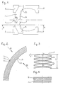
- the peripheral crown tread molding consists of a multitude of adjacent sheets 1, arranged so that the approach movement (molding) and backward movement (demolding), which is done in the plane of the sheet, that is to say purely radial in any point on the tire.
- This movement is exactly radial, to the thickness of the sheets, corresponding thickness to the resolution of the mold to define the sculpture.
- We for example uses steel sheets; they are cut out according to the patterns of sculpture 5 which must be produced.
- the sheets 1 are arranged radially.
- the sheets are arranged so as to understand a radius, i.e. at an angle 90 ° to use the usual terminology for characterize the path of the cables in the tire.
- the elements are arranged at an angle slightly different from 90 °, spreading for example of the order of 10 ° to 15 °.
- Each sheet is cut so that its edge 10 ensures the molding of the sculpture. All common items sculptures, including slats, can be obtained in this way.
- each of the adjacent elements constituting the crown rests on the two elements neighbors so that the support reactions tend in constantly repelling the elements by adding to other.
- each element here, each sheet 1 is deformed so as to increase its size E in the direction circumferential, relative to its thickness e, and to the state free from all constraints.
- FIG. 3 provides a good understanding of how sheets 1 are deformed, for example by bending or stamping, representing the shape of the crown device, seen from outside the mold, in position opening hours.
- Each element 1 has a thickness comprised of preferably between 1% and 5% of its measured length parallel to the axis of the mold.
- sheet thickness e used will vary from 0.1 mm to 5 mm. She is in any case much smaller than the size of the sculpture step.
- Said deformations of the two adjacent elements are out of phase so that stacking of the elements on top of each other others reach a cumulative length L close to or equal to the sum of dimensions E. We can also stack successively deformed elements by inserting each times an undistorted element.
- the deformations of two adjacent elements can be opposite to each other, as illustrated by Figure 3, or develop perpendicular to each other compared to others or in any other way that leads adjacent elements not to stick to each other over their entire surface.
- All the sheets 1 are threaded on a belt 4 formed by a profile whose ends can penetrate into each other to form a ring of freely variable diameter.
- This belt only plays maintenance role, and does not play a direct role in the kinematics of closing and opening of the mold.
- This belt must not introduce any friction likely to cause tangential movements of the sheets 1.
- the closing of the mold is caused by the movement of frets conical 3, movable parallel to the axis of the mold.
- the angle that forms the conical surface is of course chosen for be non-cornering.
- the opening of the mold is authorized by the spacing of the frets 3, and caused by the sheets themselves, by elastic return to a configuration as illustrated in Figure 3, while in the position of closing, the sheets are all joined at least on the side interior, as shown in Figure 4.
- the transverse curvature of the tread of the tire can sometimes be quite significant.
- the game between 1 adjacent sheets can therefore be canceled on either side of the tread at the locations marked 11 in FIG. 1, while there is still a play in the middle part.
- the sufficiently weak playing condition must also be verified at the level of the median plane, and when the sheets will penetrate into the rubber, that is to say well before the closed position of the mold. If at this point we finds that the clearance between sheets is too large, it is necessary increase the number of sheets to decrease due to competition each game, and / or use sheets of which at least the end of the molding edge side 10 has a thickness gradually decreasing, to form a slight wedge. In in this case it is possible to have substantially the same clearance between sheets all along the molding section 10.
- the sheets can be shaped so that leave a non-rectilinear trace in a view such as that of figure 4, for example to follow the pace of certain slats.
- the sheets are all conformed to the same way and are stacked so as to phase the conformations, unlike sheet deformations intended to cause elastic recoil, or to defects in flatness, which are arranged to rest on each other the others as explained above. This illustrates that the conformation in question here responds to another function that the deformation or the flatness defects having a specific role as described.
- the sheets can also be arranged at an angle slightly different from 90 ° from the median plane of the mold, which can be seen in Figure 4 (center line). We can accommodate a deviation of around 10 ° to 15 ° from the right angle. But in no case can we arrange the sheets perpendicular to the axis of the mold, or at a slight angle to the plane perpendicular to the axis of the mold, on pain of having no more reminder elastic towards the expanded position.
- the sheets must be arranged transversely, i.e. from one shoulder and be oriented towards the other shoulder of the tire to be molded.
- FIG. 5 illustrates another mold in which we divided the peripheral crown in two parts G and D. This therefore comprises, transversely, two distinct elements 1D and 1G adjacent, each belonging to one of the parties, each having an edge 18 intended to come into contact on the other part with the corresponding edge 18 of the element adjacent to said other part.
- a tire according to claim 2 is especially produced in this type of mold.
- This kind of mold is commonly referred to as the designation "in two parts", which separate in two substantially identical axial halves when opened necessary for demolding.
- the mold in its two-part version allows you to combine the largest simplicity of the two-part mold with the capacity opening by radial recoil of the elements which move away radially from the axis of the mold.
- the mold includes means for command and control the forward and backward movement elements of one of the parts of the crown through movement in axial direction of the shell 2 adjacent.
- Each shell 2 has a groove 20 in which the lateral end 13 of each element 1D or 1G is engaged.
- the radially upper surface 21 of said groove 20 is frustoconical, the lateral end 13 of each element 1D and 1G being cut into a shape allowing each element 1D and 1G to be supported on said surface tapered 21.
- the 1D elements lean on each other in the direction circumferential and part D of the crown therefore presents a natural tendency to take the dilated position, which is that of the right part of figure 5. This is obtained as previously explained, either by the flatness defects that each of the 1D elements naturally presents, which are not the same for all elements, either distorting the elements and arranging them judiciously. Of even for 1G elements.
- the upper frustoconical surface 21 is supported on the above 16 of each 1G (or 1D) element.
- the only possible movement of the elements 1G (or 1D), in response to the axial approximation of the shell, is a movement of radial advance towards the position of closing the mold.
- the movement of all 1G elements (or 1D) is of course simultaneous. This explains the closure of the mold.
- the movement of the left shells and right is symmetrical, to avoid any friction of edges 18 on top of each other.
- each part G and D crown rests on the frustoconical surface upper 21. This explains the opening movement of the mold.
- each element has a notch 14, the notches 14 of the elements adjacent being aligned to form on each part of the crowns a circumferential groove containing a ring of support 15 deformable in the peripheral direction for support movements of dilation and / or contraction in diameter of said crown.
- the role of this ring of maintenance 15 is to help maintain the elements 1D and 1G well aligned each in their crown.
- Figure 6 shows that the retaining ring 15 is a split ring, each of which end 150 can slide on the other, to modify freely the development of the ring 15 without interrupting its continuity.
- each element has two notches 19.
- each element comprising a section 17 likely to come in support on said frustoconical bearing 22.
- the lateral end 13 of each 1D and 1G element is cut into a shape corresponding to the meridian radial section of the groove 20. This provides the piston effect between shell and crown, the role of which is described in patent EP 0 242 840.
- frustoconical bearing 230 at the same angle as the frustoconical bearing 22, also oriented radially outwards, each element comprising a slice 170 capable of coming to bear on said frustoconical bearing 230.
- Support of the elements on the tapered surfaces 230 and 22 can help cause radial recoil movement of said elements during opening the mold. These, or some of them, may have a tendency to stick to the tire, a remain embedded in the tread pattern. The lifting effort can therefore come from pressing on the frustoconical bearings 22 and 230, then the natural tendency to the opening of the crown then brings the 1D elements and 1G resting on the frustoconical surface 21.
- a stop 23 is provided on each shell 2. It it is an insert on the frets 3, at the end axial of these, which also includes the range 230 mentioned above. This stop 23 stops the elements 1D and 1G by meeting with the shoulder 12 present on all these. Note that the necessary recoil movement corresponds only at the depth P of sculpture, plus a small stroke additional security. Then the left and right of the mold can dodge completely freely by pure axial movement. This greatly simplifies the vulcanization press receiving this type of mold, and limits the overall dimensions in the radial direction.
- the advantage of using a mold as described combined with a rigid core is that in this case it gives the mold a certain elasticity, that is to say a certain capacity to slightly increase the volume of the mold cavity to follow the expansion of the rubber resulting from the temperature increase, while spreading the clearances between mold parts. This is obtained leaving the shells 2 or more to move axially generally conical frets 3, beyond a certain prevailing pressure in the tire mold cavity.
Landscapes
- Engineering & Computer Science (AREA)
- Mechanical Engineering (AREA)
- Moulds For Moulding Plastics Or The Like (AREA)
- Tires In General (AREA)
- Heating, Cooling, Or Curing Plastics Or The Like In General (AREA)
- Medicines Containing Material From Animals Or Micro-Organisms (AREA)
- Tyre Moulding (AREA)
Claims (4)
- Luftreifen, dessen Lauffläche ein Profil aufweist, das durch eine Oberfläche gebildet ist, die durch eine Gruppe benachbarter Kanten festgelegt ist, die sich von einer Schulter zur anderen Schulter erstrecken, in Umfangsrichtung aufeinanderfolgen und von denen jede Kante durch zwei Spuren begrenzt ist, die an der genannten Oberfläche voneinander durch einen geringen, gegebenen Abstande" getrennt sind, wobei die Oberfläche näherungsweise die Muster des genannten Profils durch stufenweise erfolgende Veränderung festlegt.

- Luftreifen, dessen Lauffläche ein Profil aufweist, das durch eine Oberfläche gebildet ist, die durch zwei Gruppen benachbarter Kanten festgelegt ist, wobei sich die Spuren der ersten Gruppe von einer Schulter zu einer Ebene erstrecken, die im wesentlichen mittig und senkrecht zur Achse des Luftreifens verläuft, sich die Spuren der zweiten Gruppe von der anderen Schulter zur genannten Ebene erstrecken, die im wesentlichen mittig und senkrecht zur Achse des Luftreifens verläuft, die Spuren einer jeden Gruppe in Umfangsrichtung aufeinander folgen, jede Kante durch zwei Spuren begrenzt ist, die an der genannten Oberfläche voneinander durch einen geringen, gegebenen Abstand
- Luftreifen nach Anspruch 1 oder 2, in dem jede Spur in einer Ebene gelegen ist.
- Luftreifen nach einem der Ansprüche 1 bis 3, in dem der genannte Abstand
Applications Claiming Priority (5)
| Application Number | Priority Date | Filing Date | Title |
|---|---|---|---|
| FR9205903A FR2691095A1 (fr) | 1992-05-13 | 1992-05-13 | Moule pour pneumatique, et procédé de moulage du pneumatique. |
| FR9215818A FR2699853A1 (fr) | 1992-12-24 | 1992-12-24 | Moule pour pneumatique, et procédé de moulage du pneumatique. |
| FR9205903 | 1992-12-24 | ||
| FR9215818 | 1992-12-24 | ||
| EP93107577A EP0569909B1 (de) | 1992-05-13 | 1993-05-10 | Reifenform und Verfahren zum Formen eines Reifens |
Related Parent Applications (2)
| Application Number | Title | Priority Date | Filing Date |
|---|---|---|---|
| EP93107577A Division EP0569909B1 (de) | 1992-05-13 | 1993-05-10 | Reifenform und Verfahren zum Formen eines Reifens |
| EP93107577.4 Division | 1993-05-10 |
Publications (3)
| Publication Number | Publication Date |
|---|---|
| EP0665098A2 EP0665098A2 (de) | 1995-08-02 |
| EP0665098A3 EP0665098A3 (de) | 1996-06-26 |
| EP0665098B1 true EP0665098B1 (de) | 2000-04-12 |
Family
ID=26229457
Family Applications (2)
| Application Number | Title | Priority Date | Filing Date |
|---|---|---|---|
| EP93107577A Expired - Lifetime EP0569909B1 (de) | 1992-05-13 | 1993-05-10 | Reifenform und Verfahren zum Formen eines Reifens |
| EP95104921A Expired - Lifetime EP0665098B1 (de) | 1992-05-13 | 1993-05-10 | Luftreifen |
Family Applications Before (1)
| Application Number | Title | Priority Date | Filing Date |
|---|---|---|---|
| EP93107577A Expired - Lifetime EP0569909B1 (de) | 1992-05-13 | 1993-05-10 | Reifenform und Verfahren zum Formen eines Reifens |
Country Status (14)
| Country | Link |
|---|---|
| US (2) | US5492669A (de) |
| EP (2) | EP0569909B1 (de) |
| JP (2) | JP3241867B2 (de) |
| KR (1) | KR100257500B1 (de) |
| CN (1) | CN1039886C (de) |
| AT (2) | ATE131767T1 (de) |
| BR (1) | BR9301810A (de) |
| CA (2) | CA2393484C (de) |
| CZ (1) | CZ290220B6 (de) |
| DE (2) | DE69328373T2 (de) |
| ES (2) | ES2144537T3 (de) |
| PL (1) | PL171909B1 (de) |
| RU (1) | RU2116197C1 (de) |
| TW (1) | TW221798B (de) |
Families Citing this family (22)
| Publication number | Priority date | Publication date | Assignee | Title |
|---|---|---|---|---|
| FR2708516A1 (fr) * | 1993-08-06 | 1995-02-10 | Sedepro | Moule pour pneumatique et procédé de moulage de pneumatique. |
| FR2712229A1 (fr) * | 1993-11-12 | 1995-05-19 | Sedepro | Moule pour pneumatique, et procédé de moulage du pneumatique. |
| FR2759626A1 (fr) * | 1997-02-19 | 1998-08-21 | Sedepro | Moule pour pneus |
| FR2770793A1 (fr) * | 1997-11-13 | 1999-05-14 | Conception & Dev Michelin Sa | Usinage de tole sans elevement de matiere, par etirage |
| FR2770792A1 (fr) * | 1997-11-13 | 1999-05-14 | Conception & Dev Michelin Sa | Usinage d'une tole sans enlevement de matiere par ecrasement |
| GB9814102D0 (en) * | 1998-06-30 | 1998-08-26 | Sumitomo Rubber Ind | Improvements to tyres |
| JP3546169B2 (ja) | 2000-05-26 | 2004-07-21 | 三菱重工業株式会社 | 半導体装置及びその製造方法 |
| DE60215514T2 (de) * | 2001-07-17 | 2007-08-09 | Bridgestone Corp. | Reifenvulkanisierform |
| FR2832091A1 (fr) * | 2001-11-13 | 2003-05-16 | Michelin Soc Tech | Moule pour pneus |
| FR2839003A1 (fr) | 2002-04-29 | 2003-10-31 | Michelin Soc Tech | Moule pour pneus |
| KR100498131B1 (ko) * | 2002-07-09 | 2005-07-01 | 금호타이어 주식회사 | 타이어 블래더 제조용 몰드 |
| KR20050098857A (ko) * | 2003-01-06 | 2005-10-12 | 미쉐린 러쉐르슈 에 떼크니크 에스.에이. | 타이어 몰드 및 트레드 |
| DE10308152A1 (de) * | 2003-02-26 | 2004-09-09 | Continental Aktiengesellschaft | Vulkanisierform für Fahrzeugreifen |
| CN100443278C (zh) * | 2004-09-01 | 2008-12-17 | 象山巨象机模有限公司 | 轮胎模具及其制造方法 |
| US20070018349A1 (en) * | 2005-07-25 | 2007-01-25 | Chinglin Pan | Tire mold and tread |
| US8016578B2 (en) | 2006-11-27 | 2011-09-13 | Pirelli Tyre S.P.A. | Apparatus for vulcanization and moulding of vehicle tyres |
| JP5041595B2 (ja) * | 2007-11-06 | 2012-10-03 | 東洋ゴム工業株式会社 | 空気入りタイヤ |
| JP5066220B2 (ja) * | 2010-05-17 | 2012-11-07 | 住友ゴム工業株式会社 | 空気入りタイヤ及びその製造方法 |
| JP5658094B2 (ja) * | 2011-06-02 | 2015-01-21 | 住友ゴム工業株式会社 | タイヤ用モールド |
| RU2605116C2 (ru) * | 2012-08-13 | 2016-12-20 | Бриджстоун Корпорейшн | Способ замены компонента оборудования пресс-формы для вулканизации шины |
| FR3024074B1 (fr) * | 2014-07-25 | 2016-09-02 | Michelin & Cie | Moule de vulcanisation pour pneumatique a fermeture optimisee |
| JP6744085B2 (ja) * | 2015-11-17 | 2020-08-19 | Toyo Tire株式会社 | 空気入りタイヤ |
Family Cites Families (14)
| Publication number | Priority date | Publication date | Assignee | Title |
|---|---|---|---|---|
| NL42465C (de) * | 1936-01-25 | |||
| US2731689A (en) * | 1952-12-16 | 1956-01-24 | Super Mold Corp | Method of die casting the tread design in a matrix blank |
| US3704082A (en) * | 1970-10-19 | 1972-11-28 | Dwight E Hottle | Segmented tire mold having hinged arcuate tread sectors |
| US3779677A (en) * | 1971-09-27 | 1973-12-18 | Goodyear Tire & Rubber | Segmented tire mold |
| US3847520A (en) * | 1973-02-26 | 1974-11-12 | Uniroyal Ag | Segmental mold |
| US3999907A (en) * | 1976-04-05 | 1976-12-28 | Pappas Constantine G | Adjustable tire retread curing matrix |
| JPS59169836A (ja) * | 1983-03-15 | 1984-09-25 | Sumitomo Rubber Ind Ltd | タイヤの製造方法 |
| US4708609A (en) * | 1984-03-22 | 1987-11-24 | Bridgestone Corporation | Tire manufacturing mold |
| JPS61108512A (ja) * | 1984-10-31 | 1986-05-27 | Sumitomo Rubber Ind Ltd | タイヤ加硫用金型 |
| FR2597783B1 (fr) * | 1986-04-25 | 1988-08-26 | Michelin & Cie | Moule rigide pour le moulage et la vulcanisation de pneumatiques |
| HUT49071A (en) * | 1987-12-16 | 1989-08-28 | Taurus Gumiipari Vallalat | Mould carrying and actuating device for vulcanizing radial tyres |
| JPH01226406A (ja) * | 1988-03-04 | 1989-09-11 | Shohei Sakai | 滑止めタイヤ |
| US5120209A (en) * | 1989-12-29 | 1992-06-09 | Macmillan Kenneth T | Apparatus for molding tire treads |
| IT1240295B (it) * | 1990-04-13 | 1993-12-07 | Pirelli | Stampo e metodo per la vulcanizzazione di pneumatici e metodo per fabbricare stampi |
-
1993
- 1993-05-10 EP EP93107577A patent/EP0569909B1/de not_active Expired - Lifetime
- 1993-05-10 ES ES95104921T patent/ES2144537T3/es not_active Expired - Lifetime
- 1993-05-10 AT AT93107577T patent/ATE131767T1/de not_active IP Right Cessation
- 1993-05-10 AT AT95104921T patent/ATE191675T1/de active
- 1993-05-10 ES ES93107577T patent/ES2083223T3/es not_active Expired - Lifetime
- 1993-05-10 EP EP95104921A patent/EP0665098B1/de not_active Expired - Lifetime
- 1993-05-10 DE DE69328373T patent/DE69328373T2/de not_active Expired - Lifetime
- 1993-05-10 TW TW082103634A patent/TW221798B/zh active
- 1993-05-10 DE DE69301059T patent/DE69301059T2/de not_active Expired - Lifetime
- 1993-05-11 PL PL93298898A patent/PL171909B1/pl not_active IP Right Cessation
- 1993-05-11 BR BR9301810A patent/BR9301810A/pt not_active IP Right Cessation
- 1993-05-12 RU RU93004778/25A patent/RU2116197C1/ru not_active IP Right Cessation
- 1993-05-13 CA CA002393484A patent/CA2393484C/fr not_active Expired - Fee Related
- 1993-05-13 CN CN93105536A patent/CN1039886C/zh not_active Expired - Lifetime
- 1993-05-13 CA CA002096205A patent/CA2096205C/fr not_active Expired - Fee Related
- 1993-05-13 KR KR1019930008188A patent/KR100257500B1/ko not_active IP Right Cessation
- 1993-05-13 CZ CZ1993888A patent/CZ290220B6/cs not_active IP Right Cessation
- 1993-05-13 JP JP13536993A patent/JP3241867B2/ja not_active Expired - Fee Related
-
1994
- 1994-12-27 US US08/364,517 patent/US5492669A/en not_active Expired - Lifetime
-
1995
- 1995-06-05 US US08/463,400 patent/US5656107A/en not_active Expired - Lifetime
-
2001
- 2001-06-25 JP JP2001191426A patent/JP2002046420A/ja active Pending
Also Published As
| Publication number | Publication date |
|---|---|
| DE69301059T2 (de) | 1996-05-15 |
| KR930023133A (ko) | 1993-12-18 |
| ATE191675T1 (de) | 2000-04-15 |
| BR9301810A (pt) | 1993-11-16 |
| PL171909B1 (pl) | 1997-06-30 |
| DE69328373D1 (de) | 2000-05-18 |
| CN1078681A (zh) | 1993-11-24 |
| TW221798B (de) | 1994-03-21 |
| CA2096205A1 (fr) | 1993-11-14 |
| CZ88893A3 (en) | 1994-01-19 |
| CA2393484C (fr) | 2004-12-28 |
| DE69328373T2 (de) | 2000-08-10 |
| EP0665098A3 (de) | 1996-06-26 |
| JP2002046420A (ja) | 2002-02-12 |
| ES2083223T3 (es) | 1996-04-01 |
| EP0569909A1 (de) | 1993-11-18 |
| EP0569909B1 (de) | 1995-12-20 |
| RU2116197C1 (ru) | 1998-07-27 |
| DE69301059D1 (de) | 1996-02-01 |
| ES2144537T3 (es) | 2000-06-16 |
| KR100257500B1 (ko) | 2000-06-01 |
| CA2393484A1 (fr) | 1993-11-14 |
| US5492669A (en) | 1996-02-20 |
| JPH06155475A (ja) | 1994-06-03 |
| PL298898A1 (en) | 1993-11-15 |
| ATE131767T1 (de) | 1996-01-15 |
| CN1039886C (zh) | 1998-09-23 |
| EP0665098A2 (de) | 1995-08-02 |
| CA2096205C (fr) | 2003-07-22 |
| US5656107A (en) | 1997-08-12 |
| CZ290220B6 (cs) | 2002-06-12 |
| JP3241867B2 (ja) | 2001-12-25 |
Similar Documents
| Publication | Publication Date | Title |
|---|---|---|
| EP0665098B1 (de) | Luftreifen | |
| CA2135577C (fr) | Moule pour pneumatique, et procede de moulage du pneumatique | |
| EP1232852B1 (de) | Formwerkzeug und Verfahren zum Formen einer Reifenlauffläche | |
| CA2291652C (fr) | Sculpture et moule pour bande de roulement de pneumatique | |
| EP0637504B1 (de) | Reifenform und Verfahren zum Formen von Reifen | |
| FR2940625A1 (fr) | Moule pour la vulcanisation d'un pneumatique comprenant un reseau de canaux et d'entailles | |
| EP0860260B1 (de) | Reifenformwerkzeug | |
| EP1361042B1 (de) | Reifenformwerkzeug und seine Verwendung zur Reifenvulkanisierung. | |
| EP1417082B1 (de) | Form für reifenlauffläche | |
| EP1034946B1 (de) | Profil für Reifenlauffläche und Formwerkzeug dafür | |
| EP1034908B1 (de) | Formwerkzeugelement für Reifenlaufflächen | |
| WO2002085595A1 (fr) | Procede et moule pour deposer un motif de couleur sur un pneumatique | |
| FR2699853A1 (fr) | Moule pour pneumatique, et procédé de moulage du pneumatique. | |
| EP1000728B1 (de) | Herstellung eines Stützkörpers | |
| EP1446275B1 (de) | Reifenform | |
| WO2020249911A1 (fr) | Moule en deux parties pour la vulcanisation de pneumatiques | |
| EP3980258B1 (de) | Pneumatisches härtungsverfahren unter verwendung einer härtungsmembran mit drei in zunehmender tiefe angeordneten abflussbereichen | |
| EP1160069B1 (de) | Reifenformwerkzeug und Verfahren zur Erleichterung der Entlüftung eines Reifenformwerkzeuges | |
| EP4117899A1 (de) | Auskleidungselement einer vulkanisierform für einen reifen mit lamellen | |
| EP1612063B1 (de) | Vorrichtung zum Demontieren eines Reifens von einer Felge mit nach aussen geneigten Schultern | |
| FR2691095A1 (fr) | Moule pour pneumatique, et procédé de moulage du pneumatique. | |
| WO2022038328A1 (fr) | Moule de cuisson pour pneumatique comportant des moyens de découpage d'une bavure de gomme | |
| EP4076921A1 (de) | Vulkanisierform für reifen mit einer entlüftungsvorrichtung und verfahren zur vulkanisierung | |
| EP3684605A1 (de) | Vulkanisierungspresse für einen reifenrohling | |
| BE642417A (de) |
Legal Events
| Date | Code | Title | Description |
|---|---|---|---|
| PUAI | Public reference made under article 153(3) epc to a published international application that has entered the european phase |
Free format text: ORIGINAL CODE: 0009012 |
|
| AC | Divisional application: reference to earlier application |
Ref document number: 569909 Country of ref document: EP |
|
| AK | Designated contracting states |
Kind code of ref document: A2 Designated state(s): AT BE CH DE ES FR GB IT LI LU NL |
|
| PUAL | Search report despatched |
Free format text: ORIGINAL CODE: 0009013 |
|
| AK | Designated contracting states |
Kind code of ref document: A3 Designated state(s): AT BE CH DE ES FR GB IT LI LU NL |
|
| 17P | Request for examination filed |
Effective date: 19961227 |
|
| 17Q | First examination report despatched |
Effective date: 19990121 |
|
| GRAG | Despatch of communication of intention to grant |
Free format text: ORIGINAL CODE: EPIDOS AGRA |
|
| GRAG | Despatch of communication of intention to grant |
Free format text: ORIGINAL CODE: EPIDOS AGRA |
|
| GRAH | Despatch of communication of intention to grant a patent |
Free format text: ORIGINAL CODE: EPIDOS IGRA |
|
| GRAH | Despatch of communication of intention to grant a patent |
Free format text: ORIGINAL CODE: EPIDOS IGRA |
|
| GRAA | (expected) grant |
Free format text: ORIGINAL CODE: 0009210 |
|
| AC | Divisional application: reference to earlier application |
Ref document number: 569909 Country of ref document: EP |
|
| AK | Designated contracting states |
Kind code of ref document: B1 Designated state(s): AT BE CH DE ES FR GB IT LI LU NL |
|
| PG25 | Lapsed in a contracting state [announced via postgrant information from national office to epo] |
Ref country code: AT Free format text: LAPSE BECAUSE OF FAILURE TO SUBMIT A TRANSLATION OF THE DESCRIPTION OR TO PAY THE FEE WITHIN THE PRESCRIBED TIME-LIMIT Effective date: 20000412 |
|
| REF | Corresponds to: |
Ref document number: 191675 Country of ref document: AT Date of ref document: 20000415 Kind code of ref document: T |
|
| REG | Reference to a national code |
Ref country code: CH Ref legal event code: EP |
|
| ITF | It: translation for a ep patent filed | ||
| REF | Corresponds to: |
Ref document number: 69328373 Country of ref document: DE Date of ref document: 20000518 |
|
| REG | Reference to a national code |
Ref country code: ES Ref legal event code: FG2A Ref document number: 2144537 Country of ref document: ES Kind code of ref document: T3 |
|
| GBT | Gb: translation of ep patent filed (gb section 77(6)(a)/1977) |
Effective date: 20000710 |
|
| PLBE | No opposition filed within time limit |
Free format text: ORIGINAL CODE: 0009261 |
|
| STAA | Information on the status of an ep patent application or granted ep patent |
Free format text: STATUS: NO OPPOSITION FILED WITHIN TIME LIMIT |
|
| 26N | No opposition filed | ||
| REG | Reference to a national code |
Ref country code: GB Ref legal event code: IF02 |
|
| PGFP | Annual fee paid to national office [announced via postgrant information from national office to epo] |
Ref country code: NL Payment date: 20050512 Year of fee payment: 13 Ref country code: CH Payment date: 20050512 Year of fee payment: 13 |
|
| PGFP | Annual fee paid to national office [announced via postgrant information from national office to epo] |
Ref country code: LU Payment date: 20060517 Year of fee payment: 14 |
|
| PGFP | Annual fee paid to national office [announced via postgrant information from national office to epo] |
Ref country code: GB Payment date: 20060522 Year of fee payment: 14 |
|
| PGFP | Annual fee paid to national office [announced via postgrant information from national office to epo] |
Ref country code: ES Payment date: 20060530 Year of fee payment: 14 |
|
| PG25 | Lapsed in a contracting state [announced via postgrant information from national office to epo] |
Ref country code: LI Free format text: LAPSE BECAUSE OF NON-PAYMENT OF DUE FEES Effective date: 20060531 Ref country code: CH Free format text: LAPSE BECAUSE OF NON-PAYMENT OF DUE FEES Effective date: 20060531 |
|
| PGFP | Annual fee paid to national office [announced via postgrant information from national office to epo] |
Ref country code: IT Payment date: 20060531 Year of fee payment: 14 |
|
| PGFP | Annual fee paid to national office [announced via postgrant information from national office to epo] |
Ref country code: BE Payment date: 20060616 Year of fee payment: 14 |
|
| REG | Reference to a national code |
Ref country code: FR Ref legal event code: TP |
|
| PG25 | Lapsed in a contracting state [announced via postgrant information from national office to epo] |
Ref country code: NL Free format text: LAPSE BECAUSE OF NON-PAYMENT OF DUE FEES Effective date: 20061201 |
|
| REG | Reference to a national code |
Ref country code: GB Ref legal event code: 732E |
|
| REG | Reference to a national code |
Ref country code: CH Ref legal event code: PL |
|
| NLV4 | Nl: lapsed or anulled due to non-payment of the annual fee |
Effective date: 20061201 |
|
| BECA | Be: change of holder's address |
Owner name: *MANUFACTURE FRANCAISE DES PNEUMATIQUES MICHELINPL Effective date: 20060719 |
|
| BERE | Be: lapsed |
Owner name: *MANUFACTURE FRANCAISE DES PNEUMATIQUES MICHELIN Effective date: 20070531 |
|
| GBPC | Gb: european patent ceased through non-payment of renewal fee |
Effective date: 20070510 |
|
| PG25 | Lapsed in a contracting state [announced via postgrant information from national office to epo] |
Ref country code: BE Free format text: LAPSE BECAUSE OF NON-PAYMENT OF DUE FEES Effective date: 20070531 |
|
| PG25 | Lapsed in a contracting state [announced via postgrant information from national office to epo] |
Ref country code: GB Free format text: LAPSE BECAUSE OF NON-PAYMENT OF DUE FEES Effective date: 20070510 |
|
| REG | Reference to a national code |
Ref country code: ES Ref legal event code: FD2A Effective date: 20070511 |
|
| PG25 | Lapsed in a contracting state [announced via postgrant information from national office to epo] |
Ref country code: ES Free format text: LAPSE BECAUSE OF NON-PAYMENT OF DUE FEES Effective date: 20070511 |
|
| PG25 | Lapsed in a contracting state [announced via postgrant information from national office to epo] |
Ref country code: LU Free format text: LAPSE BECAUSE OF NON-PAYMENT OF DUE FEES Effective date: 20070510 |
|
| PG25 | Lapsed in a contracting state [announced via postgrant information from national office to epo] |
Ref country code: IT Free format text: LAPSE BECAUSE OF NON-PAYMENT OF DUE FEES Effective date: 20070510 |
|
| PGFP | Annual fee paid to national office [announced via postgrant information from national office to epo] |
Ref country code: FR Payment date: 20100611 Year of fee payment: 18 |
|
| REG | Reference to a national code |
Ref country code: FR Ref legal event code: ST Effective date: 20120131 |
|
| PG25 | Lapsed in a contracting state [announced via postgrant information from national office to epo] |
Ref country code: FR Free format text: LAPSE BECAUSE OF NON-PAYMENT OF DUE FEES Effective date: 20110531 |
|
| PGFP | Annual fee paid to national office [announced via postgrant information from national office to epo] |
Ref country code: DE Payment date: 20120523 Year of fee payment: 20 |
|
| REG | Reference to a national code |
Ref country code: DE Ref legal event code: R071 Ref document number: 69328373 Country of ref document: DE |
|
| REG | Reference to a national code |
Ref country code: DE Ref legal event code: R071 Ref document number: 69328373 Country of ref document: DE |
|
| PG25 | Lapsed in a contracting state [announced via postgrant information from national office to epo] |
Ref country code: DE Free format text: LAPSE BECAUSE OF EXPIRATION OF PROTECTION Effective date: 20130511 |