EP0664681B1 - Matratzenhandgriff - Google Patents
Matratzenhandgriff Download PDFInfo
- Publication number
- EP0664681B1 EP0664681B1 EP93918634A EP93918634A EP0664681B1 EP 0664681 B1 EP0664681 B1 EP 0664681B1 EP 93918634 A EP93918634 A EP 93918634A EP 93918634 A EP93918634 A EP 93918634A EP 0664681 B1 EP0664681 B1 EP 0664681B1
- Authority
- EP
- European Patent Office
- Prior art keywords
- slot
- rod
- mattress
- coil springs
- cover
- Prior art date
- Legal status (The legal status is an assumption and is not a legal conclusion. Google has not performed a legal analysis and makes no representation as to the accuracy of the status listed.)
- Expired - Lifetime
Links
Images
Classifications
-
- A—HUMAN NECESSITIES
- A47—FURNITURE; DOMESTIC ARTICLES OR APPLIANCES; COFFEE MILLS; SPICE MILLS; SUCTION CLEANERS IN GENERAL
- A47C—CHAIRS; SOFAS; BEDS
- A47C31/00—Details or accessories for chairs, beds, or the like, not provided for in other groups of this subclass, e.g. upholstery fasteners, mattress protectors, stretching devices for mattress nets
- A47C31/08—Mattress hand-straps
Definitions
- the present invention relates to a mattress handle construction and, more particularly, to a new and improved mattress handle of the type constructed to connect with springs or other wire-type supports within a mattress.
- the spring assembly customarily includes vertically spaced, generally rectangular upper and lower frames to which spaced apart coil springs are attached to yieldingly hold the frames in spaced relation.
- the cover may also include pads for the springs. Strap-like handles are usually attached to the sidewalls of the cover with the use of grommets or the like.
- the new and improved mattress handle construction of the present invention was developed to overcome the disadvantages of the known handle constructions hereinbefore described.
- Another object of the present invention is to provide a mattress handle which can easily be connected with the inner springs or other internal rod-like member of the mattress, and which will not become disconnected therefrom even over an extended period of use.
- a more particular object of the invention is to provide a mattress handle apparatus including a strap-like hand grippable member having a pair of end portions, each positioned adjacent a grommet and having secured thereto an elongate connecting member adapted to extend through the grommet, the connecting member including a connecting end portion having a longitudinally extending slot therein and an opening which leads into the slot, the slot being partitioned into a receiving portion and a locking portion by a resilient finger member which extends generally transversely across the slot.
- the resilient finger member is adapted to enable a rod-like mattress member to be inserted through the opening into the slot receiving portion.
- Another object of the invention is to provide a rod-like member which extends through intermediate turns of adjacent coil springs and substantially transverse to the connecting members, and further wherein the rod-like member extends through the locking portions of the slots of the handle connecting members, thereby securely connecting the connecting members to the inner coil springs.
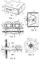
- Figs. 1-5 there is shown the mattress handle of the present invention which is generally designated by the numeral 2, and is shown in use on a bed spring or mattress 4 of the inner spring type, of usual construction, having coil springs 6 arranged in spaced relation between upper, lower and side fabric pads 8, 10 and 12, respectively, which define a mattress cover.
- the side portion 12 of the mattress cover has therein a plurality of handle receiving grommets 16 or the like of any suitable construction which provide openings 18 therein for receiving a handle intended for use in lifting the mattress.
- the mattress handle 2 includes a strap-like hand grippable member 14 constructed to extend along the outer surface of the side cover portion 12, and having a pair of opposed end portions 20 and 22 each of which extend adjacent a grommet 16.
- Elongate connecting members 24 and 26 are secured to the grippable member end portions 20 and 22, respectively, and are constructed to fit through the grommets 16.
- the connecting members 24, 26 each include a connecting end portion 28 which when inserted through the grommet 16, extends to a position adjacent the inner coil spring assembly 6 of the mattress 4.
- the connecting end portion 28 includes a slot 30 therein and an opening 32 which leads into the slot 30.
- the slot 30 is partitioned into a receiving portion 34 and a locking portion 36 by a flexible and resilient finger member 38 which extends substantially transversely across the slot 30.
- the slot 30, opening 32 and finger member 38 are constructed to enable a transverse rod-like member 40 within the mattress spring assembly to be inserted through the opening 32 into the receiving portion 34, and past the finger member 38 into the locking portion 36.
- the finger member 38 operates to prevent the rod-like member from returning back to the receiving portion 34 of the slot 30 once it is moved into the locking portion 36 past the finger member 38.
- the opening 32 is positioned adjacent one end of the slot 30, and the finger member 38 is secured to a sidewall of the slot 30 and extends therefrom angularly away from the opening 32 to a position adjacent an opposing side wall of the slot, thereby enabling the rod-like member to enter but not exit the locking portion 36 of the slot 30.
- the rod-like member 40 extends through intermediate turns of adjacent springs 6 and substantially transverse to the connecting members 24 and 26, and is received in the locking portions 36 thereof, thereby securely connecting the handle 2 to the inner spring assembly.
- the connecting members 24 and 26 may be connected to any other suitable elongate member within the spring assembly, such as the spring itself, a border wire or the like.
- the rod-like member includes inwardly extending end portions 42 which are bent for engagement with the connecting members 24 and 26 to prevent longitudinal movement of the rod-like member 40 out of the slot 30.
- the rod-like member may be inserted at any suitable location in the inner spring assembly so that the connecting members are positioned to effectively connect the handle 2 to the spring assembly 6, and so that the strain applied to the mattress 4 by lifting the same by the handle 2 will be transmitted mostly to the inner spring assembly 6, thereby preventing tearing of the mattress cover side portion 12 or pulling out of the grommets 16.
- the end portions 20 and 22 of the hand grippable member 14 each include a head portion 44 which is constructed to fit against the outer surface of the grommet 16.
- the connecting members 24 and 26 preferably include resilient retaining means 46 extending laterally therefrom and shaped to enable the retaining means 46 to yieldingly contract to allow the connecting members 24 and 26 to pass through the grommet 16, and to expand once therethrough to a position in which the retaining means 46 contact an internal surface of the grommet 16, thereby retaining the grommet 16 between the head portion 44 and the retaining means 46.
- the retaining means 46 includes a plurality of spaced, radially extending, flexible and resilient retaining finger members 48.
- the handle 2 including all of the parts hereinbefore described, is integrally formed of a synthetic plastic material, but any other suitable material may be used.
- the present invention as hereinbefore described provides a simple, inexpensive and reliable handle for a mattress which can easily be used with a conventional mattress to enable it to be lifted, moved and/or turned without damaging the fabric cover.
Landscapes
- Mattresses And Other Support Structures For Chairs And Beds (AREA)
- Clamps And Clips (AREA)
- Emergency Lowering Means (AREA)
- Component Parts Of Construction Machinery (AREA)
Claims (7)
- Vorrichtung mit Griff, kombiniert mit einer Matratze mit Rahmen, der innen mit Spiralfedern (6) und Stangenelementen (40) versehen ist, die sich durch die in einer Stoffhülle (8,10,12) eingeschlossenen Spiralfedern erstrecken, wobei der Griff mit Dichtungen (16) versehen ist, die in der Stoffhülle positioniert sind; die genannte Vorrichtung mit Griff umfaßt ein mit der Hand ergreifbares Riemenelement (14), das an einer Außenfläche der genannten Hülle entlangläuft, wobei das genannte ergreifbare Element ein Paar Endteile (20,22) umfaßt, die jeweils neben einem Paar Dichtungen (16) positioniert sind; an jedem Endteil (20,22) ist ein verlängertes, nach innen reichendes Verbindungsstück (24,26) befestigt, das durch eine Dichtung führt; jedes dieser Verbindungsstücke (24,26) hat einen inneren Verbindungsendteil (28), der neben den Spiralfedern liegt, wobei der genannte Verbindungsendteil (28) einen im wesentlichen in Längsrichtung verlaufenden Schlitz (30) und eine Öffnung (32) aufweist, die in den genannten Schlitz führt und außerhalb desselben liegt,
dadurch gekennzeichnet, daß der genannte Schlitz (30) durch ein biegsames und elastisches Fingerelement (38), das sich im wesentlichen quer durch den Schlitz erstreckt, in einen Aufnahmeteil (34) und einen Schließteil (36) gegliedert ist, wodurch ein Stangenelement (40) durch die genannte Öffnung (32) in den Aufnahmeteil des Schlitzes (34) und hinter das genannte Fingerelement (38) in das Innere des genannten Schließteils des Schlitzes (36) geschoben werden kann, wobei das genannte Fingerelement (38) in der Lage ist, zu verhindern, daß das Stangenelement (40) sich, sobald es sich im Schließteil (36) befindet, hinter den genannten Aufnahmeteil des Schlitzes (34) verschieben kann, wodurch das genannte Verbindungelement (24,26) auf sichere Weise mit dem Stangenelement (40) verbunden wird. - Vorrichtung wie in Anspruch 1 beschrieben, bei der die genannten Endteile (20,22) des genannten ergreifbaren Elements (14) jeweils einen Kopfteil (44) umfassen, der in der Lage ist, sich gegen eine Außenfläche der Dichtung (16) zu legen, und bei der die genannten Verbindungselemente ferner jeweils elastische Haltevorrichtungen (46) umfassen, die sich seitlich des Verbindungselementes nach außen erstrecken und entsprechend geformt sind, um es den genannten Haltevorrichtungen (46) zu ermöglichen, sich nachgiebig zusammenzuziehen, um durch die Dichtung durchzugehen und sich in einer Position auszudehnen, in der die Haltevorrichtungen mit einer Innenfläche der Dichtung in Berührung treten, sobald die genannten Verbindungselemente in die Vorrichtung geschoben werden, zur Befestigung und den Sitz der Dichtung zwischen dem genannten Kopfteil und den genannten Haltevorrichtungen.
- Vorrichtung wie in Anspruch 2 beschrieben, bei der die genannte Haltevorrichtung (46) mehrere, auseinander liegende, biegsame und elastische Fingerelemente (48) umfaßt, die strahlenförmig angebracht sind.
- Vorrichtung wie in Anspruch 1 beschrieben, bei der die genannte Öffnung (32) neben dem inneren Ende des genannten Schlitzes (30) positioniert ist und das genannte Fingerelement (48) an einer Seitenwand des genannten Schlitzes befestigt ist und sich von dieser in einem Winkel von der genannten Öffnung weg zu einer Position neben einer entgegengesetzten Seitenwand des genannten Schlitzes erstreckt und dadurch ermöglicht, daß das Stangenelement (40) in den Schließteil des Schlitzes eintritt, aber nicht aus diesem austreten kann.
- Vorrichtung wie in Anspruch 1 beschrieben, bei der ein Stangenelement (40) sich durch Zwischenwindungen der genannten Spiralfedern (6) erstreckt, die neben und im wesentlichen quer zu den genannten Verbindungselementen (24,26) liegen und bei dem das genannte Stangenelement ferner durch die genannten Schließteile (36) der genannten Schlitze (30) geht und dadurch die genannten Verbindungslemente auf sichere Weise mit den genannten Spiralfedern verbindet.
- Vorrichtung wie in Anspruch 5 beschrieben, bei der das genannte Stangenelement (40) gebogene Endteile (42) aufweist, um sich mit den genannten Elementen (24,26) zu verbinden, wodurch die Längsbewegung des genannten Stangenelements aus den genannten Schlitzen (30) heraus verhindert wird.
- Vorrichtung wie in Anspruch 2 beschrieben, bei der das genannte ergreifbare Element (14) und die genannten Verbindungselemente (24,26) vollkommen aus Kunststoff geformt sind.
Applications Claiming Priority (3)
| Application Number | Priority Date | Filing Date | Title |
|---|---|---|---|
| US07/960,641 US5214810A (en) | 1992-10-14 | 1992-10-14 | Mattress handle construction |
| US960641 | 1992-10-14 | ||
| PCT/US1993/007325 WO1994008495A1 (en) | 1992-10-14 | 1993-08-05 | Mattress handle construction |
Publications (3)
| Publication Number | Publication Date |
|---|---|
| EP0664681A1 EP0664681A1 (de) | 1995-08-02 |
| EP0664681A4 EP0664681A4 (de) | 1996-05-15 |
| EP0664681B1 true EP0664681B1 (de) | 1998-07-22 |
Family
ID=25503429
Family Applications (1)
| Application Number | Title | Priority Date | Filing Date |
|---|---|---|---|
| EP93918634A Expired - Lifetime EP0664681B1 (de) | 1992-10-14 | 1993-08-05 | Matratzenhandgriff |
Country Status (11)
| Country | Link |
|---|---|
| US (1) | US5214810A (de) |
| EP (1) | EP0664681B1 (de) |
| KR (1) | KR100229702B1 (de) |
| CN (1) | CN1079222C (de) |
| AT (1) | ATE168539T1 (de) |
| AU (1) | AU668757B2 (de) |
| CA (1) | CA2146262C (de) |
| DE (1) | DE69319918D1 (de) |
| MY (1) | MY110070A (de) |
| WO (1) | WO1994008495A1 (de) |
| ZA (1) | ZA937564B (de) |
Families Citing this family (8)
| Publication number | Priority date | Publication date | Assignee | Title |
|---|---|---|---|---|
| US5652984A (en) * | 1995-07-19 | 1997-08-05 | Korb; Lothar | Mattress handle |
| DE19710322A1 (de) * | 1997-03-13 | 1998-09-17 | Mecano Rapid Gmbh | Bauteil zur Befestigung eines Bezuges auf der Polsterung eines Sitzes |
| US6000075A (en) * | 1998-04-22 | 1999-12-14 | Sunrise Medical Ccg Inc. | Handle engagable with a grid structure |
| US5924150A (en) * | 1998-06-05 | 1999-07-20 | L&P Property Management Company | Mattress edge support spring and handle structure |
| DE20015450U1 (de) * | 2000-09-06 | 2000-11-23 | Bettina Matratzenfabrik GmbH, 50189 Elsdorf | Matratzen mit umlaufenden Wendegriffen |
| US20030175473A1 (en) * | 2002-03-14 | 2003-09-18 | Timothy Gillum | Surgical table pad with fluid waste channel |
| US20060080782A1 (en) * | 2004-10-14 | 2006-04-20 | Dreamwell, Ltd. | Systems and methods for forming handles in furniture |
| US20080104753A1 (en) * | 2006-11-08 | 2008-05-08 | Kajdas Barbara K | Mattress carrying case |
Family Cites Families (8)
| Publication number | Priority date | Publication date | Assignee | Title |
|---|---|---|---|---|
| US2021238A (en) * | 1934-08-06 | 1935-11-19 | Charles D Karr | Mattress and handle therefor |
| US2194407A (en) * | 1937-12-29 | 1940-03-19 | Rolstone Alfred Sydney George | Handle for mattresses |
| US2224301A (en) * | 1939-02-02 | 1940-12-10 | Palmer Brothers Company | Mattress |
| US2322995A (en) * | 1942-03-16 | 1943-06-29 | James E Allen | Mattress handle |
| US3351964A (en) * | 1966-06-21 | 1967-11-14 | Michael D Anson | Inner spring mattress and handle combination |
| US3590405A (en) * | 1969-03-27 | 1971-07-06 | Ther A Pedic Ass Inc | Handle structure for bed springs and the like |
| US3995337A (en) * | 1975-06-11 | 1976-12-07 | Ther-A-Pedic Associates, Inc. | Mattress construction |
| JPH035359Y2 (de) * | 1985-09-30 | 1991-02-12 |
-
1992
- 1992-10-14 US US07/960,641 patent/US5214810A/en not_active Expired - Fee Related
-
1993
- 1993-08-05 EP EP93918634A patent/EP0664681B1/de not_active Expired - Lifetime
- 1993-08-05 DE DE69319918T patent/DE69319918D1/de not_active Expired - Lifetime
- 1993-08-05 AU AU48021/93A patent/AU668757B2/en not_active Ceased
- 1993-08-05 KR KR1019950701440A patent/KR100229702B1/ko not_active Expired - Fee Related
- 1993-08-05 WO PCT/US1993/007325 patent/WO1994008495A1/en not_active Ceased
- 1993-08-05 AT AT93918634T patent/ATE168539T1/de not_active IP Right Cessation
- 1993-08-05 CA CA002146262A patent/CA2146262C/en not_active Expired - Fee Related
- 1993-10-01 MY MYPI93002004A patent/MY110070A/en unknown
- 1993-10-12 ZA ZA937564A patent/ZA937564B/xx unknown
- 1993-10-14 CN CN93120522A patent/CN1079222C/zh not_active Expired - Fee Related
Also Published As
| Publication number | Publication date |
|---|---|
| CA2146262C (en) | 1997-10-28 |
| ATE168539T1 (de) | 1998-08-15 |
| US5214810A (en) | 1993-06-01 |
| KR100229702B1 (ko) | 1999-11-15 |
| EP0664681A1 (de) | 1995-08-02 |
| CN1079222C (zh) | 2002-02-20 |
| EP0664681A4 (de) | 1996-05-15 |
| WO1994008495A1 (en) | 1994-04-28 |
| AU4802193A (en) | 1994-05-09 |
| CN1111496A (zh) | 1995-11-15 |
| ZA937564B (en) | 1994-06-01 |
| MY110070A (en) | 1997-12-31 |
| KR950703298A (ko) | 1995-09-20 |
| DE69319918D1 (de) | 1998-08-27 |
| AU668757B2 (en) | 1996-05-16 |
Similar Documents
| Publication | Publication Date | Title |
|---|---|---|
| EP0664681B1 (de) | Matratzenhandgriff | |
| US3590405A (en) | Handle structure for bed springs and the like | |
| JPH02127241U (de) | ||
| USRE24386E (en) | Bechik | |
| KR200277447Y1 (ko) | 고정밴드 | |
| US5611126A (en) | Casket and fabric retainer members therefor | |
| JPS606255Y2 (ja) | ヘア−ブラシ | |
| JP4889145B2 (ja) | ペットの引紐 | |
| JPH0340706Y2 (de) | ||
| JP3000065U (ja) | 容器における紐の取付構造 | |
| JPH03129235U (de) | ||
| JPH0214637Y2 (de) | ||
| JPH0523866U (ja) | 釣糸ガイド | |
| KR0137507Y1 (ko) | 차량용 콘솔박스 개폐용 래치구조 | |
| JPS6039Y2 (ja) | ハンデイモツプ | |
| JPH035650Y2 (de) | ||
| JPS5916287Y2 (ja) | 締結具 | |
| JPH0469880U (de) | ||
| JPS6327660Y2 (de) | ||
| US2729867A (en) | Buckle frame and covering therefor | |
| JPH0335846U (de) | ||
| KR900007773Y1 (ko) | 차량용 무선기기 착탈 장치 | |
| JPS6344398Y2 (de) | ||
| KR890004546Y1 (ko) | 쌀통 | |
| JPH01116520U (de) |
Legal Events
| Date | Code | Title | Description |
|---|---|---|---|
| PUAI | Public reference made under article 153(3) epc to a published international application that has entered the european phase |
Free format text: ORIGINAL CODE: 0009012 |
|
| 17P | Request for examination filed |
Effective date: 19950424 |
|
| AK | Designated contracting states |
Kind code of ref document: A1 Designated state(s): AT BE CH DE DK ES FR GB GR IE IT LI LU MC NL PT SE |
|
| A4 | Supplementary search report drawn up and despatched |
Effective date: 19960327 |
|
| AK | Designated contracting states |
Kind code of ref document: A4 Designated state(s): AT BE CH DE DK ES FR GB GR IE IT LI LU MC NL PT SE |
|
| 17Q | First examination report despatched |
Effective date: 19970401 |
|
| GRAG | Despatch of communication of intention to grant |
Free format text: ORIGINAL CODE: EPIDOS AGRA |
|
| GRAG | Despatch of communication of intention to grant |
Free format text: ORIGINAL CODE: EPIDOS AGRA |
|
| GRAH | Despatch of communication of intention to grant a patent |
Free format text: ORIGINAL CODE: EPIDOS IGRA |
|
| GRAH | Despatch of communication of intention to grant a patent |
Free format text: ORIGINAL CODE: EPIDOS IGRA |
|
| GRAA | (expected) grant |
Free format text: ORIGINAL CODE: 0009210 |
|
| AK | Designated contracting states |
Kind code of ref document: B1 Designated state(s): AT BE CH DE DK ES FR GB GR IE IT LI LU MC NL PT SE |
|
| PG25 | Lapsed in a contracting state [announced via postgrant information from national office to epo] |
Ref country code: NL Free format text: LAPSE BECAUSE OF FAILURE TO SUBMIT A TRANSLATION OF THE DESCRIPTION OR TO PAY THE FEE WITHIN THE PRESCRIBED TIME-LIMIT Effective date: 19980722 Ref country code: LI Free format text: LAPSE BECAUSE OF FAILURE TO SUBMIT A TRANSLATION OF THE DESCRIPTION OR TO PAY THE FEE WITHIN THE PRESCRIBED TIME-LIMIT Effective date: 19980722 Ref country code: GR Free format text: LAPSE BECAUSE OF FAILURE TO SUBMIT A TRANSLATION OF THE DESCRIPTION OR TO PAY THE FEE WITHIN THE PRESCRIBED TIME-LIMIT Effective date: 19980722 Ref country code: FR Free format text: LAPSE BECAUSE OF FAILURE TO SUBMIT A TRANSLATION OF THE DESCRIPTION OR TO PAY THE FEE WITHIN THE PRESCRIBED TIME-LIMIT Effective date: 19980722 Ref country code: ES Free format text: THE PATENT HAS BEEN ANNULLED BY A DECISION OF A NATIONAL AUTHORITY Effective date: 19980722 Ref country code: CH Free format text: LAPSE BECAUSE OF FAILURE TO SUBMIT A TRANSLATION OF THE DESCRIPTION OR TO PAY THE FEE WITHIN THE PRESCRIBED TIME-LIMIT Effective date: 19980722 Ref country code: BE Free format text: LAPSE BECAUSE OF FAILURE TO SUBMIT A TRANSLATION OF THE DESCRIPTION OR TO PAY THE FEE WITHIN THE PRESCRIBED TIME-LIMIT Effective date: 19980722 Ref country code: AT Free format text: LAPSE BECAUSE OF FAILURE TO SUBMIT A TRANSLATION OF THE DESCRIPTION OR TO PAY THE FEE WITHIN THE PRESCRIBED TIME-LIMIT Effective date: 19980722 |
|
| REF | Corresponds to: |
Ref document number: 168539 Country of ref document: AT Date of ref document: 19980815 Kind code of ref document: T |
|
| REG | Reference to a national code |
Ref country code: CH Ref legal event code: EP |
|
| PG25 | Lapsed in a contracting state [announced via postgrant information from national office to epo] |
Ref country code: LU Free format text: LAPSE BECAUSE OF NON-PAYMENT OF DUE FEES Effective date: 19980805 |
|
| REF | Corresponds to: |
Ref document number: 69319918 Country of ref document: DE Date of ref document: 19980827 |
|
| PG25 | Lapsed in a contracting state [announced via postgrant information from national office to epo] |
Ref country code: SE Free format text: LAPSE BECAUSE OF FAILURE TO SUBMIT A TRANSLATION OF THE DESCRIPTION OR TO PAY THE FEE WITHIN THE PRESCRIBED TIME-LIMIT Effective date: 19981022 Ref country code: PT Free format text: LAPSE BECAUSE OF FAILURE TO SUBMIT A TRANSLATION OF THE DESCRIPTION OR TO PAY THE FEE WITHIN THE PRESCRIBED TIME-LIMIT Effective date: 19981022 Ref country code: DK Free format text: LAPSE BECAUSE OF FAILURE TO SUBMIT A TRANSLATION OF THE DESCRIPTION OR TO PAY THE FEE WITHIN THE PRESCRIBED TIME-LIMIT Effective date: 19981022 |
|
| PG25 | Lapsed in a contracting state [announced via postgrant information from national office to epo] |
Ref country code: DE Free format text: LAPSE BECAUSE OF FAILURE TO SUBMIT A TRANSLATION OF THE DESCRIPTION OR TO PAY THE FEE WITHIN THE PRESCRIBED TIME-LIMIT Effective date: 19981023 |
|
| RAP4 | Party data changed (patent owner data changed or rights of a patent transferred) |
Owner name: THER-A-PEDIC ASSOCIATES, INC. |
|
| REG | Reference to a national code |
Ref country code: IE Ref legal event code: FG4D |
|
| EN | Fr: translation not filed | ||
| NLV1 | Nl: lapsed or annulled due to failure to fulfill the requirements of art. 29p and 29m of the patents act | ||
| REG | Reference to a national code |
Ref country code: CH Ref legal event code: PL |
|
| PG25 | Lapsed in a contracting state [announced via postgrant information from national office to epo] |
Ref country code: MC Free format text: LAPSE BECAUSE OF NON-PAYMENT OF DUE FEES Effective date: 19990228 |
|
| PLBE | No opposition filed within time limit |
Free format text: ORIGINAL CODE: 0009261 |
|
| STAA | Information on the status of an ep patent application or granted ep patent |
Free format text: STATUS: NO OPPOSITION FILED WITHIN TIME LIMIT |
|
| 26N | No opposition filed | ||
| REG | Reference to a national code |
Ref country code: GB Ref legal event code: IF02 |
|
| PGFP | Annual fee paid to national office [announced via postgrant information from national office to epo] |
Ref country code: GB Payment date: 20040721 Year of fee payment: 12 |
|
| PGFP | Annual fee paid to national office [announced via postgrant information from national office to epo] |
Ref country code: IE Payment date: 20040824 Year of fee payment: 12 |
|
| PG25 | Lapsed in a contracting state [announced via postgrant information from national office to epo] |
Ref country code: IT Free format text: LAPSE BECAUSE OF NON-PAYMENT OF DUE FEES;WARNING: LAPSES OF ITALIAN PATENTS WITH EFFECTIVE DATE BEFORE 2007 MAY HAVE OCCURRED AT ANY TIME BEFORE 2007. THE CORRECT EFFECTIVE DATE MAY BE DIFFERENT FROM THE ONE RECORDED. Effective date: 20050805 Ref country code: IE Free format text: LAPSE BECAUSE OF NON-PAYMENT OF DUE FEES Effective date: 20050805 Ref country code: GB Free format text: LAPSE BECAUSE OF NON-PAYMENT OF DUE FEES Effective date: 20050805 |
|
| GBPC | Gb: european patent ceased through non-payment of renewal fee |
Effective date: 20050805 |
|
| REG | Reference to a national code |
Ref country code: IE Ref legal event code: MM4A |