EP0663565B1 - Roststab und Rost mit Kühleinrichtung und Verfahren zur Kühlung - Google Patents
Roststab und Rost mit Kühleinrichtung und Verfahren zur Kühlung Download PDFInfo
- Publication number
- EP0663565B1 EP0663565B1 EP94116297A EP94116297A EP0663565B1 EP 0663565 B1 EP0663565 B1 EP 0663565B1 EP 94116297 A EP94116297 A EP 94116297A EP 94116297 A EP94116297 A EP 94116297A EP 0663565 B1 EP0663565 B1 EP 0663565B1
- Authority
- EP
- European Patent Office
- Prior art keywords
- grate
- bars
- bar
- grate bars
- grate bar
- Prior art date
- Legal status (The legal status is an assumption and is not a legal conclusion. Google has not performed a legal analysis and makes no representation as to the accuracy of the status listed.)
- Revoked
Links
- 238000001816 cooling Methods 0.000 title claims abstract description 40
- 238000002485 combustion reaction Methods 0.000 claims abstract description 19
- 239000002826 coolant Substances 0.000 claims abstract description 18
- 238000000034 method Methods 0.000 claims abstract description 6
- 239000000498 cooling water Substances 0.000 claims description 6
- 230000000284 resting effect Effects 0.000 claims description 3
- 229910001018 Cast iron Inorganic materials 0.000 claims description 2
- 238000004519 manufacturing process Methods 0.000 claims 1
- XLYOFNOQVPJJNP-UHFFFAOYSA-N water Substances O XLYOFNOQVPJJNP-UHFFFAOYSA-N 0.000 abstract description 19
- 230000015572 biosynthetic process Effects 0.000 abstract description 4
- JEIPFZHSYJVQDO-UHFFFAOYSA-N iron(III) oxide Inorganic materials O=[Fe]O[Fe]=O JEIPFZHSYJVQDO-UHFFFAOYSA-N 0.000 description 7
- 230000000694 effects Effects 0.000 description 4
- 238000010586 diagram Methods 0.000 description 3
- 238000002156 mixing Methods 0.000 description 3
- 238000004056 waste incineration Methods 0.000 description 3
- 238000005260 corrosion Methods 0.000 description 2
- 230000007797 corrosion Effects 0.000 description 2
- 239000010791 domestic waste Substances 0.000 description 2
- 238000010304 firing Methods 0.000 description 2
- 239000007789 gas Substances 0.000 description 2
- 238000010438 heat treatment Methods 0.000 description 2
- 239000000463 material Substances 0.000 description 2
- 239000000126 substance Substances 0.000 description 2
- 239000002699 waste material Substances 0.000 description 2
- 238000005299 abrasion Methods 0.000 description 1
- 230000006978 adaptation Effects 0.000 description 1
- QVGXLLKOCUKJST-UHFFFAOYSA-N atomic oxygen Chemical compound [O] QVGXLLKOCUKJST-UHFFFAOYSA-N 0.000 description 1
- 238000009835 boiling Methods 0.000 description 1
- 238000009833 condensation Methods 0.000 description 1
- 230000005494 condensation Effects 0.000 description 1
- 230000003247 decreasing effect Effects 0.000 description 1
- 238000007872 degassing Methods 0.000 description 1
- 230000001419 dependent effect Effects 0.000 description 1
- 238000011161 development Methods 0.000 description 1
- 230000018109 developmental process Effects 0.000 description 1
- 238000001035 drying Methods 0.000 description 1
- 238000005516 engineering process Methods 0.000 description 1
- 239000004744 fabric Substances 0.000 description 1
- 238000011049 filling Methods 0.000 description 1
- 239000013505 freshwater Substances 0.000 description 1
- 238000002309 gasification Methods 0.000 description 1
- 239000011521 glass Substances 0.000 description 1
- 230000007257 malfunction Effects 0.000 description 1
- 239000001301 oxygen Substances 0.000 description 1
- 229910052760 oxygen Inorganic materials 0.000 description 1
- 239000004033 plastic Substances 0.000 description 1
- 229920003023 plastic Polymers 0.000 description 1
- 238000003825 pressing Methods 0.000 description 1
- 238000004064 recycling Methods 0.000 description 1
- 230000005514 two-phase flow Effects 0.000 description 1
- 238000010792 warming Methods 0.000 description 1
Images


Classifications
-
- F—MECHANICAL ENGINEERING; LIGHTING; HEATING; WEAPONS; BLASTING
- F23—COMBUSTION APPARATUS; COMBUSTION PROCESSES
- F23H—GRATES; CLEANING OR RAKING GRATES
- F23H3/00—Grates with hollow bars
- F23H3/02—Grates with hollow bars internally cooled
-
- F—MECHANICAL ENGINEERING; LIGHTING; HEATING; WEAPONS; BLASTING
- F23—COMBUSTION APPARATUS; COMBUSTION PROCESSES
- F23G—CREMATION FURNACES; CONSUMING WASTE PRODUCTS BY COMBUSTION
- F23G5/00—Incineration of waste; Incinerator constructions; Details, accessories or control therefor
- F23G5/002—Incineration of waste; Incinerator constructions; Details, accessories or control therefor characterised by their grates
-
- F—MECHANICAL ENGINEERING; LIGHTING; HEATING; WEAPONS; BLASTING
- F23—COMBUSTION APPARATUS; COMBUSTION PROCESSES
- F23H—GRATES; CLEANING OR RAKING GRATES
- F23H1/00—Grates with solid bars
- F23H1/02—Grates with solid bars having provision for air supply or air preheating, e.g. air-supply or blast fittings which form a part of the grate structure or serve as supports
-
- F—MECHANICAL ENGINEERING; LIGHTING; HEATING; WEAPONS; BLASTING
- F23—COMBUSTION APPARATUS; COMBUSTION PROCESSES
- F23H—GRATES; CLEANING OR RAKING GRATES
- F23H2700/00—Grates characterised by special features or applications
- F23H2700/009—Grates specially adapted for incinerators
-
- F—MECHANICAL ENGINEERING; LIGHTING; HEATING; WEAPONS; BLASTING
- F23—COMBUSTION APPARATUS; COMBUSTION PROCESSES
- F23H—GRATES; CLEANING OR RAKING GRATES
- F23H2900/00—Special features of combustion grates
- F23H2900/03021—Liquid cooled grates
Definitions
- the invention relates to a grate bar and grate Cooling device and a method for cooling for Incinerators, especially from Waste incineration plants.
- a grate with cooled grate bars is already known from document DE-U-9 309 198.
- a grate for incinerators is usually formed by rows of grate bars that lie one above the other and extend transversely to the transport direction of the firing material. Grate firing is also used as a tried and tested apparatus for domestic waste incineration. The individual grids are covered with grate bars. These have the task of transporting the garbage, mixing (so-called stoking) and taking over the burnout. The processes of drying, preheating, degassing, gasification and C-burnout run on the grate, and thus the grate bars, one after the other.
- the grate bars are provided with openings (slots, Gaps, holes, etc.) through the combustion air is blown.
- the grate bars are particularly stressed by mechanical Abrasion as well as thermal and chemical wear. Corresponding wear leads to changes in the Fire management, the burnout qualities and ultimately too Business interruptions.
- the wear of the grate bars is essentially temperature-dependent.
- the invention has for its object grate bars and to create a grate that burns when burning high-calorie fabrics are wear-resistant, their shape do not change and thus also the combustion behavior as well as the transport and mixing behavior in the oven change.
- good emergency running properties are said to Water loss and a relatively low warming of the Water to less than 100 degrees Celsius is preferred less than 50 degrees Celsius can be reached.
- steam formation is to be effectively prevented will.
- the grate bar according to the invention with a cooling device on which at least one inlet and one outlet opening are arranged has at least one channel for guidance in the grate bar of cooling water, essentially in the longitudinal direction of the Rust bar, on. Since the longitudinal direction of the grate bar This corresponds to the material feed device particularly good cooling of the individual grate bars reached. By cooling every single grate bar the heating of the cooling medium can be relatively low being held. This increases the operational safety of the Cooling and the service life of the grates respectively Cooling system. Water is preferred as the cooling medium used. Other, higher-boiling cooling media are for special applications can also be used.
- the channel arranged in the grate bar preferably has two, substantially parallel sections with each other opposite flow direction, this with one arranged in the head area of the grate bar Redirection are connected.
- the sections of the canal with opposite flow direction can in the horizontal or vertical plane side by side or lie on top of each other.
- the channels are in the With regard to the heat to be dissipated fluidically optimized so that the heating of the coolant is not more than about 50 degrees Celsius, preferably about 20 degrees Celsius is.
- approximately parallel sections of the cooling channel can this different cross-sectional shapes and areas exhibit.
- the one arranged in the head area of the grate bar Redirection can lie in the plane caused by the Central axes of the approximately parallel sections of the Cooling channel goes.
- the deflection is preferred up to the range of an adjacent row of grate bars resting on the edge of the Grate rod head led. It is in the area of The grate bar head is approximately U-shaped.
- the inlet and outlet openings for the coolant are arranged at the foot of the grate bar in the area of the coolant at the foot of the grate bar in the area of the grate bar support.
- Air outlet openings for combustion air are further preferably arranged in the head part. This further improves the cooling of the grate bar.
- recesses for the exit of combustion air are also arranged in the long sides of the grate bar.
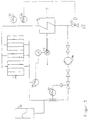
- This Cooling system advantageously consists of one Expansion or compensation vessel (32), the cooled Grate bars (34), a recooler (35) and a pump (36) and a connection (31) for filling or Draining of the cooling system together with the pressure control valve (33).
- the cooling medium When using water, the cooling medium is in one Cooling system under pressure, preferably between 1 and 6 bar operated. This will cause steam to form avoided and e.g. a two-phase flow or formation of "steam pillows" with correspondingly worse Prevents heat transfer.
- a particularly preferred feature of the invention are between the main inlet and outlet and inlet and Drain opening of the first or last grate bar a row of grate bars or a section of one Row of grate bars in which the inlet and outlet openings of the individual grate bars are connected in series, Valves for the supply or discharge of another Cooling medium, especially air, and Interruption of the main inflow or outflow line arranged.
- This has the advantage that in the event of a leak in one or more grate bars in a row of grate bars air cooling is used instead of water cooling and thus the operation until the next planned Downtime can be maintained.
- rows of grate bars with low thermal loads can be with cheaper cooling media, such as. B. air, cooled will.
- the combination of several rows of grate bars in Parallel connection to rust zones with common connection or Drain pipe and valves for supply or discharge another cooling medium, in particular air, and Shut-off to the main inlet or outlet line discloses a particularly economical variant.
- Figure 1 is a grate bar 1 with grate bar support 2 in Area of the grate bar base 3 shown.
- the grate bar head 4 lies with the edge 5 on a grate bar adjacent row of grate bars.
- the grate bar consists of Cast iron. It has a channel 6, which is approximately parallel Has sections (one behind the other in Figure 1). This parallel sections are by a deflection 7th connected with each other.
- Channel 6 is related Provide drain openings 8. This feed and Drain openings are preferably located directly on the foot side End of the channel 6 attached.
- FIG 2 is a section II-II of Figure 1 through the Grate bar head 4 shown.
- the roughly parallel Sections of channel 6, here referred to as 6 'and 6' ' open into a deflection 7, which is in the plane of Section II is approximately U-shaped down to the bottom Edge 5 of the grate bar head 4 is guided.
- air outlet openings 9 are provided in the grate bar head 4 between and next to the legs of the U-shaped Deflection 7 .
- Figure 3 is a section II of Figure 1 for a Execution shown, in which the deflection is not in the area of the edge 5 is drawn.
- the redirection 7 forms here together with the channel sections 6 'and 6' ' in their plane also an approximately U-shaped Cross-section.
- the sections 6 'and 6 '' can also be arranged one above the other.
- FIG. 1 A flow diagram of a grate is shown in FIG.
- main inlet and the main outlet line 11 of a cooling medium in particular water
- 12 and drain opening 13 of the first 14 and last 15 Grate bar of each row of grate bars their addition or Drain openings of the individual grate bars in a row are connected to one another, valves for supply or Removal 17 of a further cooling medium, in particular air, as well as to interrupt the main inlet 18 or Main drain line 19 arranged.
- the feed of the second Cooling medium takes place via the main supply line 20 or Main discharge line 21.
- a preferred direction of waste flow arrow 22 indicates.
- the grate according to the invention and the grate bar have the Advantage that the grate bars without changing the Incinerator can be used. It stays therefore with the previous combustion technology. That too mechanical transport and mixing behavior (forward / return stroke) stay unchanged. This applies to both the weight also the stroke length and so on.
- the rust is also extremely wear-resistant, as the grate bars are made as before Cast. Therefore, the grate bar according to the invention and rust also have excellent emergency running properties Malfunctions, for example in the event of water failure.
- the grate bars preferably have the hitherto known Form on, with the width of the grate bars approximately doubled is, so that in one half, that is, so far usual grate bar width, the cooling water forward to in head is headed and in the second half again is returned.
- the parallel channel sections face a clear height of about 15 to 25 mm and a clear Width of about 40 to 60 mm.
- the flow rate is between 0.5 and 2 m per second.
- the temperature the grate bar is approximately in the middle between head and Foot area around 100 degrees Celsius. This will make one Corrosion caused by condensation avoided. In the area of Headboard will have a temperature of about 150 degrees Celsius adhered to so that with regard to the burnout behavior no disadvantage arises.
- the Grate bars or the grates in a closed, under Pressure water-cooled cooling system integrated and operated.
- the temperature of the water is for example 90 ° C, but increased to 120 ° C and the system pressure is 1 to 6 bar, preferably 5 bar.
- the cooling system pressure is via a compressor, the air in via a bubble from the water side separated outside space of an expansion vessel or Compensation vessel promotes, adjusted.
- the system pressure in the cooling water circuit is via one in the expansion tank integrated automatic expansion set: On Contact manometer starts the compressor of the Expansion machines as soon as a lower limit pressure in the System is achieved. The compressor is switched off as soon as the pressure reaches an upper limit. At Exceeding an adjustable top Limit pressure value, e.g. 6 bar, air is through a valve blown off. The two switching points are adjustable between 1.0 and 6.0 bar.
- FIG. 5 is the diagram of a cooling device shown.
- the pump 36 promotes this Water through one or more grate bars or grate 34 and the cooling device.
- the expansion or Compensation vessel 32 with a Provide level measuring device, with the help of Automatically falls below a lower limit fresh water is fed into the system and at the same time a message is sent to the control room.
- the infeed will reach an upper limit level automatically interrupted by water. By the frequency the message to the control room about the water feed leaks in the system can be recognized, so that appropriate measures can be initiated.
- the grate bar or each row of grate bars can be locked separately.
- are as measuring devices Water mass flow measuring device 37, a Temperature measuring device, 38, 39 and one Cooling system pressure measuring device 40 is provided. Of the Fan 41 cools the recooler 35.
Landscapes
- Engineering & Computer Science (AREA)
- Mechanical Engineering (AREA)
- General Engineering & Computer Science (AREA)
- Chemical & Material Sciences (AREA)
- Combustion & Propulsion (AREA)
- Incineration Of Waste (AREA)
- Processing Of Solid Wastes (AREA)
- Carbon And Carbon Compounds (AREA)
- Preliminary Treatment Of Fibers (AREA)
- Baking, Grill, Roasting (AREA)
Applications Claiming Priority (2)
| Application Number | Priority Date | Filing Date | Title |
|---|---|---|---|
| DE4400992A DE4400992C1 (de) | 1994-01-14 | 1994-01-14 | Roststab und Rost mit Kühleinrichtung |
| DE4400992 | 1994-01-14 |
Publications (3)
| Publication Number | Publication Date |
|---|---|
| EP0663565A2 EP0663565A2 (de) | 1995-07-19 |
| EP0663565A3 EP0663565A3 (de) | 1996-02-14 |
| EP0663565B1 true EP0663565B1 (de) | 1998-12-09 |
Family
ID=6507958
Family Applications (1)
| Application Number | Title | Priority Date | Filing Date |
|---|---|---|---|
| EP94116297A Revoked EP0663565B1 (de) | 1994-01-14 | 1994-10-15 | Roststab und Rost mit Kühleinrichtung und Verfahren zur Kühlung |
Country Status (8)
| Country | Link |
|---|---|
| US (1) | US5636581A (hu) |
| EP (1) | EP0663565B1 (hu) |
| KR (1) | KR100279201B1 (hu) |
| AT (1) | ATE174418T1 (hu) |
| CA (1) | CA2140218A1 (hu) |
| DE (2) | DE4400992C1 (hu) |
| ES (1) | ES2127867T3 (hu) |
| TW (1) | TW270971B (hu) |
Cited By (1)
| Publication number | Priority date | Publication date | Assignee | Title |
|---|---|---|---|---|
| DE102014008858A1 (de) | 2014-06-16 | 2015-12-17 | Joachim Kümmel | Verfahren zur Verbrennung von Abfall und Biomassen auf einem Flossenwand-Stufenrost sowie Vorrichtung zur Durchführung des Verfahrens |
Families Citing this family (22)
| Publication number | Priority date | Publication date | Assignee | Title |
|---|---|---|---|---|
| DK171048B1 (da) * | 1995-01-24 | 1996-04-29 | Voelund Ecology Systems As | Brændselstransporterende forbrændingsrist til forbrændingsanlæg, navnlig affaldsforbrændingsanlæg |
| CH689519A5 (de) * | 1995-05-17 | 1999-05-31 | Von Roll Umwelttechnik Ag | Gekuehlter Rostblock. |
| DE19528310A1 (de) * | 1995-08-02 | 1997-02-06 | Abb Management Ag | Rost für eine Feuerungsanlage |
| DE19622424C2 (de) * | 1996-06-04 | 1998-10-29 | Martin Umwelt & Energietech | Rostelement und Rost mit Flüssigkeitskühlung |
| DE19648128C2 (de) | 1996-11-21 | 2002-11-07 | Alstom | Rost für eine Feuerungsanlage |
| DE19650742C1 (de) * | 1996-12-06 | 1998-02-19 | Metallgesellschaft Ag | Mit Wasser gekühlter Verbrennungsrost |
| EP0919771B1 (de) * | 1997-10-29 | 2000-11-29 | Doikos Investments Ltd | Verfahren zum Verbrennen von Feststoffen auf einem wassergekühlten Schub-Verbrennungsrost, sowie Rostplatte und Rost zur Ausübung des Verfahrens |
| EP0972989A1 (de) | 1998-07-15 | 2000-01-19 | Asea Brown Boveri AG | Verfahren zur Verbrennung von Feststoffen |
| EP0987494A1 (de) | 1998-09-15 | 2000-03-22 | Asea Brown Boveri AG | Verfahren zur Kühlung eines Rostes für einen Feuerungsraum sowie Rost für einen Feuerungsraum |
| DE19860552C2 (de) * | 1998-12-22 | 2001-02-08 | Mannesmann Ag | Kühlbarer Verbrennungsrost |
| DE19860553C2 (de) * | 1998-12-22 | 2001-03-29 | Mannesmann Ag | Flüssigkeitsgekühlter Verbrennungsrost |
| DE19929614C2 (de) * | 1999-06-28 | 2001-04-26 | Martin Umwelt & Energietech | Feuerungsanlage mit flüssigkeitsgekühlten Rostelementen |
| DE19943665B4 (de) * | 1999-09-13 | 2006-04-13 | Martin GmbH für Umwelt- und Energietechnik | Verfahren zur Kühlung eines Rostes für einen Feuerraum mittels Wasser sowie Rost zur Verbrennung von Feststoffen |
| AU2000266797A1 (en) * | 2000-09-04 | 2002-03-22 | Theodor Koch | Grate bar with liquid cooling for incinerators |
| EP1540251A2 (en) * | 2002-06-24 | 2005-06-15 | John N. Basic Sr. | Temperature-controlled incinerator dryer grates |
| DE102004034322B4 (de) * | 2004-07-15 | 2006-09-28 | Lurgi Lentjes Ag | Rostplatte |
| PL1760400T3 (pl) * | 2005-09-06 | 2009-08-31 | Ernst Schenkel | Chłodzony wodą element rusztu |
| US9032948B1 (en) * | 2008-05-29 | 2015-05-19 | Jeffrey M. Petteway | Seasoning grill |
| EP2751488B1 (de) | 2011-09-01 | 2018-04-11 | Ernst Schenkel | Rost zur feststoffverbrennung |
| DE102014004660A1 (de) | 2014-02-10 | 2015-08-13 | Joachim Kümmel | Verfahren zur Verbrennung von Abfall und Biomassen auf einem luftgekühlten Rost sowie Vorrichtung zur Durchführung des Verfahrens |
| DE102014106200A1 (de) | 2014-05-05 | 2015-11-05 | Tiska Gmbh | kühlbarer Roststab für einen Vorschubrost einer Verbrennungsanlage |
| KR102485539B1 (ko) * | 2022-05-17 | 2023-01-06 | 에스엠메탈(주) | 소각로용 화격자 |
Family Cites Families (17)
| Publication number | Priority date | Publication date | Assignee | Title |
|---|---|---|---|---|
| FR739654A (hu) * | 1900-01-01 | |||
| DE312287C (hu) † | ||||
| DE498538C (de) * | 1930-05-23 | L & C Steinmueller | Wassergekuehlter Treppenrost | |
| US890552A (en) * | 1907-03-11 | 1908-06-09 | David H Rice | Furnace-grate. |
| US1775790A (en) † | 1927-05-25 | 1930-09-16 | Tawlks Grate Bar Company | Grate bar |
| DE515691C (de) * | 1928-10-20 | 1931-01-12 | Telefunken Gmbh | Verfahren zur gleichzeitigen Erzeugung von mehreren Traegerfrequenzen |
| US2171848A (en) † | 1937-03-05 | 1939-09-05 | Maurice A Hofft | Water cooled grate bar |
| US2240590A (en) † | 1938-05-02 | 1941-05-06 | George W Wallace | Automatic fluid cooled grate |
| DE808263C (de) * | 1948-10-02 | 1951-07-12 | Steinmueller Gmbh L & C | Selbstfoerdernder, wassergekuehlter Planrost |
| EP0071681A1 (en) * | 1981-08-10 | 1983-02-16 | Calvin H. Hand | Bio-mass burner |
| GB2143932A (en) † | 1983-07-22 | 1985-02-20 | Gordon Michael Priest | Furnace |
| DE3734043A1 (de) * | 1987-10-08 | 1989-04-20 | Kloeckner Humboldt Deutz Ag | Rostkuehler zum kuehlen von heissem schuettgut |
| JPH02106613A (ja) * | 1988-10-13 | 1990-04-18 | Hitachi Zosen Corp | 焼却炉の火格子構造 |
| DE3902159A1 (de) * | 1989-01-25 | 1990-07-26 | Nils Erik Tunstroemer | Vorrichtung zum verbrennen und/oder thermischen zersetzen von brennmaterial, insbesondere festen brennstoffen |
| DE4105330C1 (hu) * | 1991-02-18 | 1992-08-06 | Noell - K + K Abfalltechnik Gmbh, 4040 Neuss, De | |
| EP0682764B1 (en) * | 1993-02-12 | 1999-08-11 | L David Ostlie | Stacked cooling grate and system for providing thermal power for a power plant |
| CH684118A5 (de) * | 1993-04-20 | 1994-07-15 | Doikos Investments Ltd | Verfahren zum Verbrennen von Kehricht auf einem Verbrennungsrost sowie Verbrennungsrost zur Ausübung des Verfahrens und Rostplatte für einen solchen Verbrennungsrost. |
-
1994
- 1994-01-14 DE DE4400992A patent/DE4400992C1/de not_active Revoked
- 1994-10-15 AT AT94116297T patent/ATE174418T1/de not_active IP Right Cessation
- 1994-10-15 EP EP94116297A patent/EP0663565B1/de not_active Revoked
- 1994-10-15 DE DE59407443T patent/DE59407443D1/de not_active Revoked
- 1994-10-15 ES ES94116297T patent/ES2127867T3/es not_active Expired - Lifetime
-
1995
- 1995-01-05 KR KR1019950000069A patent/KR100279201B1/ko not_active IP Right Cessation
- 1995-01-10 US US08/371,096 patent/US5636581A/en not_active Expired - Fee Related
- 1995-01-13 TW TW084100294A patent/TW270971B/zh active
- 1995-01-13 CA CA002140218A patent/CA2140218A1/en not_active Abandoned
Cited By (1)
| Publication number | Priority date | Publication date | Assignee | Title |
|---|---|---|---|---|
| DE102014008858A1 (de) | 2014-06-16 | 2015-12-17 | Joachim Kümmel | Verfahren zur Verbrennung von Abfall und Biomassen auf einem Flossenwand-Stufenrost sowie Vorrichtung zur Durchführung des Verfahrens |
Also Published As
| Publication number | Publication date |
|---|---|
| DE4400992C1 (de) | 1995-05-11 |
| EP0663565A3 (de) | 1996-02-14 |
| KR950033253A (ko) | 1995-12-22 |
| ES2127867T3 (es) | 1999-05-01 |
| KR100279201B1 (ko) | 2001-02-01 |
| DE59407443D1 (de) | 1999-01-21 |
| EP0663565A2 (de) | 1995-07-19 |
| US5636581A (en) | 1997-06-10 |
| CA2140218A1 (en) | 1995-07-15 |
| TW270971B (hu) | 1996-02-21 |
| ATE174418T1 (de) | 1998-12-15 |
Similar Documents
| Publication | Publication Date | Title |
|---|---|---|
| EP0663565B1 (de) | Roststab und Rost mit Kühleinrichtung und Verfahren zur Kühlung | |
| EP0621449B1 (de) | Verfahren zum Verbrennen von Kehricht auf einem Verbrennungsrost sowie Verbrennungsrost zur Ausübung des Verfahrens und Rostplatte zur Herstellung eines solchen Verbrennungsrostes | |
| EP1617143B1 (de) | Rostplatte, zugehöriger Verbrennungsrost und korrespondierende Reststoffverbrennungsanlage | |
| EP0815396B1 (de) | Verbrennungsrost und verfahren zum optimieren des betriebes eines verbrennungsrostes | |
| EP0954722B1 (de) | Mit wasser gekühlter verbrennungsrost | |
| DE19753981C2 (de) | Flüssigkeitsgekühlte Rostplatte | |
| DE8100050U1 (de) | Rekuperativer waermetauscher mit zyklusumschaltung | |
| DE2740537A1 (de) | Brenner fuer regenerativ-winderhitzer | |
| DE9416320U1 (de) | Reststab und Rest mit Kühleinrichtung | |
| EP1612483B1 (de) | Rostplatte, zugehöriger Verbrennungsrost und korrespondierende Reststoffverbrennungsanlage | |
| WO1996033371A1 (de) | Rost mit kühleinrichtung und verfahren zur kühlung | |
| EP2306086B1 (de) | Roststab | |
| DE19632316C1 (de) | Rostplatte | |
| EP1355112A1 (de) | Verfahren zur Kühlung von Roststäben für Verbrennungsroste, Roststab und Verfahren zur Herstellung eines Roststabes | |
| WO2022053550A1 (de) | Wassergekühlter rostblock für eine verbrennungsanlage | |
| EP0008667B1 (de) | Ofen zur Wärmebehandlung von stückigem bis feinkörnigem Gut | |
| DE387705C (de) | Wassergekuehlte Gleitschiene fuer Waermoefen | |
| DE69513039T2 (de) | Verfahren und vorrichtung zum ändern der wärmeübertragungsfläche eines wirbelbettes | |
| DE10223639A1 (de) | Gekühlte Transportrolle für einen Ofen zur Wärmebehandlung von Körpern, insbesondere Brammen | |
| EP0879998A2 (de) | Vorwärmer für Gas | |
| CH610647A5 (en) | Shaft furnace installation for burning lumpy, in particular endothermally reacting material | |
| JP2024029906A (ja) | ストーカ装置の水冷式冷却装置及びストーカ装置の水冷式冷却装置の設計方法 | |
| DE8908459U1 (de) | Vorrichtung zum Erwärmen einer Flüssigkeit, insbesondere Wasserheizer | |
| EP2927593A1 (de) | Silobrennkammer für eine Gasturbine | |
| EP1035373A1 (de) | Rostsystem für einen Brennstoffkessel |
Legal Events
| Date | Code | Title | Description |
|---|---|---|---|
| PUAI | Public reference made under article 153(3) epc to a published international application that has entered the european phase |
Free format text: ORIGINAL CODE: 0009012 |
|
| AK | Designated contracting states |
Kind code of ref document: A2 Designated state(s): AT BE CH DE ES FR GB IE IT LI NL SE |
|
| EL | Fr: translation of claims filed | ||
| PUAL | Search report despatched |
Free format text: ORIGINAL CODE: 0009013 |
|
| AK | Designated contracting states |
Kind code of ref document: A3 Designated state(s): AT BE CH DE ES FR GB IE IT LI NL SE |
|
| 17P | Request for examination filed |
Effective date: 19960311 |
|
| 17Q | First examination report despatched |
Effective date: 19970909 |
|
| GRAG | Despatch of communication of intention to grant |
Free format text: ORIGINAL CODE: EPIDOS AGRA |
|
| GRAG | Despatch of communication of intention to grant |
Free format text: ORIGINAL CODE: EPIDOS AGRA |
|
| GRAH | Despatch of communication of intention to grant a patent |
Free format text: ORIGINAL CODE: EPIDOS IGRA |
|
| GRAH | Despatch of communication of intention to grant a patent |
Free format text: ORIGINAL CODE: EPIDOS IGRA |
|
| RAP1 | Party data changed (applicant data changed or rights of an application transferred) |
Owner name: NOELL-KRC ENERGIE- UND UMWELTTECHNIK GMBH |
|
| GRAA | (expected) grant |
Free format text: ORIGINAL CODE: 0009210 |
|
| AK | Designated contracting states |
Kind code of ref document: B1 Designated state(s): AT BE CH DE ES FR GB IE IT LI NL SE |
|
| REF | Corresponds to: |
Ref document number: 174418 Country of ref document: AT Date of ref document: 19981215 Kind code of ref document: T |
|
| REG | Reference to a national code |
Ref country code: CH Ref legal event code: EP |
|
| REF | Corresponds to: |
Ref document number: 59407443 Country of ref document: DE Date of ref document: 19990121 |
|
| REG | Reference to a national code |
Ref country code: IE Ref legal event code: FG4D Free format text: GERMAN |
|
| ITF | It: translation for a ep patent filed | ||
| GBT | Gb: translation of ep patent filed (gb section 77(6)(a)/1977) |
Effective date: 19990308 |
|
| ET | Fr: translation filed | ||
| REG | Reference to a national code |
Ref country code: ES Ref legal event code: FG2A Ref document number: 2127867 Country of ref document: ES Kind code of ref document: T3 |
|
| PLBI | Opposition filed |
Free format text: ORIGINAL CODE: 0009260 |
|
| PLBQ | Unpublished change to opponent data |
Free format text: ORIGINAL CODE: EPIDOS OPPO |
|
| PLBI | Opposition filed |
Free format text: ORIGINAL CODE: 0009260 |
|
| PLBF | Reply of patent proprietor to notice(s) of opposition |
Free format text: ORIGINAL CODE: EPIDOS OBSO |
|
| 26 | Opposition filed |
Opponent name: ALSTHOM ENERGY SYSTEMS Effective date: 19990830 |
|
| 26 | Opposition filed |
Opponent name: ABB KRAFTWERKE AG INTELLECTUAL PROPERTY KWCP C/O A Effective date: 19990908 Opponent name: ALSTHOM ENERGY SYSTEMS Effective date: 19990830 |
|
| NLR1 | Nl: opposition has been filed with the epo |
Opponent name: ABB KRAFTWERKE AG INTELLECTUAL PROPERTY KWCP C/O A Opponent name: ALSTHOM ENERGY SYSTEMS |
|
| PLBF | Reply of patent proprietor to notice(s) of opposition |
Free format text: ORIGINAL CODE: EPIDOS OBSO |
|
| PLBQ | Unpublished change to opponent data |
Free format text: ORIGINAL CODE: EPIDOS OPPO |
|
| PLAB | Opposition data, opponent's data or that of the opponent's representative modified |
Free format text: ORIGINAL CODE: 0009299OPPO |
|
| PLBI | Opposition filed |
Free format text: ORIGINAL CODE: 0009260 |
|
| PLBQ | Unpublished change to opponent data |
Free format text: ORIGINAL CODE: EPIDOS OPPO |
|
| PLAB | Opposition data, opponent's data or that of the opponent's representative modified |
Free format text: ORIGINAL CODE: 0009299OPPO |
|
| PGFP | Annual fee paid to national office [announced via postgrant information from national office to epo] |
Ref country code: FR Payment date: 20000911 Year of fee payment: 7 Ref country code: AT Payment date: 20000911 Year of fee payment: 7 |
|
| PGFP | Annual fee paid to national office [announced via postgrant information from national office to epo] |
Ref country code: IE Payment date: 20000915 Year of fee payment: 7 |
|
| PGFP | Annual fee paid to national office [announced via postgrant information from national office to epo] |
Ref country code: GB Payment date: 20000919 Year of fee payment: 7 |
|
| PGFP | Annual fee paid to national office [announced via postgrant information from national office to epo] |
Ref country code: SE Payment date: 20000920 Year of fee payment: 7 |
|
| PGFP | Annual fee paid to national office [announced via postgrant information from national office to epo] |
Ref country code: CH Payment date: 20000921 Year of fee payment: 7 |
|
| PGFP | Annual fee paid to national office [announced via postgrant information from national office to epo] |
Ref country code: NL Payment date: 20000925 Year of fee payment: 7 |
|
| 26 | Opposition filed |
Opponent name: ABB ALSTOM POWER (SCHWEIZ) AG INTELLECTUAL PROPERT Effective date: 19990908 Opponent name: ABB ALSTOM POWER COMBUSTION GMBH Effective date: 19990830 |
|
| PGFP | Annual fee paid to national office [announced via postgrant information from national office to epo] |
Ref country code: ES Payment date: 20001010 Year of fee payment: 7 |
|
| PGFP | Annual fee paid to national office [announced via postgrant information from national office to epo] |
Ref country code: DE Payment date: 20001016 Year of fee payment: 7 Ref country code: BE Payment date: 20001016 Year of fee payment: 7 |
|
| R26 | Opposition filed (corrected) |
Opponent name: ABB ALSTOM POWER COMBUSTION GMBH * 19990908 ALSTOM Effective date: 19990830 |
|
| PLAW | Interlocutory decision in opposition |
Free format text: ORIGINAL CODE: EPIDOS IDOP |
|
| NLR1 | Nl: opposition has been filed with the epo |
Opponent name: ALSTOM POWER (SCHWEIZ) AG INTELLECTUAL PROPERTY CH Opponent name: ABB ALSTOM POWER (SCHWEIZ) AG INTELLECTUAL PROPERT Opponent name: ABB ALSTOM POWER COMBUSTION GMBH |
|
| PLAW | Interlocutory decision in opposition |
Free format text: ORIGINAL CODE: EPIDOS IDOP |
|
| RDAH | Patent revoked |
Free format text: ORIGINAL CODE: EPIDOS REVO |
|
| RDAG | Patent revoked |
Free format text: ORIGINAL CODE: 0009271 |
|
| STAA | Information on the status of an ep patent application or granted ep patent |
Free format text: STATUS: PATENT REVOKED |
|
| 27W | Patent revoked |
Effective date: 20010907 |
|
| GBPR | Gb: patent revoked under art. 102 of the ep convention designating the uk as contracting state |
Free format text: 20010907 |
|
| REG | Reference to a national code |
Ref country code: CH Ref legal event code: PL |
|
| NLR2 | Nl: decision of opposition | ||
| REG | Reference to a national code |
Ref country code: IE Ref legal event code: MM4A |