EP0663565B1 - Grate bar and grate with cooling device and cooling method - Google Patents
Grate bar and grate with cooling device and cooling method Download PDFInfo
- Publication number
- EP0663565B1 EP0663565B1 EP94116297A EP94116297A EP0663565B1 EP 0663565 B1 EP0663565 B1 EP 0663565B1 EP 94116297 A EP94116297 A EP 94116297A EP 94116297 A EP94116297 A EP 94116297A EP 0663565 B1 EP0663565 B1 EP 0663565B1
- Authority
- EP
- European Patent Office
- Prior art keywords
- grate
- bars
- bar
- grate bars
- grate bar
- Prior art date
- Legal status (The legal status is an assumption and is not a legal conclusion. Google has not performed a legal analysis and makes no representation as to the accuracy of the status listed.)
- Revoked
Links
Images


Classifications
-
- F—MECHANICAL ENGINEERING; LIGHTING; HEATING; WEAPONS; BLASTING
- F23—COMBUSTION APPARATUS; COMBUSTION PROCESSES
- F23H—GRATES; CLEANING OR RAKING GRATES
- F23H3/00—Grates with hollow bars
- F23H3/02—Grates with hollow bars internally cooled
-
- F—MECHANICAL ENGINEERING; LIGHTING; HEATING; WEAPONS; BLASTING
- F23—COMBUSTION APPARATUS; COMBUSTION PROCESSES
- F23G—CREMATION FURNACES; CONSUMING WASTE PRODUCTS BY COMBUSTION
- F23G5/00—Incineration of waste; Incinerator constructions; Details, accessories or control therefor
- F23G5/002—Incineration of waste; Incinerator constructions; Details, accessories or control therefor characterised by their grates
-
- F—MECHANICAL ENGINEERING; LIGHTING; HEATING; WEAPONS; BLASTING
- F23—COMBUSTION APPARATUS; COMBUSTION PROCESSES
- F23H—GRATES; CLEANING OR RAKING GRATES
- F23H1/00—Grates with solid bars
- F23H1/02—Grates with solid bars having provision for air supply or air preheating, e.g. air-supply or blast fittings which form a part of the grate structure or serve as supports
-
- F—MECHANICAL ENGINEERING; LIGHTING; HEATING; WEAPONS; BLASTING
- F23—COMBUSTION APPARATUS; COMBUSTION PROCESSES
- F23H—GRATES; CLEANING OR RAKING GRATES
- F23H2700/00—Grates characterised by special features or applications
- F23H2700/009—Grates specially adapted for incinerators
-
- F—MECHANICAL ENGINEERING; LIGHTING; HEATING; WEAPONS; BLASTING
- F23—COMBUSTION APPARATUS; COMBUSTION PROCESSES
- F23H—GRATES; CLEANING OR RAKING GRATES
- F23H2900/00—Special features of combustion grates
- F23H2900/03021—Liquid cooled grates
Definitions
- the invention relates to a grate bar and grate Cooling device and a method for cooling for Incinerators, especially from Waste incineration plants.
- a grate with cooled grate bars is already known from document DE-U-9 309 198.
- a grate for incinerators is usually formed by rows of grate bars that lie one above the other and extend transversely to the transport direction of the firing material. Grate firing is also used as a tried and tested apparatus for domestic waste incineration. The individual grids are covered with grate bars. These have the task of transporting the garbage, mixing (so-called stoking) and taking over the burnout. The processes of drying, preheating, degassing, gasification and C-burnout run on the grate, and thus the grate bars, one after the other.
- the grate bars are provided with openings (slots, Gaps, holes, etc.) through the combustion air is blown.
- the grate bars are particularly stressed by mechanical Abrasion as well as thermal and chemical wear. Corresponding wear leads to changes in the Fire management, the burnout qualities and ultimately too Business interruptions.
- the wear of the grate bars is essentially temperature-dependent.
- the invention has for its object grate bars and to create a grate that burns when burning high-calorie fabrics are wear-resistant, their shape do not change and thus also the combustion behavior as well as the transport and mixing behavior in the oven change.
- good emergency running properties are said to Water loss and a relatively low warming of the Water to less than 100 degrees Celsius is preferred less than 50 degrees Celsius can be reached.
- steam formation is to be effectively prevented will.
- the grate bar according to the invention with a cooling device on which at least one inlet and one outlet opening are arranged has at least one channel for guidance in the grate bar of cooling water, essentially in the longitudinal direction of the Rust bar, on. Since the longitudinal direction of the grate bar This corresponds to the material feed device particularly good cooling of the individual grate bars reached. By cooling every single grate bar the heating of the cooling medium can be relatively low being held. This increases the operational safety of the Cooling and the service life of the grates respectively Cooling system. Water is preferred as the cooling medium used. Other, higher-boiling cooling media are for special applications can also be used.
- the channel arranged in the grate bar preferably has two, substantially parallel sections with each other opposite flow direction, this with one arranged in the head area of the grate bar Redirection are connected.
- the sections of the canal with opposite flow direction can in the horizontal or vertical plane side by side or lie on top of each other.
- the channels are in the With regard to the heat to be dissipated fluidically optimized so that the heating of the coolant is not more than about 50 degrees Celsius, preferably about 20 degrees Celsius is.
- approximately parallel sections of the cooling channel can this different cross-sectional shapes and areas exhibit.
- the one arranged in the head area of the grate bar Redirection can lie in the plane caused by the Central axes of the approximately parallel sections of the Cooling channel goes.
- the deflection is preferred up to the range of an adjacent row of grate bars resting on the edge of the Grate rod head led. It is in the area of The grate bar head is approximately U-shaped.
- the inlet and outlet openings for the coolant are arranged at the foot of the grate bar in the area of the coolant at the foot of the grate bar in the area of the grate bar support.
- Air outlet openings for combustion air are further preferably arranged in the head part. This further improves the cooling of the grate bar.
- recesses for the exit of combustion air are also arranged in the long sides of the grate bar.
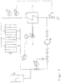
- This Cooling system advantageously consists of one Expansion or compensation vessel (32), the cooled Grate bars (34), a recooler (35) and a pump (36) and a connection (31) for filling or Draining of the cooling system together with the pressure control valve (33).
- the cooling medium When using water, the cooling medium is in one Cooling system under pressure, preferably between 1 and 6 bar operated. This will cause steam to form avoided and e.g. a two-phase flow or formation of "steam pillows" with correspondingly worse Prevents heat transfer.
- a particularly preferred feature of the invention are between the main inlet and outlet and inlet and Drain opening of the first or last grate bar a row of grate bars or a section of one Row of grate bars in which the inlet and outlet openings of the individual grate bars are connected in series, Valves for the supply or discharge of another Cooling medium, especially air, and Interruption of the main inflow or outflow line arranged.
- This has the advantage that in the event of a leak in one or more grate bars in a row of grate bars air cooling is used instead of water cooling and thus the operation until the next planned Downtime can be maintained.
- rows of grate bars with low thermal loads can be with cheaper cooling media, such as. B. air, cooled will.
- the combination of several rows of grate bars in Parallel connection to rust zones with common connection or Drain pipe and valves for supply or discharge another cooling medium, in particular air, and Shut-off to the main inlet or outlet line discloses a particularly economical variant.
- Figure 1 is a grate bar 1 with grate bar support 2 in Area of the grate bar base 3 shown.
- the grate bar head 4 lies with the edge 5 on a grate bar adjacent row of grate bars.
- the grate bar consists of Cast iron. It has a channel 6, which is approximately parallel Has sections (one behind the other in Figure 1). This parallel sections are by a deflection 7th connected with each other.
- Channel 6 is related Provide drain openings 8. This feed and Drain openings are preferably located directly on the foot side End of the channel 6 attached.
- FIG 2 is a section II-II of Figure 1 through the Grate bar head 4 shown.
- the roughly parallel Sections of channel 6, here referred to as 6 'and 6' ' open into a deflection 7, which is in the plane of Section II is approximately U-shaped down to the bottom Edge 5 of the grate bar head 4 is guided.
- air outlet openings 9 are provided in the grate bar head 4 between and next to the legs of the U-shaped Deflection 7 .
- Figure 3 is a section II of Figure 1 for a Execution shown, in which the deflection is not in the area of the edge 5 is drawn.
- the redirection 7 forms here together with the channel sections 6 'and 6' ' in their plane also an approximately U-shaped Cross-section.
- the sections 6 'and 6 '' can also be arranged one above the other.
- FIG. 1 A flow diagram of a grate is shown in FIG.
- main inlet and the main outlet line 11 of a cooling medium in particular water
- 12 and drain opening 13 of the first 14 and last 15 Grate bar of each row of grate bars their addition or Drain openings of the individual grate bars in a row are connected to one another, valves for supply or Removal 17 of a further cooling medium, in particular air, as well as to interrupt the main inlet 18 or Main drain line 19 arranged.
- the feed of the second Cooling medium takes place via the main supply line 20 or Main discharge line 21.
- a preferred direction of waste flow arrow 22 indicates.
- the grate according to the invention and the grate bar have the Advantage that the grate bars without changing the Incinerator can be used. It stays therefore with the previous combustion technology. That too mechanical transport and mixing behavior (forward / return stroke) stay unchanged. This applies to both the weight also the stroke length and so on.
- the rust is also extremely wear-resistant, as the grate bars are made as before Cast. Therefore, the grate bar according to the invention and rust also have excellent emergency running properties Malfunctions, for example in the event of water failure.
- the grate bars preferably have the hitherto known Form on, with the width of the grate bars approximately doubled is, so that in one half, that is, so far usual grate bar width, the cooling water forward to in head is headed and in the second half again is returned.
- the parallel channel sections face a clear height of about 15 to 25 mm and a clear Width of about 40 to 60 mm.
- the flow rate is between 0.5 and 2 m per second.
- the temperature the grate bar is approximately in the middle between head and Foot area around 100 degrees Celsius. This will make one Corrosion caused by condensation avoided. In the area of Headboard will have a temperature of about 150 degrees Celsius adhered to so that with regard to the burnout behavior no disadvantage arises.
- the Grate bars or the grates in a closed, under Pressure water-cooled cooling system integrated and operated.
- the temperature of the water is for example 90 ° C, but increased to 120 ° C and the system pressure is 1 to 6 bar, preferably 5 bar.
- the cooling system pressure is via a compressor, the air in via a bubble from the water side separated outside space of an expansion vessel or Compensation vessel promotes, adjusted.
- the system pressure in the cooling water circuit is via one in the expansion tank integrated automatic expansion set: On Contact manometer starts the compressor of the Expansion machines as soon as a lower limit pressure in the System is achieved. The compressor is switched off as soon as the pressure reaches an upper limit. At Exceeding an adjustable top Limit pressure value, e.g. 6 bar, air is through a valve blown off. The two switching points are adjustable between 1.0 and 6.0 bar.
- FIG. 5 is the diagram of a cooling device shown.
- the pump 36 promotes this Water through one or more grate bars or grate 34 and the cooling device.
- the expansion or Compensation vessel 32 with a Provide level measuring device, with the help of Automatically falls below a lower limit fresh water is fed into the system and at the same time a message is sent to the control room.
- the infeed will reach an upper limit level automatically interrupted by water. By the frequency the message to the control room about the water feed leaks in the system can be recognized, so that appropriate measures can be initiated.
- the grate bar or each row of grate bars can be locked separately.
- are as measuring devices Water mass flow measuring device 37, a Temperature measuring device, 38, 39 and one Cooling system pressure measuring device 40 is provided. Of the Fan 41 cools the recooler 35.
Abstract
Description
Die Erfindung betrifft einen Roststab und Rost mit Kühleinrichtung und ein Verfahren zur Kühlung für Verbrennungsöfen, insbesondere von Müllverbrennungsanlagen. Ein Rost mit gekühlten Rostbalken ist aus Dokument DE-U-9 309 198 schon bekannt.The invention relates to a grate bar and grate Cooling device and a method for cooling for Incinerators, especially from Waste incineration plants. A grate with cooled grate bars is already known from document DE-U-9 309 198.
Ein Rost für Verbrennungsöfen wird üblicherweise durch
quer zur Transportrichtung des Brenngutes sich
erstreckende, übereinanderliegende Reihen von Roststäben
gebildet.
Auch bei der Hausmüllverbrennung wird als erprobter
Apparat die Rostfeuerung verwendet. Die einzelnen Roste
sind belegt mit Roststäben. Diese haben die Aufgabe, den
Müll zu transportieren, zu mischen (sogenanntes Schüren)
und übernehmen den Ausbrand. Dabei laufen nacheinander
Vorgänge der Trocknung, Vorwärmung, Entgasung, Vergasung
und C-Ausbrand auf dem Rost, und damit den Roststäben ab.A grate for incinerators is usually formed by rows of grate bars that lie one above the other and extend transversely to the transport direction of the firing material.
Grate firing is also used as a tried and tested apparatus for domestic waste incineration. The individual grids are covered with grate bars. These have the task of transporting the garbage, mixing (so-called stoking) and taking over the burnout. The processes of drying, preheating, degassing, gasification and C-burnout run on the grate, and thus the grate bars, one after the other.
Die Roststäbe sind versehen mit Öffnungen (Schlitze, Spalten, Löcher etc.), durch die Verbrennungsluft geblasen wird.The grate bars are provided with openings (slots, Gaps, holes, etc.) through the combustion air is blown.
Die Roststäbe sind besonders belastet durch mechanischen Abrieb sowie thermischen und chemischen Verschleiß. Entsprechender Verschleiß führt zu Veränderungen der Feuerführung, der Ausbrandqualitäten und letztlich zu Betriebsunterbrechungen. Der Verschleiß der Roststäbe ist im wesentlichen temperaturabhängig.The grate bars are particularly stressed by mechanical Abrasion as well as thermal and chemical wear. Corresponding wear leads to changes in the Fire management, the burnout qualities and ultimately too Business interruptions. The wear of the grate bars is essentially temperature-dependent.
Durch entsprechende Maßnahmen wird ein Teil der zugeführten Verbrennungsluft - sogenannte Primärluft - zur Kühlung der Roststäbe benutzt. Die Kühlwirkung richtet sich vor allem nach der Luftmenge. Der verbleibende Teil wird zur weiteren Ausbrennung der Gase in den Feuerraum als Sekundärluft zugegeben.Appropriate measures will become part of the supplied combustion air - so-called primary air - used to cool the grate bars. The cooling effect depends primarily on the amount of air. Of the remaining part is used for further combustion of the gases added as secondary air in the combustion chamber.
Durch Änderungen des Hausmülls, vorwiegend im Hinblick auf höhere Heizwerte (Recycling von Glas, von Biostoffen/Grünabfällen, erhöhter Anteil an Plastik/Kunststoffen) sowie erhöhte Schwankungen im Bereich hoher Heizwerte, nehmen die Roststabtemperaturen zu, zum einen bedingt durch eine intensivere Verbrennung, zum anderen jedoch auch durch geringere Luftmengen unter dem Rost (abnehmende Kühlwirkung). Der hohe Heizwert bedingt eine Umverteilung der gesamten Verbrennungsluft in der Weise, daß im Feuerraum ein höherer Anteil zur Verbrennung der Gase erforderlich wird.Due to changes in household waste, primarily with regard to to higher calorific values (recycling of glass, from Biological substances / green waste, increased proportion of Plastics) as well as increased fluctuations in the Range of high calorific values, take the grate bar temperatures to, on the one hand due to more intensive combustion, on the other hand, however, also due to lower air volumes below the rust (decreasing cooling effect). The high calorific value requires a redistribution of the entire combustion air in such a way that a higher proportion of the Combustion of the gases becomes necessary.
Der Erfindung liegt die Aufgabe zugrunde, Roststäbe und einen Rost zu schaffen, die bei der Verbrennung von heizwertreichen Stoffen verschleißfest sind, ihre Form nicht verändern und damit auch das Verbrennungsverhalten sowie das Transport- und Mischverhalten im Ofen nicht verändern. Außerdem sollen gute Notlaufeigenschaften bei Wasserausfall und eine relativ geringe Erwärmung des Wassers auf weniger als 100 Grad Celsius bevorzugt auf weniger als 50 Grad Celsius erreicht werden. Darüber hinaus soll wirkungsvoll eine Dampfbildung verhindert werden.The invention has for its object grate bars and to create a grate that burns when burning high-calorie fabrics are wear-resistant, their shape do not change and thus also the combustion behavior as well as the transport and mixing behavior in the oven change. In addition, good emergency running properties are said to Water loss and a relatively low warming of the Water to less than 100 degrees Celsius is preferred less than 50 degrees Celsius can be reached. About that In addition, steam formation is to be effectively prevented will.
Erfindungsgemäß wird das Problem durch die Ansprüche 1, 7
und 12 gelöst. Vorteilhafte Weiterbildungen der Erfindung
sind in den Unteransprüchen angegeben.According to the invention, the problem is solved by
Der erfindungsgemäße Roststab mit Kühleinrichtung, an dem wenigstens eine Zulauf- und eine Ablauföffnung angeordnet ist, weist im Roststab wenigstens einen Kanal zur Führung von Kühlwasser, im wesentlichen in Längsrichtung des Roststabes, auf. Da die Längsrichtung des Roststabes der Materialvorschubeinrichtung entspricht, wird hierdurch eine besonders gute Kühlung der einzelnen Roststäbe erreicht. Durch die Kühlung jedes einzelnen Roststabes kann die Erwärmung des Kühlmediums relativ niedrig gehalten werden. Dies erhöht die Betriebssicherheit der Kühlung und die Standzeit der Roste beziehungsweise Kühlanlage. Als Kühlmedium wird bevorzugt Wasser verwendet. Andere, höhersiedende Kühlmedien sind für besondere Einsatzfälle ebenfalls verwendbar.The grate bar according to the invention with a cooling device on which at least one inlet and one outlet opening are arranged has at least one channel for guidance in the grate bar of cooling water, essentially in the longitudinal direction of the Rust bar, on. Since the longitudinal direction of the grate bar This corresponds to the material feed device particularly good cooling of the individual grate bars reached. By cooling every single grate bar the heating of the cooling medium can be relatively low being held. This increases the operational safety of the Cooling and the service life of the grates respectively Cooling system. Water is preferred as the cooling medium used. Other, higher-boiling cooling media are for special applications can also be used.
Bevorzugt weist der im Roststab angeordnete Kanal zwei, im wesentlichen parallele Abschnitte mit zueinander entgegengesetzter Strömungsrichtung auf, wobei diese mit einer im Kopfbereich des Roststabes angeordneten Umlenkung verbunden sind. Die Abschnitte des Kanals mit entgegengesetzter Strömungsrichtung können in der horizontalen oder vertikalen Ebene nebeneinander beziehungsweise übereinander liegen. Die Kanäle sind im Hinblick auf die abzuführende Wärme strömungstechnisch optimiert, so daß die Erwärmung der Kühlflüssigkeit nicht mehr als etwa 50 Grad Celsius, bevorzugt etwa 20 Grad Celsius beträgt. Insbesondere bei übereinanderliegenden, etwa parallelen Abschnitten des Kühlkanals können diese unterschiedliche Querschnittsformen und -flächen aufweisen. Die im Kopfbereich des Roststabes angeordnete Umlenkung kann in der Ebene liegen, die durch die Mittelachsen der etwa parallelen Abschnitte des Kühlkanals geht.The channel arranged in the grate bar preferably has two, substantially parallel sections with each other opposite flow direction, this with one arranged in the head area of the grate bar Redirection are connected. The sections of the canal with opposite flow direction can in the horizontal or vertical plane side by side or lie on top of each other. The channels are in the With regard to the heat to be dissipated fluidically optimized so that the heating of the coolant is not more than about 50 degrees Celsius, preferably about 20 degrees Celsius is. Especially with superimposed, approximately parallel sections of the cooling channel can this different cross-sectional shapes and areas exhibit. The one arranged in the head area of the grate bar Redirection can lie in the plane caused by the Central axes of the approximately parallel sections of the Cooling channel goes.
Bevorzugt ist die Umlenkung bis in den Bereich der auf einer benachbarten Roststabreihe aufliegenden Kante des Roststabkopfes geführt. Sie ist im Bereich des Roststabkopfes etwa U-förmig ausgebildet.The deflection is preferred up to the range of an adjacent row of grate bars resting on the edge of the Grate rod head led. It is in the area of The grate bar head is approximately U-shaped.
In einer speziellen Ausführung sind Zu- und Ablauföffnung
für das Kühlmittel am Fuß des Roststabes im Bereich des
für das Kühlmittel am Fuß des Roststabes im Bereich des
Roststabträgers angeordnet.
Weiter bevorzugt sind im Kopfteil Luftaustrittsöffnungen
für Verbrennungsluft angeordnet. Hierdurch wird die
Kühlung des Roststabes weiter verbessert.
Nach einer speziellen Ausführung sind auch in den
Längsseiten des Roststabes Ausnehmungen für den Austritt
von Verbrennungsluft angeordnet.In a special embodiment, the inlet and outlet openings for the coolant are arranged at the foot of the grate bar in the area of the coolant at the foot of the grate bar in the area of the grate bar support.
Air outlet openings for combustion air are further preferably arranged in the head part. This further improves the cooling of the grate bar.
According to a special design, recesses for the exit of combustion air are also arranged in the long sides of the grate bar.
In einem weiteren speziellen Fall ist an dem Rost eine geschlossene, mit Überdruck betriebene Kühleinrichtung angeordnet, die in vorteilhafter Weise die Dampfbildung innerhalb des Kühlkreislaufes und somit auch innerhalb einzelner Roststäbe bzw. Roste verhindert. Dieses Kühlsystem besteht vorteilhafterweise aus einem Expansions- bzw. Kompensationsgefäß (32), den gekühlten Roststäben (34), einem Rückkühler (35) sowie einer Pumpe (36) sowie einem Anschluß (31) zur Befüllung bzw. Entleerung des Kühlsystems nebst Druckregelventil (33).In another special case there is one on the grate closed cooling device operated with overpressure arranged, the vapor formation in an advantageous manner within the cooling circuit and thus also within individual grate bars or grates prevented. This Cooling system advantageously consists of one Expansion or compensation vessel (32), the cooled Grate bars (34), a recooler (35) and a pump (36) and a connection (31) for filling or Draining of the cooling system together with the pressure control valve (33).
Bei Verwendung von Wasser wird das Kühlmedium in einem Kühlsystem unter Überdruck von vorzugsweise zwischen 1 und 6 bar betrieben. Hierdurch wird eine Dampfbildung vermieden und z.B. eine Zweiphasenströmung oder Bildung von "Dampfkissen" mit entsprechend schlechter Wärmeübertragung verhindert.When using water, the cooling medium is in one Cooling system under pressure, preferably between 1 and 6 bar operated. This will cause steam to form avoided and e.g. a two-phase flow or formation of "steam pillows" with correspondingly worse Prevents heat transfer.
Der erfindungsgemäße Rost für Verbrennungsöfen, insbesondere von Müllverbrennungsanlagen, mit nebeneinanderliegenden Reihen von abwechselnd festen und beweglichen Roststabreihen, die aus den vorbeschriebenen Roststäben zusammengesetzt sind, ist dadurch gekennzeichnet, daß Zulauf- und Ablauföffnungen aller Roststäbe in Parallelschaltung mit einer Hauptzulaufleitung und einer Hauptablaufleitung verbunden sind. Dadurch wird für alle Roststäbe die gleiche Kühlwirkung erreicht. Für jeden Roststab stellt sich außerdem im wesentlichen die gleiche Temperaturverteilung ein (bei angenommener gleicher Wärmebelastung), so daß jeder Roststab auch etwa die gleiche temperaturbedingte Dehnung aufweist.The grate according to the invention for incinerators, especially of waste incineration plants, with juxtaposed rows of alternating fixed and movable rows of grate bars, which from the above This is due to rust bars characterized that inlet and outlet openings of all Grate bars in parallel with one Main inlet line and a main outlet line connected are. This makes the same for all grate bars Cooling effect achieved. For each grate bar also essentially the same temperature distribution on (assuming the same heat load), so that each grate bar also about the same temperature-related Shows stretch.
Für einzelne Anwendungsfälle können aber auch mehrere, in Richtung der Rostbreite nebeneinanderliegende Roststäbe seriell miteinander verbunden sein, so daß zum Beispiel in Anpassung an die unterschiedliche Wärmebelastung in Mitten- und Randbereichen des Rostes eine angepaßte Kühlwirkung der Roststäbe erreicht wird. In einer speziellen Ausführung mit vierzehn nebeneinanderliegenden Roststäben sind zum Beispiel der erste, sechste und elfte Roststab mit ihrer Zulauföffnung an die Hauptzulaufleitung angeschlossen. Der fünfte, zehnte und vierzehnte Roststab sind mit ihrer Ablauföffnung an die Hauptablaufleitung angeschlossen. Die übrigen Ablaufbeziehungsweise Zulauföffnungen benachbarter Roststäbe sind untereinander verbunden. Es ist insbesondere vorgesehen, sowohl die feststehenden Roststabreihen als auch die bewegten Roststabreihen zu kühlen.For individual applications, however, several, in Grid bars lying next to each other in the direction of the grate width be connected in series so that, for example in adaptation to the different heat load in An adapted center and edge areas of the grate Cooling effect of the grate bars is achieved. In a special version with fourteen side by side Grate bars are, for example, the first, sixth and eleventh Grate bar with its inlet opening to the Main supply line connected. The fifth, tenth and fourteen grate bars are with their drain opening to the Main drain line connected. The rest of the procedure Inlet openings of neighboring grate bars are interconnected. It is special provided both the fixed grate bar rows as also to cool the moving grate bar rows.
Nach einem besonders bevorzugten Merkmal der Erfindung sind zwischen Hauptzulauf- und Hauptablauföffnung und Zu- und Ablauföffnung des ersten bzw. letzten Roststabes einer Roststabreihe oder eines Teilbereiches einer Roststabreihe, bei der die Zu- bzw. Ablauföffnungen der einzelnen Roststäbe in Reihe miteinander verbunden sind, Ventile zur Zufuhr bzw. Abfuhr eines weiteren Kühlungsmediums, insbesondere Luft, sowie zur Unterbrechung der Hauptzulauf- bzw. Hauptablaufleitung angeordnet. Dies hat den Vorteil, daß bei einer Leckage in einem oder mehreren Roststäben einer Roststabreihe anstelle einer Wasserkühlung eine Luftkühlung eingesetzt und somit der Betrieb bis zum nächsten geplanten Betriebsstillstand aufrechterhalten werden kann. Darüber hinaus können thermisch gering belastete Roststabreihen mit kostengünstigeren Kühlmedien, wie z. B. Luft, gekühlt werden. Die Zusammenfassung mehrerer Roststabreihen in Parallelschaltung zu Rostzonen mit gemeinsamer Zu- bzw. Ablaufleitung und Ventilen zur Zuführung bzw. Abführung eines weiteren Kühlmediums, insbesondere Luft, sowie Absperrung zur Hauptzulauf- bzw. Hauptablaufleitung offenbart eine besonders wirtschaftliche Variante.According to a particularly preferred feature of the invention are between the main inlet and outlet and inlet and Drain opening of the first or last grate bar a row of grate bars or a section of one Row of grate bars in which the inlet and outlet openings of the individual grate bars are connected in series, Valves for the supply or discharge of another Cooling medium, especially air, and Interruption of the main inflow or outflow line arranged. This has the advantage that in the event of a leak in one or more grate bars in a row of grate bars air cooling is used instead of water cooling and thus the operation until the next planned Downtime can be maintained. About that In addition, rows of grate bars with low thermal loads can be with cheaper cooling media, such as. B. air, cooled will. The combination of several rows of grate bars in Parallel connection to rust zones with common connection or Drain pipe and valves for supply or discharge another cooling medium, in particular air, and Shut-off to the main inlet or outlet line discloses a particularly economical variant.
Anhand eines Ausführungsbeispieles wird die erfindungsgemäße Gestaltung des Roststabes beschrieben.Using an exemplary embodiment Design of the grate bar according to the invention described.
Es zeigen:
Figur 1- eine Seitenansicht der Roststablängsseite;
Figur 2- einen Schnitt II nach
Figur 1, für eine Umlenkung, die bis in den Bereich der auf einer benachbarten Roststabreihe aufliegenden Kante des Roststabes geführt ist; Figur 3- einen Schnitt II nach
Figur 1, für eine Ausführung der Umlenkung, bei der die Umlenkung etwa in der Mittelebene der parallelen Abschnitte des Kühlkanals liegt; Figur 4- ein Fließschema eines Rostes, bei dem Ventile zur Zu- und Abfuhr eines weiteren Kühlmediums angeordnet sind.
Figur 5- zeigt ein Schema des Kühlsystems, mit dem die Roststäbe bzw. der Rost gekühlt werden.
- Figure 1
- a side view of the grate bar side;
- Figure 2
- a section II of Figure 1, for a deflection, which is performed in the area of the resting on an adjacent row of grate bar edge of the grate bar;
- Figure 3
- a section II of Figure 1, for an embodiment of the deflection, in which the deflection lies approximately in the central plane of the parallel sections of the cooling channel;
- Figure 4
- a flow diagram of a grate, in which valves are arranged for the supply and discharge of a further cooling medium.
- Figure 5
- shows a schematic of the cooling system with which the grate bars or the grate are cooled.
In Figur 1 ist ein Roststab 1 mit Roststabträger 2 im
Bereich des Roststabfußes 3 dargestellt. Der Roststabkopf
4 liegt mit der Kante 5 auf einem Roststab einer
benachbarten Roststabreihe auf. Der Roststab besteht aus
Gußeisen. Er weist einen Kanal 6 auf, der etwa parallele
Abschnitte (in Figur 1 hintereinanderliegend) hat. Diese
parallelen Abschnitte sind durch eine Umlenkung 7
miteinander verbunden. Der Kanal 6 ist mit Zubeziehungsweise
Ablauföffnungen 8 versehen. Diese Zu- und
Ablauföffnungen sind bevorzugt unmittelbar am fußseitigen
Ende des Kanals 6 angebracht.In Figure 1 is a
In Figur 2 ist ein Schnitt II-II nach Figur 1 durch den
Roststabkopf 4 dargestellt. Die etwa parallelen
Abschnitte des Kanals 6, hier als 6' und 6'' bezeichnet,
münden in eine Umlenkung 7, die in der Ebene des
Schnittes II etwa U-förmig ausgebildet bis in die untere
Kante 5 des Roststabkopfes 4 geführt ist. Im Roststabkopf
4 zwischen und neben den Schenkeln der U-förmigen
Umlenkung 7 sind Luftaustrittsöffnungen 9 vorgesehen.In Figure 2 is a section II-II of Figure 1 through the
In Figur 3 ist ein Schnitt II nach Figur 1 für eine
Ausführung dargestellt, bei der die Umlenkung nicht in
den Bereich der Kante 5 gezogen ist. Die Umlenkung 7
bildet hier zusammen mit den Kanalabschnitten 6' und 6''
in deren Ebene ebenfalls einen etwa U-förmigen
Querschnitt. Entsprechend können die Abschnitte 6' und
6'' auch übereinander angeordnet sein.In Figure 3 is a section II of Figure 1 for a
Execution shown, in which the deflection is not in
the area of the
In Figur 4 ist ein Fließschema eines Rostes dargestellt.A flow diagram of a grate is shown in FIG.
Dabei ist zwischen Hauptzulauf- 10 und Hauptablaufleitung
11 eines Kühlmediums, insbesondere Wassers, und Zu- 12
und Ablauföffnung 13 des ersten 14 bzw. letzten 15
Roststabes einer jeden Roststabreihe, deren Zu- bzw.
Ablauföffnungen der einzelnen Roststäbe in Reihe
miteinander verbunden sind, Ventile zur Zu- 16 bzw.
Abfuhr 17 eines weiteren Kühlmediums, insbesondere Luft,
sowie zur Unterbrechung der Hauptzulauf- 18 bzw. der
Hauptablaufleitung 19 angeordnet. Die Zufuhr des zweiten
Kühlmediums erfolgt über die Hauptzufuhrleitung 20 bzw.
Hauptabfuhrleitung 21. Eine bevorzugte Müllflußrichtung
gibt der Pfeil 22 an.There is between the main inlet and the
Das erfindungsgemäße Rost und der Roststab haben den Vorteil, daß die Roststäbe ohne weitere Veränderung der Verbrennungsanlage verwendet werden können. Es bleibt daher bei der bisherigen Verbrennungstechnik. Auch das mechanische Transport- und Mischverhalten (Vor-/Rückhub) bleiben unverändert. Dies gilt sowohl für das Gewicht als auch die Hublänge und so weiter. Das Rost ist außerdem äußerst verschleißfest, da die Roststäbe wie bisher aus Guß bestehen. Daher weist der erfindungsgemäße Roststab und Rost auch hervorragende Notlaufeigenschaften bei Betriebsstörungen, zum Beispiel bei Wasserausfall, auf. Bevorzugt weisen die Roststäbe die ansich bisher bekannte Form auf, wobei die Breite der Roststäbe etwa verdoppelt wird, so daß in der einen Hälfte, also der bisher üblichen Roststabbreite, das Kühlwasser nach vorne bis in den Kopf geleitet wird und in der zweiten Hälfte wieder zurückgeführt wird. Die parallelen Kanalabschnitte weisen eine lichte Höhe von etwa 15 bis 25 mm und eine lichte Weite von etwa 40 bis 60 mm auf. Die Fließgeschwindigkeit liegt zwischen 0,5 und 2 m pro Sekunde. Die Temperatur des Roststabes beträgt etwa in der Mitte zwischen Kopf- und Fußbereich circa 100 Grad Celsius. Dadurch wird eine Korrosion durch Kondensation vermieden. Im Bereich des Kopfteiles wird eine Temperatur von etwa 150 Grad Celsius eingehalten, so daß im Hinblick auf das Ausbrandverhalten kein Nachteil entsteht.The grate according to the invention and the grate bar have the Advantage that the grate bars without changing the Incinerator can be used. It stays therefore with the previous combustion technology. That too mechanical transport and mixing behavior (forward / return stroke) stay unchanged. This applies to both the weight also the stroke length and so on. The rust is also extremely wear-resistant, as the grate bars are made as before Cast. Therefore, the grate bar according to the invention and rust also have excellent emergency running properties Malfunctions, for example in the event of water failure. The grate bars preferably have the hitherto known Form on, with the width of the grate bars approximately doubled is, so that in one half, that is, so far usual grate bar width, the cooling water forward to in head is headed and in the second half again is returned. The parallel channel sections face a clear height of about 15 to 25 mm and a clear Width of about 40 to 60 mm. The flow rate is between 0.5 and 2 m per second. The temperature the grate bar is approximately in the middle between head and Foot area around 100 degrees Celsius. This will make one Corrosion caused by condensation avoided. In the area of Headboard will have a temperature of about 150 degrees Celsius adhered to so that with regard to the burnout behavior no disadvantage arises.
In einem speziellen Ausführungsbeispiel werden die Roststäbe bzw. die Roste in ein geschlossenes, unter Druck befindliches wassergekühltes Kühlsystem eingebunden und betrieben. Dabei beträgt die Temperatur des Wassers beispielsweise 90° C, die jedoch bis auf 120° C erhöht werden kann, und der Systemdruck 1 bis 6 bar, vorzugsweise 5 bar.In a special embodiment, the Grate bars or the grates in a closed, under Pressure water-cooled cooling system integrated and operated. The temperature of the water is for example 90 ° C, but increased to 120 ° C and the system pressure is 1 to 6 bar, preferably 5 bar.
Hierbei wird der Kühlsystemdruck über einen Kompressor, der Luft in den über eine Blase von der Wasserseite abgetrennten Außenraum eines Expansionsgefäßes bzw. Kompensationsgefäß fördert, eingestellt. Der Systemdruck im Kühlwasserkreislauf wird über einen im Expansionsgefäß integrierten Ausdehnungsautomaten eingestellt: Ein Kontaktmanometer startet den Kompressor des Ausdehnungsautomaten sobald ein unterer Grenzdruck im System erreicht wird. Der Kompressor wird abgeschaltet, sobald der Druck einen oberen Grenzwert erreicht. Bei Überschreiten eines einstellbaren oberen Grenzdruckwertes, z.B. 6 bar, wird Luft über ein Ventil abgeblasen. Die beiden Schaltpunkte sind einstellbar zwischen 1.0 und 6.0 bar. Durch die Trennung von Luft, die sich innerhalb der dehnbaren Blase, vorzugsweise einer Gummiblase, des Expansionsgefäßes befindet, und Wasser, das sich außerhalb der Blase befindet, wird vorteilhafterweise verhindert, daß das Kühlwasser Sauerstoff aufnimmt und somit Korrosionserscheinungen an den Roststäben Vorschub leistet.Here the cooling system pressure is via a compressor, the air in via a bubble from the water side separated outside space of an expansion vessel or Compensation vessel promotes, adjusted. The system pressure in the cooling water circuit is via one in the expansion tank integrated automatic expansion set: On Contact manometer starts the compressor of the Expansion machines as soon as a lower limit pressure in the System is achieved. The compressor is switched off as soon as the pressure reaches an upper limit. At Exceeding an adjustable top Limit pressure value, e.g. 6 bar, air is through a valve blown off. The two switching points are adjustable between 1.0 and 6.0 bar. By separating air, which are within the stretchable bladder, preferably a rubber bladder, the expansion vessel, and Water that is outside the bladder will advantageously prevents the cooling water Absorbs oxygen and thus signs of corrosion feeds the grate bars.
In Figur 5 ist das Schema einer Kühleinrichtung
dargestellt. Durch den Anschluß 31 wird Wasser in die
Kühleinrichtung eingespeist, wobei das
Druckregelventil 33 das System vor Drücken am
Rosteintritt über 2 bar schützt. Die Pumpe 36 fördert das
Wasser durch einen oder mehrere Roststäbe bzw. Rost 34
und die Kühleinrichtung. Das Expansions- bzw.
Kompensationsgefäß 32 wird mit einer
Niveaumesseinrichtung versehen, mit deren Hilfe beim
Unterschreiten eines unteren Grenzwertes automatisch
frisches Wasser in das System eingespeist wird und
gleichzeitig eine Meldung an die Warte erfolgt. Beim
Erreichen eines oberen Grenzniveaus wird die Einspeisung
von Wasser automatisch unterbrochen. Durch die Häufigkeit
der Meldung an die Warte über die Wassereinspeisung
lassen sich Leckagen im System erkennen, sodaß
entsprechende Maßnahmen eingeleitet werden können. Jeder
Roststab oder jede Roststabreihe ist separat absperrbar.
Daneben sind als Meßeinrichtungen eine
Wassermassenstrommeßeinrichtung 37, eine
Temperaturmeßeinrichtung, 38, 39 sowie eine
Kühlsystemdruckmeßeinrichtung 40 vorgesehen. Der
Ventilator 41 kühlt den Rückkühler 35. In Figure 5 is the diagram of a cooling device
shown. Through the
- 31:31:
- Speisung vom WassernetzWater supply
- 32:32:
- ExpansionsgefäßExpansion vessel
- 33:33:
- DruckregelventilPressure control valve
- 34:34:
- Rost, gekühltRust, chilled
- 35:35:
- RückkühlerRecooler
- 36:36:
- Pumpepump
- 37:37:
- Wassermassenstrom-MeßeinrichtungWater mass flow measuring device
- 38:38:
- Temperatur-MeßeinrichtungTemperature measuring device
- 39:39:
- Temperatur-MeßeinrichtungTemperature measuring device
- 40:40:
- Systemdruck-MeßeinrichtungSystem pressure measuring device
- 41:41:
- Ventilatorfan
Claims (13)
- Grate bar formed from cast iron with a cooling apparatus for the manufacture of a combustion grate with a plurality of grate bars situated adjacent one another over the width of the grate, wherein a supply aperture and a discharge aperture for cooling water are located in the grate bar, and at least one duct (6) extends in the grate bar (1) substantially in the longitudinal direction of the grate bar (1) for ducting the cooling water.
- Grate bar according to claim 1, characterised in that the duct (2) has substantially parallel portions (6', 6") with opposite directions of flow, said portions being connected to a deflection (7) situated in the upper region (4) of the grate bar.
- Grate bar according to claim 2, characterised in that the deflection (7) extends into the region of the edge (5) of the grate bar upper region (4) resting on an adjacent row of grate bars, said deflection being substantially U-shaped, more especially in the region of the grate bar upper region (4).
- Grate bar according to claim 3, characterised in that supply and discharge apertures (8) are located in the base (3) of the grate bar (1) in the region of the grate bar support (2).
- Grate bar according to one of claims 1 to 4, characterised in that air outlet apertures (9) are located in the upper region (4).
- Grate bar according to one of claims 1 to 5, characterised in that recesses for the emission of air are located in the longitudinal sides of the grate bar (1).
- Grate for combustion furnaces, more especially of refuse incinerators, with adjacently situated rows of alternately fixed and moving rows of grate bars formed from grate bars of claims 1 to 6, characterised in that supply and discharge apertures (8) of all of the grate bars are connected, in parallel connection, to a main supply line or respectively to a main discharge line.
- Grate for combustion furnaces, more especially of refuse incinerators, with adjacently situated rows of alternately fixed and moving rows of grate bars formed from grate bars of claims 1 to 6, characterised in that supply and discharge apertures (8) of a plurality of adjacent grate bars are interconnected in series connection.
- Grate for combustion furnaces, more especially of refuse incinerators, with adjacently situated rows of alternately fixed and moving rows of grate bars formed from grate bars of claims 1 to 6, characterised in that a closed cooling apparatus, operated with excess pressure, is located on the grate, more especially with a compressor and an expansion vessel.
- Grate for combustion furnaces, more especially of refuse incinerators, with adjacently situated rows of alternately fixed and moving rows of grate bars formed from grate bars of claims 1 to 6, characterised in that valves for the respective supply (16) or discharge (17) of an additional cooling medium, more especially air, and for the interruption of the respective main supply line (18) or the main discharge line (19) are located between main supply line (10) and main discharge line (11) and supply aperture (12) and discharge aperture (13) of the first grate bar (14) or respectively of the last grate bar (15) of a row of grate bars, wherein the respective supply and discharge apertures of the individual grate bars are connected in series with one another.
- Grate for combustion furnaces, more especially of refuse incinerators, with rows of grate bars situated adjacent one another and formed from grate bars according to claim 10, characterised in that a plurality of rows of grate bars are interconnected in parallel connection to form grate zones and have a common supply and discharge line, in which valves for the respective supply or discharge of an additional cooling medium, preferably air, are located.
- Method for the direct cooling of grate bars and grates of combustion furnaces corresponding to one of claims 1 to 11, characterised in that the cooling medium flowing through the grate bar or the grate is guided in a cooling system under excess pressure.
- Method according to claim 12, characterised in that the excess pressure of the cooling apparatus is adjustable by means of an expansion vessel coupled with a compressor.
Applications Claiming Priority (2)
| Application Number | Priority Date | Filing Date | Title |
|---|---|---|---|
| DE4400992 | 1994-01-14 | ||
| DE4400992A DE4400992C1 (en) | 1994-01-14 | 1994-01-14 | Grate bar and grate with cooling device |
Publications (3)
| Publication Number | Publication Date |
|---|---|
| EP0663565A2 EP0663565A2 (en) | 1995-07-19 |
| EP0663565A3 EP0663565A3 (en) | 1996-02-14 |
| EP0663565B1 true EP0663565B1 (en) | 1998-12-09 |
Family
ID=6507958
Family Applications (1)
| Application Number | Title | Priority Date | Filing Date |
|---|---|---|---|
| EP94116297A Revoked EP0663565B1 (en) | 1994-01-14 | 1994-10-15 | Grate bar and grate with cooling device and cooling method |
Country Status (8)
| Country | Link |
|---|---|
| US (1) | US5636581A (en) |
| EP (1) | EP0663565B1 (en) |
| KR (1) | KR100279201B1 (en) |
| AT (1) | ATE174418T1 (en) |
| CA (1) | CA2140218A1 (en) |
| DE (2) | DE4400992C1 (en) |
| ES (1) | ES2127867T3 (en) |
| TW (1) | TW270971B (en) |
Cited By (1)
| Publication number | Priority date | Publication date | Assignee | Title |
|---|---|---|---|---|
| DE102014008858A1 (en) | 2014-06-16 | 2015-12-17 | Joachim Kümmel | Method for incinerating waste and biomass on a fin-wall step grate and apparatus for carrying out the method |
Families Citing this family (22)
| Publication number | Priority date | Publication date | Assignee | Title |
|---|---|---|---|---|
| DK171048B1 (en) * | 1995-01-24 | 1996-04-29 | Voelund Ecology Systems As | Fuel transport incinerator for incinerators, in particular waste incinerators |
| CH689519A5 (en) * | 1995-05-17 | 1999-05-31 | Von Roll Umwelttechnik Ag | Cooled grate block. |
| DE19528310A1 (en) * | 1995-08-02 | 1997-02-06 | Abb Management Ag | Grate for a furnace |
| DE19622424C2 (en) * | 1996-06-04 | 1998-10-29 | Martin Umwelt & Energietech | Grate element and grate with liquid cooling |
| DE19648128C2 (en) * | 1996-11-21 | 2002-11-07 | Alstom | Grate for a furnace |
| DE19650742C1 (en) * | 1996-12-06 | 1998-02-19 | Metallgesellschaft Ag | Water-cooled vibrating grate for solid fuel incinerator |
| ATE197845T1 (en) * | 1997-10-29 | 2000-12-15 | Doikos Investments Ltd | METHOD FOR BURNING SOLIDS ON A WATER-COOLED PUSH COMBUSTION GRATE, AND GRATE PLATE AND GRATE FOR EXERCISE OF THE METHOD |
| EP0972989A1 (en) | 1998-07-15 | 2000-01-19 | Asea Brown Boveri AG | Process for combustion of solids |
| EP0987494A1 (en) | 1998-09-15 | 2000-03-22 | Asea Brown Boveri AG | Process for cooling a grate of a furnace and grate of a furnace |
| DE19860553C2 (en) * | 1998-12-22 | 2001-03-29 | Mannesmann Ag | Liquid-cooled combustion grate |
| DE19860552C2 (en) * | 1998-12-22 | 2001-02-08 | Mannesmann Ag | Coolable combustion grate |
| DE19929614C2 (en) * | 1999-06-28 | 2001-04-26 | Martin Umwelt & Energietech | Firing system with liquid-cooled grate elements |
| DE19943665B4 (en) | 1999-09-13 | 2006-04-13 | Martin GmbH für Umwelt- und Energietechnik | Method for cooling a grate for a firebox by means of water and rust for burning solids |
| AU2000266797A1 (en) * | 2000-09-04 | 2002-03-22 | Theodor Koch | Grate bar with liquid cooling for incinerators |
| EP1540251A2 (en) * | 2002-06-24 | 2005-06-15 | John N. Basic Sr. | Temperature-controlled incinerator dryer grates |
| DE102004034322B4 (en) * | 2004-07-15 | 2006-09-28 | Lurgi Lentjes Ag | grate plate |
| EP1760400B1 (en) * | 2005-09-06 | 2009-01-07 | Ernst Schenkel | Water cooled grate element |
| US9032948B1 (en) * | 2008-05-29 | 2015-05-19 | Jeffrey M. Petteway | Seasoning grill |
| SI2751488T1 (en) | 2011-09-01 | 2018-08-31 | Ernst Schenkel | Grate for the incineration of solid material |
| DE102014004660A1 (en) | 2014-02-10 | 2015-08-13 | Joachim Kümmel | Method for incinerating waste and biomass on an air-cooled grate, and device for carrying out the method |
| DE102014106200A1 (en) | 2014-05-05 | 2015-11-05 | Tiska Gmbh | Coolable grate bar for a feed grate of an incinerator |
| KR102485539B1 (en) * | 2022-05-17 | 2023-01-06 | 에스엠메탈(주) | Grate |
Family Cites Families (17)
| Publication number | Priority date | Publication date | Assignee | Title |
|---|---|---|---|---|
| DE498538C (en) * | 1930-05-23 | L & C Steinmueller | Water-cooled step grate | |
| FR739654A (en) * | 1900-01-01 | |||
| DE312287C (en) † | ||||
| US890552A (en) * | 1907-03-11 | 1908-06-09 | David H Rice | Furnace-grate. |
| US1775790A (en) † | 1927-05-25 | 1930-09-16 | Tawlks Grate Bar Company | Grate bar |
| DE515691C (en) * | 1928-10-20 | 1931-01-12 | Telefunken Gmbh | Process for the simultaneous generation of several carrier frequencies |
| US2171848A (en) † | 1937-03-05 | 1939-09-05 | Maurice A Hofft | Water cooled grate bar |
| US2240590A (en) † | 1938-05-02 | 1941-05-06 | George W Wallace | Automatic fluid cooled grate |
| DE808263C (en) * | 1948-10-02 | 1951-07-12 | Steinmueller Gmbh L & C | Self-supporting, water-cooled plan grate |
| EP0071681A1 (en) * | 1981-08-10 | 1983-02-16 | Calvin H. Hand | Bio-mass burner |
| GB2143932A (en) † | 1983-07-22 | 1985-02-20 | Gordon Michael Priest | Furnace |
| DE3734043A1 (en) * | 1987-10-08 | 1989-04-20 | Kloeckner Humboldt Deutz Ag | RUST COOLER FOR COOLING HOT PACKAGE |
| JPH02106613A (en) * | 1988-10-13 | 1990-04-18 | Hitachi Zosen Corp | Fire grate structure of incinerator |
| DE3902159A1 (en) * | 1989-01-25 | 1990-07-26 | Nils Erik Tunstroemer | DEVICE FOR BURNING AND / OR THERMALLY DEGRADING FUEL, IN PARTICULAR SOLID FUELS |
| DE4105330C1 (en) * | 1991-02-18 | 1992-08-06 | Noell - K + K Abfalltechnik Gmbh, 4040 Neuss, De | |
| PL310354A1 (en) * | 1993-02-12 | 1995-12-11 | L David Ostlie | Cooled damming up grate and system for providing thermal energy for a power plant |
| CH684118A5 (en) * | 1993-04-20 | 1994-07-15 | Doikos Investments Ltd | Burning sweepings on combustion grill - individually dosing prim. air through separate tubes extending whole length underneath grill |
-
1994
- 1994-01-14 DE DE4400992A patent/DE4400992C1/en not_active Revoked
- 1994-10-15 DE DE59407443T patent/DE59407443D1/en not_active Revoked
- 1994-10-15 AT AT94116297T patent/ATE174418T1/en not_active IP Right Cessation
- 1994-10-15 ES ES94116297T patent/ES2127867T3/en not_active Expired - Lifetime
- 1994-10-15 EP EP94116297A patent/EP0663565B1/en not_active Revoked
-
1995
- 1995-01-05 KR KR1019950000069A patent/KR100279201B1/en not_active IP Right Cessation
- 1995-01-10 US US08/371,096 patent/US5636581A/en not_active Expired - Fee Related
- 1995-01-13 CA CA002140218A patent/CA2140218A1/en not_active Abandoned
- 1995-01-13 TW TW084100294A patent/TW270971B/zh active
Cited By (1)
| Publication number | Priority date | Publication date | Assignee | Title |
|---|---|---|---|---|
| DE102014008858A1 (en) | 2014-06-16 | 2015-12-17 | Joachim Kümmel | Method for incinerating waste and biomass on a fin-wall step grate and apparatus for carrying out the method |
Also Published As
| Publication number | Publication date |
|---|---|
| EP0663565A3 (en) | 1996-02-14 |
| EP0663565A2 (en) | 1995-07-19 |
| DE59407443D1 (en) | 1999-01-21 |
| TW270971B (en) | 1996-02-21 |
| ATE174418T1 (en) | 1998-12-15 |
| ES2127867T3 (en) | 1999-05-01 |
| KR950033253A (en) | 1995-12-22 |
| KR100279201B1 (en) | 2001-02-01 |
| CA2140218A1 (en) | 1995-07-15 |
| US5636581A (en) | 1997-06-10 |
| DE4400992C1 (en) | 1995-05-11 |
Similar Documents
| Publication | Publication Date | Title |
|---|---|---|
| EP0663565B1 (en) | Grate bar and grate with cooling device and cooling method | |
| EP0621449B1 (en) | Method for the combustion of refuse on a combustion grate as well as combustion grate for carrying out the method and grate plate for manufacturing such a combustion grate | |
| DE3313615C2 (en) | Grate block of a grate covering for a combustion grate for waste incineration | |
| EP1617143A2 (en) | Grate bar with corresponding grate and incinerator | |
| EP0954722B1 (en) | Water-cooled firing grate | |
| DE19753981C2 (en) | Liquid-cooled grate plate | |
| EP0713056B1 (en) | Cooled grate bar | |
| DE8100050U1 (en) | RECUPERATIVE HEAT EXCHANGER WITH CYCLE SWITCHING | |
| WO1996033371A1 (en) | Grate with cooling device and cooling process | |
| EP1612483B1 (en) | Grate bar, combustion grate using the same and corresponding waste material incineration plant | |
| EP2306086B1 (en) | Grate bar | |
| DE19632316C1 (en) | Grate plate for feed grate for rubbish burning plant | |
| WO2022053550A1 (en) | Water-cooled grate block for an incinerator | |
| DE959212C (en) | Grate consisting of air-cooled hollow grate bars | |
| EP0008667B1 (en) | Furnace for the thermal treatment of granular or fine sized material | |
| EP3999452A1 (en) | Conveying a material to be conveyed | |
| DE387705C (en) | Water-cooled slide rail for heat furnaces | |
| DE4305569A1 (en) | Cleaning installation for polluted waste air - has steam boiler with convection heating faces surrounded by water, and combustion chamber communicating with convection faces. | |
| DE60307445T2 (en) | Hollow glass forming machine with a feeding system of cooling air to the molds | |
| EP0879998A2 (en) | Gas preheater | |
| CH610647A5 (en) | Shaft furnace installation for burning lumpy, in particular endothermally reacting material | |
| DE19860553A1 (en) | Liquid-cooled combustion grille, with primary air apertures in endface side of grille rod head | |
| DE949518C (en) | Over-thrust firing, especially for steam boilers | |
| DE2162178A1 (en) | Reciprocating cooling grate - with nozzle blown underfloor air cooling | |
| EP2927593A1 (en) | Silo combustion chamber for a gas turbine |
Legal Events
| Date | Code | Title | Description |
|---|---|---|---|
| PUAI | Public reference made under article 153(3) epc to a published international application that has entered the european phase |
Free format text: ORIGINAL CODE: 0009012 |
|
| AK | Designated contracting states |
Kind code of ref document: A2 Designated state(s): AT BE CH DE ES FR GB IE IT LI NL SE |
|
| EL | Fr: translation of claims filed | ||
| PUAL | Search report despatched |
Free format text: ORIGINAL CODE: 0009013 |
|
| AK | Designated contracting states |
Kind code of ref document: A3 Designated state(s): AT BE CH DE ES FR GB IE IT LI NL SE |
|
| 17P | Request for examination filed |
Effective date: 19960311 |
|
| 17Q | First examination report despatched |
Effective date: 19970909 |
|
| GRAG | Despatch of communication of intention to grant |
Free format text: ORIGINAL CODE: EPIDOS AGRA |
|
| GRAG | Despatch of communication of intention to grant |
Free format text: ORIGINAL CODE: EPIDOS AGRA |
|
| GRAH | Despatch of communication of intention to grant a patent |
Free format text: ORIGINAL CODE: EPIDOS IGRA |
|
| GRAH | Despatch of communication of intention to grant a patent |
Free format text: ORIGINAL CODE: EPIDOS IGRA |
|
| RAP1 | Party data changed (applicant data changed or rights of an application transferred) |
Owner name: NOELL-KRC ENERGIE- UND UMWELTTECHNIK GMBH |
|
| GRAA | (expected) grant |
Free format text: ORIGINAL CODE: 0009210 |
|
| AK | Designated contracting states |
Kind code of ref document: B1 Designated state(s): AT BE CH DE ES FR GB IE IT LI NL SE |
|
| REF | Corresponds to: |
Ref document number: 174418 Country of ref document: AT Date of ref document: 19981215 Kind code of ref document: T |
|
| REG | Reference to a national code |
Ref country code: CH Ref legal event code: EP |
|
| REF | Corresponds to: |
Ref document number: 59407443 Country of ref document: DE Date of ref document: 19990121 |
|
| REG | Reference to a national code |
Ref country code: IE Ref legal event code: FG4D Free format text: GERMAN |
|
| ITF | It: translation for a ep patent filed |
Owner name: STUDIO JAUMANN P. & C. S.N.C. |
|
| GBT | Gb: translation of ep patent filed (gb section 77(6)(a)/1977) |
Effective date: 19990308 |
|
| ET | Fr: translation filed | ||
| REG | Reference to a national code |
Ref country code: ES Ref legal event code: FG2A Ref document number: 2127867 Country of ref document: ES Kind code of ref document: T3 |
|
| PLBI | Opposition filed |
Free format text: ORIGINAL CODE: 0009260 |
|
| PLBQ | Unpublished change to opponent data |
Free format text: ORIGINAL CODE: EPIDOS OPPO |
|
| PLBI | Opposition filed |
Free format text: ORIGINAL CODE: 0009260 |
|
| PLBF | Reply of patent proprietor to notice(s) of opposition |
Free format text: ORIGINAL CODE: EPIDOS OBSO |
|
| 26 | Opposition filed |
Opponent name: ALSTHOM ENERGY SYSTEMS Effective date: 19990830 |
|
| 26 | Opposition filed |
Opponent name: ABB KRAFTWERKE AG INTELLECTUAL PROPERTY KWCP C/O A Effective date: 19990908 Opponent name: ALSTHOM ENERGY SYSTEMS Effective date: 19990830 |
|
| NLR1 | Nl: opposition has been filed with the epo |
Opponent name: ABB KRAFTWERKE AG INTELLECTUAL PROPERTY KWCP C/O A Opponent name: ALSTHOM ENERGY SYSTEMS |
|
| PLBF | Reply of patent proprietor to notice(s) of opposition |
Free format text: ORIGINAL CODE: EPIDOS OBSO |
|
| PLBQ | Unpublished change to opponent data |
Free format text: ORIGINAL CODE: EPIDOS OPPO |
|
| PLAB | Opposition data, opponent's data or that of the opponent's representative modified |
Free format text: ORIGINAL CODE: 0009299OPPO |
|
| PLBI | Opposition filed |
Free format text: ORIGINAL CODE: 0009260 |
|
| PLBQ | Unpublished change to opponent data |
Free format text: ORIGINAL CODE: EPIDOS OPPO |
|
| PLAB | Opposition data, opponent's data or that of the opponent's representative modified |
Free format text: ORIGINAL CODE: 0009299OPPO |
|
| PGFP | Annual fee paid to national office [announced via postgrant information from national office to epo] |
Ref country code: FR Payment date: 20000911 Year of fee payment: 7 Ref country code: AT Payment date: 20000911 Year of fee payment: 7 |
|
| PGFP | Annual fee paid to national office [announced via postgrant information from national office to epo] |
Ref country code: IE Payment date: 20000915 Year of fee payment: 7 |
|
| PGFP | Annual fee paid to national office [announced via postgrant information from national office to epo] |
Ref country code: GB Payment date: 20000919 Year of fee payment: 7 |
|
| PGFP | Annual fee paid to national office [announced via postgrant information from national office to epo] |
Ref country code: SE Payment date: 20000920 Year of fee payment: 7 |
|
| PGFP | Annual fee paid to national office [announced via postgrant information from national office to epo] |
Ref country code: CH Payment date: 20000921 Year of fee payment: 7 |
|
| PGFP | Annual fee paid to national office [announced via postgrant information from national office to epo] |
Ref country code: NL Payment date: 20000925 Year of fee payment: 7 |
|
| 26 | Opposition filed |
Opponent name: ABB ALSTOM POWER (SCHWEIZ) AG INTELLECTUAL PROPERT Effective date: 19990908 Opponent name: ABB ALSTOM POWER COMBUSTION GMBH Effective date: 19990830 |
|
| PGFP | Annual fee paid to national office [announced via postgrant information from national office to epo] |
Ref country code: ES Payment date: 20001010 Year of fee payment: 7 |
|
| PGFP | Annual fee paid to national office [announced via postgrant information from national office to epo] |
Ref country code: DE Payment date: 20001016 Year of fee payment: 7 Ref country code: BE Payment date: 20001016 Year of fee payment: 7 |
|
| R26 | Opposition filed (corrected) |
Opponent name: ABB ALSTOM POWER COMBUSTION GMBH * 19990908 ALSTOM Effective date: 19990830 |
|
| PLAW | Interlocutory decision in opposition |
Free format text: ORIGINAL CODE: EPIDOS IDOP |
|
| NLR1 | Nl: opposition has been filed with the epo |
Opponent name: ALSTOM POWER (SCHWEIZ) AG INTELLECTUAL PROPERTY CH Opponent name: ABB ALSTOM POWER (SCHWEIZ) AG INTELLECTUAL PROPERT Opponent name: ABB ALSTOM POWER COMBUSTION GMBH |
|
| PLAW | Interlocutory decision in opposition |
Free format text: ORIGINAL CODE: EPIDOS IDOP |
|
| RDAH | Patent revoked |
Free format text: ORIGINAL CODE: EPIDOS REVO |
|
| RDAG | Patent revoked |
Free format text: ORIGINAL CODE: 0009271 |
|
| STAA | Information on the status of an ep patent application or granted ep patent |
Free format text: STATUS: PATENT REVOKED |
|
| 27W | Patent revoked |
Effective date: 20010907 |
|
| GBPR | Gb: patent revoked under art. 102 of the ep convention designating the uk as contracting state |
Free format text: 20010907 |
|
| REG | Reference to a national code |
Ref country code: CH Ref legal event code: PL |
|
| NLR2 | Nl: decision of opposition | ||
| REG | Reference to a national code |
Ref country code: IE Ref legal event code: MM4A |