EP0662423B1 - Device for applying sealing labels to containers - Google Patents
Device for applying sealing labels to containers Download PDFInfo
- Publication number
- EP0662423B1 EP0662423B1 EP94120533A EP94120533A EP0662423B1 EP 0662423 B1 EP0662423 B1 EP 0662423B1 EP 94120533 A EP94120533 A EP 94120533A EP 94120533 A EP94120533 A EP 94120533A EP 0662423 B1 EP0662423 B1 EP 0662423B1
- Authority
- EP
- European Patent Office
- Prior art keywords
- axis
- retaining
- label
- containers
- labels
- Prior art date
- Legal status (The legal status is an assumption and is not a legal conclusion. Google has not performed a legal analysis and makes no representation as to the accuracy of the status listed.)
- Expired - Lifetime
Links
Images
Classifications
-
- B—PERFORMING OPERATIONS; TRANSPORTING
- B65—CONVEYING; PACKING; STORING; HANDLING THIN OR FILAMENTARY MATERIAL
- B65C—LABELLING OR TAGGING MACHINES, APPARATUS, OR PROCESSES
- B65C1/00—Labelling flat essentially-rigid surfaces
- B65C1/04—Affixing labels, e.g. wrap-around labels, to two or more flat surfaces of a polyhedral article
- B65C1/042—Affixing labels, e.g. wrap-around labels, to two or more flat surfaces of a polyhedral article using two or more applicators, e.g. cooperating rollers or brushes
- B65C1/045—Affixing labels, e.g. wrap-around labels, to two or more flat surfaces of a polyhedral article using two or more applicators, e.g. cooperating rollers or brushes acting one after the other
-
- Y—GENERAL TAGGING OF NEW TECHNOLOGICAL DEVELOPMENTS; GENERAL TAGGING OF CROSS-SECTIONAL TECHNOLOGIES SPANNING OVER SEVERAL SECTIONS OF THE IPC; TECHNICAL SUBJECTS COVERED BY FORMER USPC CROSS-REFERENCE ART COLLECTIONS [XRACs] AND DIGESTS
- Y10—TECHNICAL SUBJECTS COVERED BY FORMER USPC
- Y10T—TECHNICAL SUBJECTS COVERED BY FORMER US CLASSIFICATION
- Y10T156/00—Adhesive bonding and miscellaneous chemical manufacture
- Y10T156/17—Surface bonding means and/or assemblymeans with work feeding or handling means
- Y10T156/1702—For plural parts or plural areas of single part
- Y10T156/1744—Means bringing discrete articles into assembled relationship
- Y10T156/1768—Means simultaneously conveying plural articles from a single source and serially presenting them to an assembly station
-
- Y—GENERAL TAGGING OF NEW TECHNOLOGICAL DEVELOPMENTS; GENERAL TAGGING OF CROSS-SECTIONAL TECHNOLOGIES SPANNING OVER SEVERAL SECTIONS OF THE IPC; TECHNICAL SUBJECTS COVERED BY FORMER USPC CROSS-REFERENCE ART COLLECTIONS [XRACs] AND DIGESTS
- Y10—TECHNICAL SUBJECTS COVERED BY FORMER USPC
- Y10T—TECHNICAL SUBJECTS COVERED BY FORMER US CLASSIFICATION
- Y10T156/00—Adhesive bonding and miscellaneous chemical manufacture
- Y10T156/17—Surface bonding means and/or assemblymeans with work feeding or handling means
- Y10T156/1702—For plural parts or plural areas of single part
- Y10T156/1744—Means bringing discrete articles into assembled relationship
- Y10T156/1776—Means separating articles from bulk source
- Y10T156/1778—Stacked sheet source
- Y10T156/178—Rotary or pivoted picker
Definitions
- the present invention relates to a device for applying sealing labels to containers.
- the present invention relates to a device of the above type for applying so-called "government stamps" to the top portions of containers, especially cigarette packets, a portion of each of which is defined by two substantially parallel faces, and by a further face connecting said two faces.
- the device of the present invention is of the type disclosed in US-A-1 939 507, according to the preambles of claims 1 and 9, and in FR-A-2 583 380, and comprising conveying means for feeding containers to a labelling station; supply means for feeding labels to said labelling station, said supply means comprising a supporting element rotating about a first axis, and retaining means for retaining two opposite end portions of at least one said label; means for applying adhesive material to said labels; and actuating means for moving said retaining means between a position, assumed at least at said labelling station, of interference with the path of each container conveyed by said conveying means, so as to adhere respective portions of said label to corresponding portions of said faces and said further face, and a position of non-interference with said path.
- US Patent n. 4,718,216 relates to a device, designed to operate in conjunction with a cigarette packing machine with two wrapping lines, wherein the packets of cigarettes coming off each wrapping line are gradually stacked vertically, by an intermittent upward-feed lift member, in the vicinity of a labelling device.
- Each labelling device substantially comprises a suction roller for successively feeding the labels adhering to its periphery to a gumming device, and then to a labelling station where the labels are applied to the bottom packet in the stack formed by the lift member.
- Each suction roller presents a number of peripheral fork elements movable radially in relation to the roller and presenting prongs on the ends of which the gummed label is retained by suction.
- each labelled packet When applying the label to the bottom packet in the stack, the rest of the stack must be raised off the bottom packet by a sufficient distance to enable the fork element on the roller to fit between the bottom packet and the stack, and the prongs of the fork element to enclose the end of the packet.
- each labelled packet prior to the arrival of the next packet for labelling, each labelled packet must be raised, together with the rest of the stack, by a distance considerably greater than the thickness of the packet; which movement, to prevent damaging the packets by subjecting them to severe mechanical stress, is performed relatively slowly, thus seriously impairing the operating speed of the device and hence the packing machine as a whole.
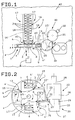
- Number 1 in Figures 1 and 2 indicates the output unit of a packing line indicated as a whole by 2 and for forming in known manner containers consisting of packets of cigarettes 3.
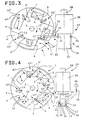
- Output unit 1 substantially comprises a conveying device or conveyor in turn comprising a wheel 4 rotating clockwise (in Figures 2 to 4) in constant steps (of 90° in the example shown) about a vertical axis 5, and presenting a number (four in the example shown) of angularly equidistant peripheral seats 6 for housing respective packets 3.
- a packet 3 is inserted inside a first seat 6 by a vertical-operating lift element 6' at an input station 7 at the top in Figures 2 to 4; and, at the same time, a vertical-operating lift element 8, moved back and forth by an actuating element 8' and cooperating with a counterpush element (not shown), expels another packet 3 from a second seat 6 diametrically opposite first seat 6 and at an output station 9 ( Figures 2 to 4).
- Wheel 4 rotates over a fixed disk element 4' coaxial with wheel 4 and presenting two openings (not shown) for the passage, through disk element 4', of lift elements 6' and 8 respectively.
- Each packet 3 is substantially in the form of a flat, elongated parallelepipedon, and seats 6 are so formed and arranged as to house packet 3 with the larger faces 10 (Figure 6) positioned horizontally, and the two smaller vertical lateral faces 11 positioned substantially radially in relation to wheel 4 ( Figure 4), so that lift element 8 acts on the bottom larger face 10 of each packet 3.
- each seat 6 of wheel 4 presents a substantially rectangular horizontal section reproducing the shape and size of the larger faces 10 of packet 3; is defined at two opposite sides by two parallel, vertical walls 12 ( Figure 4) perpendicular to the diameter of wheel 4; is defined by a vertical wall 12' perpendicularly connecting the two ends of walls 12 upstream in relation to the rotation direction of wheel 4; and presents an opening 6'' at the other end of walls 12, i.e. at the edge facing downstream in relation to the rotation direction of wheel 4.
- Each clamping element 12'' comprises a substantially horizontal lever 13 fitted at one end to a vertical pin 14 ( Figures 2 and 4) in turn fitted to wheel 4 and connected in known manner to actuating means (not shown) by which it is oscillated about its axis as described later on.
- the other end of each lever 13 is fitted rigidly, on the surface facing upstream in relation to the rotation direction of wheel 4, with a pad 15 of resilient material.
- Packets 3 are successively expelled from seats 6 of wheel 4 on to the bottom of a vertical stack 16 consisting of a number of packets 3 stacked one on top of the other with respective faces 10 contacting.
- the bottom of stack 16 is defined by lift element 8 ( Figure 1) which is moved back and forth vertically by a distance approximately equal to but no less than the distance between the two larger faces 10 of each packet 3.
- the portion of stack 16 over output station 9 is defined laterally, at two horizontally opposite sides and in known manner, by conveying means comprising two vertical conveyor belts 17 presenting respective transportation branches 18 moved intermittently upwards by drive means not shown.
- conveying means comprising two vertical conveyor belts 17 presenting respective transportation branches 18 moved intermittently upwards by drive means not shown.
- the whole comprising conveyor belts 17 and lift element 8 will also be referred to as a conveying device for conveying packets 3 along a path defined in Figure 1 by the longitudinal axis 16' of stack 16.
- supply device 20 comprises a roller 21 rotating anticlockwise in steps about a horizontal axis perpendicular to the Figure 1 plane, and which provides in known manner for withdrawing, and retaining by suction, single labels 19 from the bottom of a feedbox 22.
- Roller 21 successively feeds labels 19 to a supply device comprising a roller 23 rotating clockwise in steps about an axis 23' parallel to the rotation axis of roller 21, and which provides for successively feeding labels 19, retained by suction, to a known device for applying adhesive material and indicated schematically by block 24.
- Labels 19 coated on one surface with adhesive material are then fed by roller 23 to a station 25 for applying labels 19 to packets 3, and which is located along the path traveled by seats 6 as wheel 4 is rotated.
- rollers 21 and 23 rotate in steps of 180°.
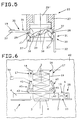
- roller 23 comprises two substantially cylindrical bodies 26 and 27 - respectively at the top and bottom in Figures 2 to 4 - coaxial with each other, connected to each other at their respective bases, and fitted coaxially to a hollow shaft 28 connected to drive members (not shown) for rotating it in steps as described with reference to roller 23.
- Cylindrical body 26 is larger in diameter than cylindrical body 27, and is located horizontally alongside, with a generating line substantially tangent to, the portion of wheel 4 at station 25 wherein labels 19 are applied to packets 3.
- Each two-armed lever 30 ( Figure 4) comprises a first arm 31 outside cylindrical body 27 and supporting a fork element 32 on its free end.
- Fork element 32 comprises two parallel prongs 33 constituting respective extensions of arm 31 and separated by a distance approximately equal to but no more than the length of label 19; and, close to the free ends of prongs 33, the surfaces of prongs 33 facing outwards, in use, of cylindrical body 27 present a number of holes 34 ( Figure 4) communicating via valve means 35 with a suction source indicated schematically by block 36.
- each two-armed lever 30 extends partially inside cylindrical body 27 through an opening 37' ( Figure 5), and supports a roller 38 engaging an actuating element comprising a fixed cam element 39 housed inside cylindrical body 27 and fitted coaxially to a fixed shaft 39' housed coaxially inside hollow shaft 28.
- retaining means for retaining labels 19.
- positioning means 40 for positioning packets 3 forming part of stack 16.
- positioning means 40 comprises a supporting member comprising a substantially vertical bar 41 pivoting at the top end on vertical wall 42 of the base of packing line 1, and rotating about a horizontal axis parallel to axis 23'; and the bottom end of each bar 41 supports an appendix 43 extending substantially horizontally towards the longitudinal axis of stack 16.
- Bars 41 ( Figure 6) are connected in known manner (not shown) to actuating means 44 for rotating bars 41 about their respective pivots and so moving appendixes 43 towards each other ( Figure 1) or away from each other ( Figure 6).
- appendixes 43 When brought towards each other, appendixes 43 are so positioned that their respective upper surfaces are slightly above the top larger faces 10 of packets 3 inside seats 6 of wheel 4.
- a packet 3 is inserted inside a seat 6 by lift element 6' at input station 7, and another packet 3 is expelled from a seat 6 by lift element 8 at output station 9.
- the labels 19 to be applied to packets 3 are withdrawn successively from the bottom of feedbox 22 and fed to roller 23 by roller 21; and each label 19 is fed by roller 23 to station 25 with its exposed surface coated at least partially with adhesive material applied by device 24.
- each label 19 on roller 21 is transferred to a fork element 32; and, upon transfer of label 19 from roller 21, the holes 34 in prongs 33 of the receiving fork element 32 are connected by valve element 35 to suction source 36, so that the two longitudinal ends of label 19 are gripped and retained by suction on the end portions of prongs 33.
- cam element 39 maintains the receiving fork element 32 against the cylindrical surface of body 27, in the position-shown to the right in Figure 2.
- cam element 39 rotates fork element 32 so that it is arrested perpendicular to axis 23', in the position shown to the center of Figure 2.
- wheel 4 When the fork element 32 in question reaches station 25, wheel 4 is stationary, but, immediately following the arrival of fork element 32, begins rotating and, before returning to the Figure 2 position, moves successively through the positions shown in Figures 3 and 4.
- disk element 4' presents a peripheral recess 4'' substantially at station 25 and of such a shape and size as to permit fork elements 32 to cooperate with packets 3 without interfering with disk element 4'.
- cam element 39 moves fork element 32 back to the Figure 4 position resting against the cylindrical surface of body 27.
- each packet 3 is pushed by lift element 8 between conveyor belts 17 as already described.
Applications Claiming Priority (2)
| Application Number | Priority Date | Filing Date | Title |
|---|---|---|---|
| IT93BO000518A IT1264296B1 (it) | 1993-12-23 | 1993-12-23 | Apparecchiatura per l'applicazione di etichette di sigillo a contenitori |
| ITBO930518 | 1993-12-23 |
Publications (2)
| Publication Number | Publication Date |
|---|---|
| EP0662423A1 EP0662423A1 (en) | 1995-07-12 |
| EP0662423B1 true EP0662423B1 (en) | 1998-04-15 |
Family
ID=11339373
Family Applications (1)
| Application Number | Title | Priority Date | Filing Date |
|---|---|---|---|
| EP94120533A Expired - Lifetime EP0662423B1 (en) | 1993-12-23 | 1994-12-23 | Device for applying sealing labels to containers |
Country Status (7)
| Country | Link |
|---|---|
| US (1) | US5573628A (it) |
| EP (1) | EP0662423B1 (it) |
| JP (1) | JPH07309318A (it) |
| CN (1) | CN1064017C (it) |
| BR (1) | BR9405211A (it) |
| DE (1) | DE69409622T2 (it) |
| IT (1) | IT1264296B1 (it) |
Families Citing this family (6)
| Publication number | Priority date | Publication date | Assignee | Title |
|---|---|---|---|---|
| IT1299982B1 (it) * | 1998-04-22 | 2000-04-04 | Gd Spa | Metodo per la realizzazione di pacchetti di sigarette ed impianto per l'attuazione di tale metodo. |
| ITBO20040589A1 (it) | 2004-09-22 | 2004-12-22 | Gd Spa | Metodo e unita' per applicare un'etichetta ad un articolo |
| ITPR20050011A1 (it) * | 2005-03-25 | 2006-09-26 | Sig Simonazzi Spa | Valvola per fluidi. |
| ITBO20070129A1 (it) * | 2007-02-27 | 2007-05-29 | Gd Spa | Macchina e metodo per l' applicazione di etichette a pacchetti. |
| DE102015001593A1 (de) * | 2015-02-05 | 2016-08-11 | Focke & Co. (Gmbh & Co. Kg) | Vorrichtung und Verfahren zum Herstellen von quaderförmigen Packungen für Zigaretten |
| CN105035443B (zh) * | 2015-06-29 | 2017-11-28 | 重庆永林机械设备有限公司 | 一种用于块状物料的自动贴标机 |
Family Cites Families (14)
| Publication number | Priority date | Publication date | Assignee | Title |
|---|---|---|---|---|
| US1185848A (en) * | 1915-03-15 | 1916-06-06 | American Mach & Foundry | Packing-machine. |
| US1425250A (en) * | 1917-10-10 | 1922-08-08 | Automatic Packing & Labeling C | Machine for applying stamps and the like to packages or containers |
| US1405190A (en) * | 1921-04-04 | 1922-01-31 | Durkee | Labeling machine |
| US1939507A (en) * | 1931-07-13 | 1933-12-12 | Mason James | Machine for applying bands or stamps to packets |
| US2115061A (en) * | 1932-12-19 | 1938-04-26 | Anchor Cap & Closure Corp | Labeling machine attachment |
| US2005802A (en) * | 1933-02-06 | 1935-06-25 | Oslund Brothers Machine Compan | Labeling machine |
| GB531304A (en) * | 1938-08-09 | 1941-01-01 | Johann Carl Mueller | Process and apparatus for applying revenue duty labels or the like to the narrow sides of packages by means of adhesive |
| US2267549A (en) * | 1939-12-15 | 1941-12-23 | Wilhelm B Bronander | Machine for applying labels to packages |
| DE2932621A1 (de) * | 1979-08-11 | 1981-02-26 | Schmermund Maschf Alfred | Vorrichtung zum anheften von etiketten |
| IT1166432B (it) * | 1982-03-13 | 1987-04-29 | Molins Plc | Apparecchio per applicare etichette e simili su oggetti, in particolate pacchetti di sigarette |
| DE3339555A1 (de) * | 1983-11-02 | 1985-05-09 | Maschinenfabrik Alfred Schmermund Gmbh & Co, 5820 Gevelsberg | Vorrichtung zum anbringen von siegelmarken an zigarettenpackungen |
| DE3512611A1 (de) * | 1985-04-06 | 1986-10-16 | Focke & Co (GmbH & Co), 2810 Verden | Verfahren und vorrichtung zum verpacken von insbesondere zigaretten |
| IT1186574B (it) * | 1985-06-14 | 1987-12-04 | Gd Spa | Dispositivo di alimentazione di bollini di stato in una macchina impacchettatrice di segarette |
| JP3354588B2 (ja) * | 1992-03-31 | 2002-12-09 | 日本たばこ産業株式会社 | 連続シール貼付け装置 |
-
1993
- 1993-12-23 IT IT93BO000518A patent/IT1264296B1/it active IP Right Grant
-
1994
- 1994-12-15 US US08/356,873 patent/US5573628A/en not_active Expired - Lifetime
- 1994-12-22 CN CN94119194.XA patent/CN1064017C/zh not_active Expired - Fee Related
- 1994-12-22 BR BR9405211A patent/BR9405211A/pt not_active IP Right Cessation
- 1994-12-23 EP EP94120533A patent/EP0662423B1/en not_active Expired - Lifetime
- 1994-12-23 DE DE69409622T patent/DE69409622T2/de not_active Expired - Fee Related
- 1994-12-26 JP JP6323404A patent/JPH07309318A/ja active Pending
Also Published As
| Publication number | Publication date |
|---|---|
| EP0662423A1 (en) | 1995-07-12 |
| CN1064017C (zh) | 2001-04-04 |
| JPH07309318A (ja) | 1995-11-28 |
| DE69409622D1 (de) | 1998-05-20 |
| ITBO930518A1 (it) | 1995-06-23 |
| IT1264296B1 (it) | 1996-09-23 |
| CN1107796A (zh) | 1995-09-06 |
| BR9405211A (pt) | 1995-08-01 |
| DE69409622T2 (de) | 1998-10-01 |
| ITBO930518A0 (it) | 1993-12-23 |
| US5573628A (en) | 1996-11-12 |
Similar Documents
| Publication | Publication Date | Title |
|---|---|---|
| US20060076111A1 (en) | Method and unit for applying a label to an article | |
| EP0805116B1 (en) | Product conveying device | |
| US4655871A (en) | Device for feeding revenue stamps on a cigarette packing machine | |
| US5641053A (en) | Equally spaced product conveying method and line | |
| US4564412A (en) | Method of and apparatus for applying seal stamps | |
| US6213284B1 (en) | Method and unit for transferring articles | |
| EP0956239B1 (en) | A device and a method for the application of detachable coupons to substantially parallelepiped packets | |
| US5009741A (en) | Method and device for the application of revenue stamps to packs | |
| CN108298303B (zh) | 用于传送泡罩包装的方法 | |
| EP0662423B1 (en) | Device for applying sealing labels to containers | |
| US5409098A (en) | Apparatus for the transport of cigarette packs | |
| US7192502B2 (en) | Method and device for applying a label to a packet | |
| US4620891A (en) | Applying labels to packets | |
| US20070079576A1 (en) | Method and unit for transferring a product on an intermittent packing machine | |
| JPH021210Y2 (it) | ||
| US6189296B1 (en) | Method and machine for packing a product | |
| EP0792810A1 (en) | Output unit for a continuous wrapping machine | |
| US20020056258A1 (en) | Method of and apparatus for manipulating coupons and the like in cigarette packing machines | |
| US5497598A (en) | Equipment for the application of seal labels to containers | |
| EP1352835A2 (en) | Device for transferring articles and wrapping machine comprising such a device | |
| EP1013557A1 (en) | Method of feeding collars to a continuous packing line for producing rigid packets of cigarettes | |
| EP0555852A1 (en) | Overwrapping machine for continuously packing products in tubular wrappings | |
| EP0924136B1 (en) | A method for applying slips of materials to substantially parallelepiped packets | |
| US5806279A (en) | Method and unit for packing products | |
| EP1145962B1 (en) | A method and a device for applying labels to packets of cigarettes |
Legal Events
| Date | Code | Title | Description |
|---|---|---|---|
| PUAI | Public reference made under article 153(3) epc to a published international application that has entered the european phase |
Free format text: ORIGINAL CODE: 0009012 |
|
| AK | Designated contracting states |
Kind code of ref document: A1 Designated state(s): DE FR GB IT |
|
| 17P | Request for examination filed |
Effective date: 19951228 |
|
| 17Q | First examination report despatched |
Effective date: 19960906 |
|
| GRAG | Despatch of communication of intention to grant |
Free format text: ORIGINAL CODE: EPIDOS AGRA |
|
| GRAG | Despatch of communication of intention to grant |
Free format text: ORIGINAL CODE: EPIDOS AGRA |
|
| GRAH | Despatch of communication of intention to grant a patent |
Free format text: ORIGINAL CODE: EPIDOS IGRA |
|
| GRAH | Despatch of communication of intention to grant a patent |
Free format text: ORIGINAL CODE: EPIDOS IGRA |
|
| GRAA | (expected) grant |
Free format text: ORIGINAL CODE: 0009210 |
|
| AK | Designated contracting states |
Kind code of ref document: B1 Designated state(s): DE FR GB IT |
|
| ITF | It: translation for a ep patent filed |
Owner name: STUDIO TORTA S.R.L. |
|
| REF | Corresponds to: |
Ref document number: 69409622 Country of ref document: DE Date of ref document: 19980520 |
|
| ET | Fr: translation filed | ||
| PLBE | No opposition filed within time limit |
Free format text: ORIGINAL CODE: 0009261 |
|
| STAA | Information on the status of an ep patent application or granted ep patent |
Free format text: STATUS: NO OPPOSITION FILED WITHIN TIME LIMIT |
|
| 26N | No opposition filed | ||
| REG | Reference to a national code |
Ref country code: GB Ref legal event code: IF02 |
|
| PGFP | Annual fee paid to national office [announced via postgrant information from national office to epo] |
Ref country code: IT Payment date: 20061231 Year of fee payment: 13 |
|
| PGFP | Annual fee paid to national office [announced via postgrant information from national office to epo] |
Ref country code: GB Payment date: 20071227 Year of fee payment: 14 |
|
| PGFP | Annual fee paid to national office [announced via postgrant information from national office to epo] |
Ref country code: DE Payment date: 20080131 Year of fee payment: 14 |
|
| PGFP | Annual fee paid to national office [announced via postgrant information from national office to epo] |
Ref country code: FR Payment date: 20071217 Year of fee payment: 14 |
|
| GBPC | Gb: european patent ceased through non-payment of renewal fee |
Effective date: 20081223 |
|
| PG25 | Lapsed in a contracting state [announced via postgrant information from national office to epo] |
Ref country code: IT Free format text: LAPSE BECAUSE OF NON-PAYMENT OF DUE FEES Effective date: 20071223 |
|
| REG | Reference to a national code |
Ref country code: FR Ref legal event code: ST Effective date: 20090831 |
|
| PG25 | Lapsed in a contracting state [announced via postgrant information from national office to epo] |
Ref country code: DE Free format text: LAPSE BECAUSE OF NON-PAYMENT OF DUE FEES Effective date: 20090701 |
|
| PG25 | Lapsed in a contracting state [announced via postgrant information from national office to epo] |
Ref country code: GB Free format text: LAPSE BECAUSE OF NON-PAYMENT OF DUE FEES Effective date: 20081223 |
|
| PG25 | Lapsed in a contracting state [announced via postgrant information from national office to epo] |
Ref country code: FR Free format text: LAPSE BECAUSE OF NON-PAYMENT OF DUE FEES Effective date: 20081231 |