EP0659225B1 - Roll formed metal member with reinforcement indentations - Google Patents
Roll formed metal member with reinforcement indentations Download PDFInfo
- Publication number
- EP0659225B1 EP0659225B1 EP92923637A EP92923637A EP0659225B1 EP 0659225 B1 EP0659225 B1 EP 0659225B1 EP 92923637 A EP92923637 A EP 92923637A EP 92923637 A EP92923637 A EP 92923637A EP 0659225 B1 EP0659225 B1 EP 0659225B1
- Authority
- EP
- European Patent Office
- Prior art keywords
- web
- formations
- triangular
- edge
- generally
- Prior art date
- Legal status (The legal status is an assumption and is not a legal conclusion. Google has not performed a legal analysis and makes no representation as to the accuracy of the status listed.)
- Expired - Lifetime
Links
Images


Classifications
-
- E—FIXED CONSTRUCTIONS
- E04—BUILDING
- E04C—STRUCTURAL ELEMENTS; BUILDING MATERIALS
- E04C3/00—Structural elongated elements designed for load-supporting
- E04C3/02—Joists; Girders, trusses, or trusslike structures, e.g. prefabricated; Lintels; Transoms; Braces
- E04C3/04—Joists; Girders, trusses, or trusslike structures, e.g. prefabricated; Lintels; Transoms; Braces of metal
- E04C3/06—Joists; Girders, trusses, or trusslike structures, e.g. prefabricated; Lintels; Transoms; Braces of metal with substantially solid, i.e. unapertured, web
- E04C3/065—Joists; Girders, trusses, or trusslike structures, e.g. prefabricated; Lintels; Transoms; Braces of metal with substantially solid, i.e. unapertured, web with special adaptations for the passage of cables or conduits through the web
-
- E—FIXED CONSTRUCTIONS
- E04—BUILDING
- E04C—STRUCTURAL ELEMENTS; BUILDING MATERIALS
- E04C3/00—Structural elongated elements designed for load-supporting
- E04C3/02—Joists; Girders, trusses, or trusslike structures, e.g. prefabricated; Lintels; Transoms; Braces
- E04C3/04—Joists; Girders, trusses, or trusslike structures, e.g. prefabricated; Lintels; Transoms; Braces of metal
- E04C3/08—Joists; Girders, trusses, or trusslike structures, e.g. prefabricated; Lintels; Transoms; Braces of metal with apertured web, e.g. with a web consisting of bar-like components; Honeycomb girders
- E04C3/09—Joists; Girders, trusses, or trusslike structures, e.g. prefabricated; Lintels; Transoms; Braces of metal with apertured web, e.g. with a web consisting of bar-like components; Honeycomb girders at least partly of bent or otherwise deformed strip- or sheet-like material
-
- E—FIXED CONSTRUCTIONS
- E04—BUILDING
- E04C—STRUCTURAL ELEMENTS; BUILDING MATERIALS
- E04C3/00—Structural elongated elements designed for load-supporting
- E04C3/02—Joists; Girders, trusses, or trusslike structures, e.g. prefabricated; Lintels; Transoms; Braces
- E04C3/04—Joists; Girders, trusses, or trusslike structures, e.g. prefabricated; Lintels; Transoms; Braces of metal
- E04C2003/0404—Joists; Girders, trusses, or trusslike structures, e.g. prefabricated; Lintels; Transoms; Braces of metal beams, girders, or joists characterised by cross-sectional aspects
- E04C2003/0408—Joists; Girders, trusses, or trusslike structures, e.g. prefabricated; Lintels; Transoms; Braces of metal beams, girders, or joists characterised by cross-sectional aspects characterised by assembly or the cross-section
- E04C2003/0421—Joists; Girders, trusses, or trusslike structures, e.g. prefabricated; Lintels; Transoms; Braces of metal beams, girders, or joists characterised by cross-sectional aspects characterised by assembly or the cross-section comprising one single unitary part
-
- E—FIXED CONSTRUCTIONS
- E04—BUILDING
- E04C—STRUCTURAL ELEMENTS; BUILDING MATERIALS
- E04C3/00—Structural elongated elements designed for load-supporting
- E04C3/02—Joists; Girders, trusses, or trusslike structures, e.g. prefabricated; Lintels; Transoms; Braces
- E04C3/04—Joists; Girders, trusses, or trusslike structures, e.g. prefabricated; Lintels; Transoms; Braces of metal
- E04C2003/0404—Joists; Girders, trusses, or trusslike structures, e.g. prefabricated; Lintels; Transoms; Braces of metal beams, girders, or joists characterised by cross-sectional aspects
- E04C2003/0426—Joists; Girders, trusses, or trusslike structures, e.g. prefabricated; Lintels; Transoms; Braces of metal beams, girders, or joists characterised by cross-sectional aspects characterised by material distribution in cross section
- E04C2003/0434—Joists; Girders, trusses, or trusslike structures, e.g. prefabricated; Lintels; Transoms; Braces of metal beams, girders, or joists characterised by cross-sectional aspects characterised by material distribution in cross section the open cross-section free of enclosed cavities
-
- E—FIXED CONSTRUCTIONS
- E04—BUILDING
- E04C—STRUCTURAL ELEMENTS; BUILDING MATERIALS
- E04C3/00—Structural elongated elements designed for load-supporting
- E04C3/02—Joists; Girders, trusses, or trusslike structures, e.g. prefabricated; Lintels; Transoms; Braces
- E04C3/04—Joists; Girders, trusses, or trusslike structures, e.g. prefabricated; Lintels; Transoms; Braces of metal
- E04C2003/0404—Joists; Girders, trusses, or trusslike structures, e.g. prefabricated; Lintels; Transoms; Braces of metal beams, girders, or joists characterised by cross-sectional aspects
- E04C2003/0443—Joists; Girders, trusses, or trusslike structures, e.g. prefabricated; Lintels; Transoms; Braces of metal beams, girders, or joists characterised by cross-sectional aspects characterised by substantial shape of the cross-section
- E04C2003/046—L- or T-shaped
-
- E—FIXED CONSTRUCTIONS
- E04—BUILDING
- E04C—STRUCTURAL ELEMENTS; BUILDING MATERIALS
- E04C3/00—Structural elongated elements designed for load-supporting
- E04C3/02—Joists; Girders, trusses, or trusslike structures, e.g. prefabricated; Lintels; Transoms; Braces
- E04C3/04—Joists; Girders, trusses, or trusslike structures, e.g. prefabricated; Lintels; Transoms; Braces of metal
- E04C2003/0404—Joists; Girders, trusses, or trusslike structures, e.g. prefabricated; Lintels; Transoms; Braces of metal beams, girders, or joists characterised by cross-sectional aspects
- E04C2003/0443—Joists; Girders, trusses, or trusslike structures, e.g. prefabricated; Lintels; Transoms; Braces of metal beams, girders, or joists characterised by cross-sectional aspects characterised by substantial shape of the cross-section
- E04C2003/0473—U- or C-shaped
-
- Y—GENERAL TAGGING OF NEW TECHNOLOGICAL DEVELOPMENTS; GENERAL TAGGING OF CROSS-SECTIONAL TECHNOLOGIES SPANNING OVER SEVERAL SECTIONS OF THE IPC; TECHNICAL SUBJECTS COVERED BY FORMER USPC CROSS-REFERENCE ART COLLECTIONS [XRACs] AND DIGESTS
- Y10—TECHNICAL SUBJECTS COVERED BY FORMER USPC
- Y10T—TECHNICAL SUBJECTS COVERED BY FORMER US CLASSIFICATION
- Y10T428/00—Stock material or miscellaneous articles
- Y10T428/12—All metal or with adjacent metals
- Y10T428/12354—Nonplanar, uniform-thickness material having symmetrical channel shape or reverse fold [e.g., making acute angle, etc.]
-
- Y—GENERAL TAGGING OF NEW TECHNOLOGICAL DEVELOPMENTS; GENERAL TAGGING OF CROSS-SECTIONAL TECHNOLOGIES SPANNING OVER SEVERAL SECTIONS OF THE IPC; TECHNICAL SUBJECTS COVERED BY FORMER USPC CROSS-REFERENCE ART COLLECTIONS [XRACs] AND DIGESTS
- Y10—TECHNICAL SUBJECTS COVERED BY FORMER USPC
- Y10T—TECHNICAL SUBJECTS COVERED BY FORMER US CLASSIFICATION
- Y10T428/00—Stock material or miscellaneous articles
- Y10T428/12—All metal or with adjacent metals
- Y10T428/12361—All metal or with adjacent metals having aperture or cut
- Y10T428/12368—Struck-out portion type
-
- Y—GENERAL TAGGING OF NEW TECHNOLOGICAL DEVELOPMENTS; GENERAL TAGGING OF CROSS-SECTIONAL TECHNOLOGIES SPANNING OVER SEVERAL SECTIONS OF THE IPC; TECHNICAL SUBJECTS COVERED BY FORMER USPC CROSS-REFERENCE ART COLLECTIONS [XRACs] AND DIGESTS
- Y10—TECHNICAL SUBJECTS COVERED BY FORMER USPC
- Y10T—TECHNICAL SUBJECTS COVERED BY FORMER US CLASSIFICATION
- Y10T428/00—Stock material or miscellaneous articles
- Y10T428/12—All metal or with adjacent metals
- Y10T428/1241—Nonplanar uniform thickness or nonlinear uniform diameter [e.g., L-shape]
Definitions
- the invention relates to a roll formed metal member having generally axially located recesses and defining transverse struts therebetween.
- the invention further relates to a metal member having generally three-sided indentations formed therein adjacent to the ends of the struts.
- Roll formed metal members may be used for a variety of purposes, as either structural load bearing members, or as beams of various kinds, or in many non-load bearing applications.
- Such members may be of a variety of cross-sections.
- One typical member has a generally C shaped cross-section.
- Other members may have a cross-section similar to a Z, and other members may be of a T shaped cross section or an I shaped cross section to name only a few.
- the member is formed with generally triangular or trapezoidal shaped openings, which openings define between them generally diagonal struts. Edge flanges were formed along either side of the struts and around the sides of the openings. Roll formed continuous angle formations were formed along either side of the member.
- Such hot rolled structural members are formed in various thicknesses and dimensions for various different applications. Clearly, the same observations apply namely that if the hot rolled members can be increased in strength by certain formations, which are formed in them, then the thickness of metal in the member may be reduced thereby reducing its weight and its cost.
- the invention comprises a metal member having at least one edge formation, and web extending from said edge formation, and comprising:
- the invention further comprises a metal member as described and define a base parallel with a said edge of said web, and two sides extending diagonally, and wherein curved base corners extend between said base and said sides, and wherein said sides meet at a curved apex corner, and wherein said apex corner of one of said triangular formations and an adjacent curved base corner of another said triangular formation, define between them an enlarged end portion at each end of said diagonal strut.
- the invention further comprises a metal member as described and wherein said three-sided indentations comprise a first base side which is linear and generally parallel with a said edge of said web, a second linear angled side extending from said base linear side, and a third curved side extending from said base linear side and meeting said second linear side at an apex, and wherein said apex extends into said diagonal strut portion of said web.
- the invention further comprises a metal member as described and wherein said third curved side of said three-sided indentation is spaced from the adjacent said curved base corner of said triangular formation, thereby defining a generally curved strut root portion.
- the invention further comprises a metal member as described and wherein said portions of said flange formations around said corners of said triangular formations lie at an angle of between 75° and 85° relative to the plane of said web portion.
- the invention further comprises a metal member as described and wherein said second linear edge portion of said three-sided indentations extends generally parallel to and spaced from a linear edge portion of one of said triangular formations, whereby to define a substantially linear strut root portion formed from said web and merging into said respective diagonal strut, and spaced from said curved strut root portion, whereby each said diagonal strut extends from both a generally curved strut root portion and a linear strut root portion formed from said web.
- the invention further comprises a metal member as described and wherein said corner flange formations are of generally curved shape in section.
- the invention further comprises a metal member as described and wherein said member is a hot rolled steel member, having a web portion, and wherein said triangular formations and said indentations are formed in said web portion.
- the invention further comprises a metal member as described and wherein said member is a cold rolled steel strip member, and including two said edge formations, extending along opposite edges of said web, defining a generally channel shape in cross section, and wherein said triangular formations and said flange formations extend from said web on the same side as said edge formation.
- the invention further comprises a metal member as described and having an edge formation extending to one side of said web, and wherein said flange formations around said triangular formations, and wherein said indentations, both extend to the opposite side of said web.
- the invention further comprises a metal member as described and wherein said triangular formations define triangular openings.
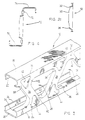
- the invention will be seen to comprise a metal member indicated generally as 10.
- the member 10 may be considered simply as a lightweight strut, or as a load bearing stud, or as a transverse beam, and may be used in various thicknesses and in various load bearing specifications. In this case it will be seen to be formed of cold rolled sheet metal, typically steel (or other ferrous or non-ferrous metals).
- the member 10 consists of a web portion 12, defining two web edges 14 and 16.
- edges 14 and 16 are right angular spacer strips 18 and 20, having in-turned corners 22 and 24.
- a series of recesses, in this case, generally triangular shaped openings 26a-26c are formed in web 12, at spaced intervals.
- Alternate recesses 26 face in opposite directions, so as to define generally transverse, diagonal struts 28 there-between extending across the web between one side edge 14 and the other side edge 16 of the web 12.
- Edge flange formations 30, 32, and 34 are linear openings 26 define base corners 26a -26b and an apex corner 26c.
- curved flange portions are formed at 36, 38 and 40. The flanges in fact are continuous, and are formed at an angle to the plane of the web 12.
- each of the strut portions 28 between adjacent openings 26 have a general channel shape in cross-section.
- the linear flange portions 30, 32 and 34 are somewhat deeper than the corner flange portions 36, 38 and 40 ( Figures 2a and 2b).
- the two remaining linear flange portions 30 and 32 meet at the curved flange portion 40, which is herein termed the apex of the opening.
- each end of each strut 28 is thus somewhat enlarged, and is termed herein the root portion of the strut, where it merges with its adjacent edge 14 or 16 of web 12 respectively.
- Depression 42 has a base linear side 46, and an angled linear side 48, and a generally curved side 50.
- depression 44 has a linear base side 52, and a linear angled side 54 and a curved side 56.
- the linear angled side 48 is spaced from the edge flange 32 of the adjacent opening 26, and is essentially parallel to it.
- the curved side 50 of depression 42 is spaced from the curved flange 38 of the adjacent opening 26, and is curved in such way as to essentially complement the curvature of the flange 38 around the corner of the opening.
- the depression 44 is essentially a mirror image, in layout, as compared with the depression 42.
- the depressions 42-44 define linear strut root portions 50-60 and curved strut root portions 62-64.
- Each of the indentations 42-44 define respective apices 66 and 68, extending from the root portions inwardly along the length of their respective diagonal struts 28.
- a metal member when formed with these formations is found to possess greatly increased rigidity across the width of the web 12 i.e. from one edge 14 to the other edge 16, as compared with earlier metal members.
- the metal member 70 has a generally Z-shaped configuration.
- the metal member 70 has a web portion 72 similar to the web 12 of the embodiment of Figures 1, 2 and 3.
- the member 70 has facing panel members 74 and 76, which are offset on opposite sides of the web 72.
- the metal member indicated generally as 80 has a web portion 82, and edges 84-86.
- Support panels 88 and 90 extend at right angles from the edges 84 and 86, as in the embodiment of Figures 1, 2 and 3.
- openings 92-92 formed through the member at spaced intervals, and being alternately reversed relative to one another. They may also be described as being “generally” triangular in shape. However, it will be seen that their configuration is somewhat in the form of a distorted triangle. Thus these openings have generally linear side flange formations namely the base flange formation 94 and the two side flange formations 96 and 98.
- a generally scoop-shaped corner flange 104 is formed.
- the scoop formations may be either generally curved in section ( Figure 6) or may be angular in shape, so as to define a first more steeply angled portion and a second less steeply angled portion.
- the general objective being, in either the scoop formation or the angled formation, to insure that the scoop shaped flange portions extending around the corners of the triangles are formed in such a manner as to provide an adequate extent of metal throughout the corner flange portions, without deforming them out of the plane of the web to the extent that it would cause weakening of the flange portions in these corner areas.
- corner flanges 100, 102, 104 appear somewhat in the shape of a scoop or saucer section in elevation, compared with the linear flanges 94, 96, 98 which are substantially deflected out of the plane of the web 82.
- the metal members 80 define diagonal struts 106-106 extending between the openings 92-92. At each end root portion of the diagonal struts 106, there are formed generally three-sided depressions or indentations 108 and 110. As before, each of the three-sided depressions 108, 110 define linear base edges 112, and linear side edges 114, and generally curved side edges 116.
- the base linear side edges 112 are substantially parallel to the edges 84 and 86 of the web 82.
- the linear side edges 114 are substantially parallel to the side flanges 96.
- the curved side edges 116 of the depressions 108 are curved so as to be complementary to the curved flanges 100 of the openings 92.
- All of the sections may be materially increased in strength by the use of the invention, in which generally triangular openings are formed, which are all alternately reversed relative to one another as has been described in the embodiments of Figures 1 to 6.
- depressions are formed, adjacent the ends of the struts defined by the triangular opening, and flanges are formed around the triangular opening, in the same manner as is illustrated in Figures 1-6.
- sections such as Figures 7, 8, 9 and 10 will be formed of hot rolled ferrous and non-ferrous metals.
- the strength of such metal members can be greatly increased by the use of the invention, and this will either increase the strength or permit the use of such metal members having a reduced metal content, to provide the same degree of load bearing capacity. In either case, substantial advantages will be achieved in accordance with the invention.
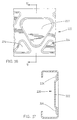
- FIG. 11 and 12 illustrate two different forms of channel.
- Figures 13 and 14 illustrate two different forms of cold formed metal sections, (described below) which may be desirable in some cases.
- substantial improvements in load bearing capacity can be achieved, and/or substantial reductions can be achieved in the thickness of the metal required to produce an equivalent load bearing capacity.
- the invention can be applied to a wide variety of different sections of metal members (both ferrous and non-ferrous) as mentioned above.
- the invention can be applied, for example, to hot rolled metal members.
- hot rolled metal members have less complex sections than cold rolled members.
- Typical hot rolled metal sections are shown in Figures 7, 8, 9 and 10.
- a typical hot rolled section may be in the shape of what is known as an I-beam 120.
- Such an I-Beam will have a central planar web 122, and two transverse edge formations 124.
- triangular openings 126 would be formed in the central web, defining struts 128.
- triangular depressions 130 such as those described above would be formed in the web at either end of the depressions.
- the beam 132 of Figure 8 and the beam 134 of Figure 9 and the beam 136 of Figure 10 would all have similar triangular openings, and flanges and depressions, as shown.
- such depressions, and the flanges surrounding the openings could be formed offset alternately to one side and to the other of the web, if this were desirable.
- the metal member 132 is in the form of a simple L shaped angle, having a web 134, and a right angular flange portion 136. Triangular openings as before, could be formed. Triangular openings are shown formed through the web, and triangular indentations are formed in the web.
- FIG. 9 Another typical hot rolled section is shown in Figure 9, in the form of a simple channel 140.
- a simple channel 140 Such a member would have a web 144, and two edge flanges 146.
- Triangular openings 148 are formed in the web, and triangular indentations 149 are formed at either ends of the struts defined by the triangular openings.
- the beam 150 of Figure 10 is a simple T-section having similar triangular openings and flanges and depressions as in the case of Figures 7, 8 and 9.
- a simple cold rolled channel 152 is illustrated, having a base wall 157, and having two side webs 154.
- Triangular formations 156 are formed in the two side webs and triangular depressions 158 are formed in the webs as shown.
- Figure 12 illustrates another form of a cold rolled section, which is essentially a box like section 160, having a base wall 162 side webs 164, and two inturned walls 166.
- triangular openings of 168 are formed in the two side webs and triangular indentations 170 are formed as shown.
- the base wall 174 has a generally double right angular bend 176, designed for a particular application.
- Side webs 178 and 180 of differing widths extend from the base wall.
- One or both of the side webs are formed with triangular openings 182 and triangular indentations 183 as shown.
- Figure 14 illustrates an alternate form of channel 184 having a base wall 186, and side walls 188.
- Triangular openings 190 and depressions 192 are formed in base wall 186.
- Figure 15 illustrates a further alternate form of member 200 having a web 202, and side panels 204 extending to one side. Triangular openings 206 are formed but with their flanges 208 extending on the opposite side of web 202.
- Depressions 210 are also formed, in web 202.
- openings and to "openings” throughout the document is deemed to include recesses formed in the web, with or without the removal of the metal therefrom.
- metal member 220 of generally similar design to the metal member of Figure 5.
- the recesses 221 in this case of generally triangular shape, are formed as depressions in the metal, but without any metal being removed.
- This member also has similar generally triangular reinforcement depressions 224 on either side of the central larger depression 222, giving the advantages described above in connection with the earlier embodiments.
- FIG. 18 A further embodiment is illustrated in Figures 18 and 19.
- the metal member 230 is formed with recesses 232, which are circular in shape, and from which the metal has been removed.
- An annular edge flange 234 is formed around each opening 232.
- Generally triangular depressions 236-236 are formed in the web between adjacent recesses 232.
- struts 238 are formed between each of the recesses 232, each of which have diverging root portions 240-240.
- the member 230 is also formed with right angular side flanges 242-242, having inturned edges 244-244.
- Transverse reinforcement ribs 246 are formed in the side flanges 242, and merging reinforcing ribs 248 are formed in the web, and merged with the edges of triangular depressions 236.
- the web is itself made rigid by the struts 238 and the flanges 234 and the depressions 236, and the side flanges 242 are further reinforced by the transverse ribs 246 and 248.
- FIG. 20 A further embodiment is shown in Figure 20.
- the metal member 250 has central circular recesses 252 similar to that illustrated in Figure 18, with annular flange 254.
- the general appearance of the web portion of the member 250 is similar to that of Figure 18, and the member is formed with generally triangular reinforcement depressions 256-256 between adjacent recesses 252, thereby providing struts 258 extending therebetween, having great rigidity.
- Side flanges 260 extend on either side of the web normal thereto, and have generally axial central depressions 262 formed therein, giving the member enhanced properties in certain respects.
- FIGs 21 and 22 illustrate modifications of the embodiment of Figures 18 and 19.
- the modification in this case is that the central annular recesses 272 have not had metal removed, and consequently simply define annular side walls 274.
- Struts 276 are formed between the recesses.
- Triangular depressions 278 are formed at either end of the struts 276, thereby providing divergent strut roots.
- Side flanges 280 extend upwardly from the web normal thereto, and are reinforced by transverse ribs 282 and 284.
- Figure 23 illustrates a further embodiment generally similar to the embodiment of Figure 20.
- the metal member 290 has a central circular recess 292 again without metal removed.
- An annular flange 294 is formed around the recess 292.
- Triangular depressions 296 are formed in the web between adjacent recesses 292.
- the side flanges 298 of the member 290 are generally similar in shape to the side flanges of the member 250 of Figure 20.
- Figures 24 and 25 illustrate a further modified embodiment.
- the metal member 300 is of generally similar design to the member 80 illustrated in Figures 5 and 6. It has central recesses 302 of generally triangular shape, having side flanges 304, and corner flanges 306 of generally scoop shape. Struts 308 are defined between the triangular recesses 302, and at each end of the struts, triangular reinforcement depressions 310 are formed, thereby providing generally divergent strut roots.
- Side flanges 312 are formed normal to the web, and are formed with central reinforcement depressions 314.
Landscapes
- Architecture (AREA)
- Engineering & Computer Science (AREA)
- Civil Engineering (AREA)
- Structural Engineering (AREA)
- Rod-Shaped Construction Members (AREA)
- Rolls And Other Rotary Bodies (AREA)
- Absorbent Articles And Supports Therefor (AREA)
- Nonwoven Fabrics (AREA)
- Heat Treatment Of Sheet Steel (AREA)
- Bending Of Plates, Rods, And Pipes (AREA)
- Metal Rolling (AREA)
- Threshing Machine Elements (AREA)
- Crystals, And After-Treatments Of Crystals (AREA)
- Toys (AREA)
- Laminated Bodies (AREA)
- Registering, Tensioning, Guiding Webs, And Rollers Therefor (AREA)
- Moulds For Moulding Plastics Or The Like (AREA)
- Injection Moulding Of Plastics Or The Like (AREA)
Applications Claiming Priority (3)
| Application Number | Priority Date | Filing Date | Title |
|---|---|---|---|
| CA2077429 | 1992-09-02 | ||
| CA002077429A CA2077429C (en) | 1992-09-02 | 1992-09-02 | Roll formed metal member |
| PCT/CA1992/000514 WO1994005872A1 (en) | 1992-09-02 | 1992-11-25 | Roll formed metal member with reinforcement indentations |
Publications (2)
| Publication Number | Publication Date |
|---|---|
| EP0659225A1 EP0659225A1 (en) | 1995-06-28 |
| EP0659225B1 true EP0659225B1 (en) | 1998-10-07 |
Family
ID=4150364
Family Applications (1)
| Application Number | Title | Priority Date | Filing Date |
|---|---|---|---|
| EP92923637A Expired - Lifetime EP0659225B1 (en) | 1992-09-02 | 1992-11-25 | Roll formed metal member with reinforcement indentations |
Country Status (20)
| Country | Link |
|---|---|
| US (1) | US5527625A (es) |
| EP (1) | EP0659225B1 (es) |
| JP (1) | JP3005293B2 (es) |
| CN (1) | CN1049371C (es) |
| AT (1) | ATE171995T1 (es) |
| AU (1) | AU689437B2 (es) |
| CA (1) | CA2077429C (es) |
| DE (1) | DE69227260T2 (es) |
| DK (1) | DK0659225T3 (es) |
| ES (1) | ES2124744T3 (es) |
| HK (1) | HK1007668A1 (es) |
| IL (1) | IL106846A (es) |
| IN (1) | IN182049B (es) |
| MX (1) | MX9305328A (es) |
| MY (1) | MY110035A (es) |
| SG (1) | SG48248A1 (es) |
| TW (1) | TW322435B (es) |
| WO (1) | WO1994005872A1 (es) |
| ZA (1) | ZA935954B (es) |
| ZW (1) | ZW10393A1 (es) |
Families Citing this family (80)
| Publication number | Priority date | Publication date | Assignee | Title |
|---|---|---|---|---|
| US5669197A (en) * | 1991-06-03 | 1997-09-23 | Bodnar; Ernest Robert | Sheet metal structural member |
| SE502870C2 (sv) * | 1991-11-26 | 1996-02-05 | Volvo Ab | Föstärkningsbalk, exempelvis för fordonskarosseridetaljer |
| US5605024A (en) * | 1994-02-07 | 1997-02-25 | Sucato; Edward | Stud assembly |
| US5687538A (en) * | 1995-02-14 | 1997-11-18 | Super Stud Building Products, Inc. | Floor joist with built-in truss-like stiffner |
| US6012256A (en) * | 1996-09-11 | 2000-01-11 | Programmatic Structures Inc. | Moment-resistant structure, sustainer and method of resisting episodic loads |
| IT1290903B1 (it) * | 1997-01-29 | 1998-12-14 | Massimo Ferrante | Metodo di fabbricazione di profilati rigidi snodabili manualmente, impiegabili come ossatura di pareti, contropareti, controsoffitti e |
| US5865008A (en) * | 1997-10-14 | 1999-02-02 | Bethlehem Steel Corporation | Structural shape for use in frame construction |
| US6211458B1 (en) | 1998-02-17 | 2001-04-03 | Parker-Hannifin Corporation | EMI shielded vent panel and method |
| AUPP590998A0 (en) * | 1998-09-14 | 1998-10-08 | Spantec Systems Pty Ltd | Improvements relating to trusses |
| AU762835B2 (en) * | 1998-10-06 | 2003-07-03 | Bluescope Steel Limited | Structural member |
| US6301854B1 (en) | 1998-11-25 | 2001-10-16 | Dietrich Industries, Inc. | Floor joist and support system therefor |
| US6354180B1 (en) | 1998-12-04 | 2002-03-12 | Hill Engineering, Inc. | System for cutting sheet material |
| US6170217B1 (en) * | 1999-02-05 | 2001-01-09 | Darrell G. Meyer | Bearing elements and methods relating to same |
| JP2002536574A (ja) | 1999-02-08 | 2002-10-29 | ロッシュウェイ ピーティワイ.リミッティド | 構造部材 |
| AU756377B2 (en) * | 1999-02-08 | 2003-01-09 | Rocheway Pty Ltd | A structural member |
| GB2347943A (en) * | 1999-03-18 | 2000-09-20 | Hadley Ind Plc | Partition stud with holes shaped to prevent damage to electrical cables passing therethrough |
| US6263634B1 (en) * | 1999-09-23 | 2001-07-24 | Rotary Press Systems Inc. | Grommet for use with sheet metal structural member |
| AUPQ642900A0 (en) * | 2000-03-23 | 2000-04-20 | Wilson, William Robert | A building frame bracing panel |
| GB2364074A (en) * | 2000-06-30 | 2002-01-16 | Anthony Emlyn Evans | Modification to the webs of structural members |
| CA2439951C (en) * | 2001-07-18 | 2005-01-25 | Ernest R. Bodnar | Steel stud and composite construction panel |
| US20030014935A1 (en) * | 2001-07-18 | 2003-01-23 | Bodnar Ernest R. | Sheet metal stud and composite construction panel and method |
| US20050284101A1 (en) * | 2004-06-24 | 2005-12-29 | Brandes Donald J | Method and apparatus for assembling strong, lightweight thermal panel and insulated building structure |
| US7788879B2 (en) * | 2002-03-18 | 2010-09-07 | Global Building Systems, Inc. | Methods and apparatus for assembling strong, lightweight thermal panel and insulated building structure |
| EP1543202B1 (en) * | 2002-08-05 | 2012-06-13 | Jeffrey A. Anderson | Metal framing member and method of manufacture |
| CA2404320C (en) * | 2002-09-30 | 2005-02-08 | Ernest R. Bodnar | Steel stud with openings and edge formations and method |
| US7856786B2 (en) * | 2003-04-14 | 2010-12-28 | Dietrich Industries, Inc. | Wall and floor construction arrangements and methods |
| US7716899B2 (en) * | 2003-04-14 | 2010-05-18 | Dietrich Industries, Inc. | Building construction systems and methods |
| US8234836B2 (en) | 2003-08-05 | 2012-08-07 | Jeffrey A. Anderson | Method of manufacturing a metal framing member |
| EP1510643B1 (de) * | 2003-09-01 | 2017-12-13 | Forster Profilsysteme AG | Profil und Verfahren zum Herstellen eines Profils |
| US8407966B2 (en) | 2003-10-28 | 2013-04-02 | Ispan Systems Lp | Cold-formed steel joist |
| US7587877B2 (en) * | 2003-10-28 | 2009-09-15 | Best Joist Inc | Cold-formed steel joists |
| US7743578B2 (en) * | 2004-09-09 | 2010-06-29 | Edmondson Dennis L | Slotted metal stud with supplemental flanges |
| US20060075701A1 (en) * | 2004-10-13 | 2006-04-13 | Plastedil S.A. | Composite construction element, in particular for manufacturing floor structures and wall structures for buildings and method for manufacturing the same |
| US20060150548A1 (en) * | 2004-12-27 | 2006-07-13 | Gcg Holdings Ltd | Floor system with stell joists having openings with edge reinforcements and method |
| MY146311A (en) * | 2006-01-17 | 2012-07-31 | Gcg Holdings Ltd | Stud with lenghtwise indented ribs and method |
| US8136248B2 (en) * | 2007-01-25 | 2012-03-20 | Global Building Systems, Inc. | Method of making building panels with support members extending partially through the panels |
| CA2641755C (en) * | 2006-03-14 | 2011-07-12 | Global Building Systems, Inc. | Building panels with support members extending partially through the panels and method therefor |
| FR2900674B1 (fr) * | 2006-05-05 | 2011-05-13 | Profil Du Futur | Dispositif de chainage coffrant |
| CA2608625C (en) | 2006-05-18 | 2010-07-20 | Sur-Stud Structural Technology Inc. | Light steel structural members |
| CA2652587C (en) | 2006-05-18 | 2014-12-02 | Paradigm Focus Product Development Inc. | Light steel trusses and truss systems |
| US20080022624A1 (en) * | 2006-07-25 | 2008-01-31 | Hanson Courtney J | Joist support |
| US20080173167A1 (en) * | 2006-09-15 | 2008-07-24 | Armor Holdings | Vehicular based mine blast energy mitigation structure |
| US20080066613A1 (en) * | 2006-09-15 | 2008-03-20 | Lockheed Martin Corporation | Perforated hull for vehicle blast shield |
| US8490362B2 (en) * | 2007-04-05 | 2013-07-23 | The Boeing Company | Methods and systems for composite structural truss |
| CN100436925C (zh) * | 2007-04-06 | 2008-11-26 | 鞍山市第三轧钢有限公司 | 轧制法生产表面花纹槽钢的方法 |
| DE102007000296A1 (de) * | 2007-05-30 | 2008-12-04 | Hilti Aktiengesellschaft | Profilschiene |
| US20090223167A1 (en) * | 2008-02-28 | 2009-09-10 | Anderson Jeffrey A | Pierced drywall stud |
| WO2010025569A1 (en) * | 2008-09-08 | 2010-03-11 | Best Joist Inc. | Adjustable floor to wall connectors for use with bottom chord and web bearing joists |
| US20100213337A1 (en) * | 2009-02-23 | 2010-08-26 | Fergin Earl G | Mounting assembly |
| CA2668945A1 (en) * | 2009-05-13 | 2010-11-13 | Ernest R. Bodnar | Open web stud with low thermal conductivity and screw receiving grooves |
| WO2011009204A1 (en) | 2009-07-22 | 2011-01-27 | Best Joist Inc. | Roll formed steel beam |
| WO2011020093A2 (en) | 2009-08-14 | 2011-02-17 | Dmfcwbs, Llc | Improved structural framing member |
| CA3031050A1 (en) * | 2010-02-01 | 2011-08-04 | Jeffrey A. Anderson | Apparatus for manufacturing a metal framing member |
| US20110197546A1 (en) * | 2010-02-12 | 2011-08-18 | Constantine Shuhaibar | Self-reinforced opening |
| PL2572058T3 (pl) * | 2010-05-19 | 2015-01-30 | Walraven Holding Bv J Van | System mocowania zawierający element profilowy i zespół mocujący |
| USD751733S1 (en) | 2010-08-16 | 2016-03-15 | Clark Western Dietrich Building Systems Llc | Framing member |
| USD751222S1 (en) | 2010-08-16 | 2016-03-08 | Clarkwestern Dietrich Building Systems Llc | Framing member |
| US8863477B2 (en) * | 2010-08-26 | 2014-10-21 | Dizenio Inc. | Cold formed stud and method of use |
| GB2500030B (en) * | 2012-03-07 | 2018-11-28 | Illinois Tool Works | Bracing element having an aperture and flange |
| JP6006656B2 (ja) * | 2012-05-28 | 2016-10-12 | 東プレ株式会社 | 熱間プレス製品の成形方法および熱間プレス製品の製造方法 |
| US8943776B2 (en) | 2012-09-28 | 2015-02-03 | Ispan Systems Lp | Composite steel joist |
| FR2996868B1 (fr) * | 2012-10-16 | 2014-12-19 | Bacacier Profilage | Montant metallique pour une cloison de batiment, ainsi que cloison de batiment comportant au moins un tel montant |
| US20140373477A1 (en) * | 2013-06-19 | 2014-12-25 | John Cody Nemmer | Device For Correction Inconsistencies In Walls or Ceilings |
| US9758963B2 (en) * | 2013-09-09 | 2017-09-12 | Nippon Steel & Sumitomo Metal Corporation | Bearing wall and wall surface member for bearing wall |
| US9896837B2 (en) | 2014-01-28 | 2018-02-20 | Thor Matteson | Fail-soft, graceful degradation, structural fuse apparatus and method |
| US9441360B2 (en) * | 2014-01-28 | 2016-09-13 | Thor Matteson | Yield link for providing increased ductility, redundancy, and hysteretic damping in structural bracing systems |
| JP6229633B2 (ja) * | 2014-10-21 | 2017-11-15 | Jfeスチール株式会社 | 梁部材用形鋼および貫通孔の形成方法 |
| CN104819438A (zh) * | 2015-04-23 | 2015-08-05 | 合肥京东方显示光源有限公司 | 背板、胶铁一体结构、背光模组和显示装置 |
| US10687523B2 (en) * | 2015-04-30 | 2020-06-23 | Cnh Industrial America Llc | Breakaway boom segment with perforated outer walls |
| US9803365B2 (en) * | 2015-09-14 | 2017-10-31 | Carl Peltier | Lightweight semi-permanent truss system |
| SE539953C2 (en) * | 2016-02-08 | 2018-02-06 | Nitiu Ab | Disposable board container and uses of board having a core structure of close packed asymmetric tetrahedrons |
| US10180266B2 (en) * | 2016-02-25 | 2019-01-15 | Heatcraft Refrigeration Products Llc | Expansion rack for compressor mounting |
| CA2950219C (en) | 2016-05-11 | 2020-02-11 | Ispan Systems Lp | Concrete formwork steel stud and system |
| US10316509B2 (en) * | 2017-04-03 | 2019-06-11 | Revamp Panels, LLC | Post and beam system |
| US20190323282A1 (en) * | 2018-04-18 | 2019-10-24 | Assa Abloy Entrance Systems Ab | Strut for windload door |
| CA3050000A1 (en) | 2019-07-16 | 2021-01-16 | Invent To Build Inc. | Concrete fillable steel joist |
| CN111217250A (zh) * | 2020-02-21 | 2020-06-02 | 太原科技大学 | 一种轻量化桥式起重机 |
| US11236500B2 (en) * | 2020-04-29 | 2022-02-01 | Folding Holdings, LLC | Built-up beams and building structures |
| CN215888959U (zh) * | 2021-09-06 | 2022-02-22 | 昊恒(福建)建材科技有限公司 | 一体成型式钢梁 |
| CA3138070A1 (en) * | 2021-11-08 | 2023-05-08 | Abb Schweiz Ag | Cable tray |
Family Cites Families (20)
| Publication number | Priority date | Publication date | Assignee | Title |
|---|---|---|---|---|
| BE527072A (es) * | ||||
| US1656810A (en) * | 1923-08-11 | 1928-01-17 | Zeppelin Luftschiffbau | Hollow girder for light structures |
| US1983612A (en) * | 1929-09-25 | 1934-12-11 | Junkers Hugo | Member for frame work |
| US2088781A (en) * | 1936-01-29 | 1937-08-03 | W R Ames Company | Studding structure |
| US2167666A (en) * | 1936-03-21 | 1939-08-01 | Cons Expanded Metal Companies | Structural member |
| US2177277A (en) * | 1937-06-02 | 1939-10-24 | Pacific Portland Cement Compan | Metal stud |
| US2185384A (en) * | 1938-04-20 | 1940-01-02 | Rafter Machine Company | Structural member |
| US2187475A (en) * | 1938-08-27 | 1940-01-16 | Anton J Lauby | Artificial bait |
| US2392818A (en) * | 1940-11-18 | 1946-01-15 | Lockheed Aircraft Corp | Double skin sheet metal structural element |
| US2423682A (en) * | 1944-05-30 | 1947-07-08 | Douglas Aircraft Co Inc | Sheet metal structure |
| JPS4613153Y1 (es) * | 1965-09-08 | 1971-05-11 | ||
| US3511000A (en) * | 1968-08-08 | 1970-05-12 | Henry P C Keuls | Interlocking hollow building blocks |
| JPS4966563A (es) * | 1972-10-16 | 1974-06-27 | ||
| JPS5014215U (es) * | 1973-05-31 | 1975-02-14 | ||
| SE394478B (sv) * | 1974-10-16 | 1977-06-27 | Interoc Fasad Ab | Profilskena av tunnplat for anvendning sasom distanshallande, forstyvande och belastningsupptagande konstruktionselement i vermeisolerade byggnadsdelar |
| GB1603516A (en) * | 1978-05-25 | 1981-11-25 | Rayid Metal Dev Ltd | Formwork soldier |
| JPS59141658A (ja) * | 1983-02-01 | 1984-08-14 | 新日本製鐵株式会社 | 凹凸ウエブh形鋼 |
| US4793113A (en) * | 1986-09-18 | 1988-12-27 | Bodnar Ernest R | Wall system and metal stud therefor |
| SE464713B (sv) * | 1987-10-23 | 1991-06-03 | Cps Teknik Ab | Rullformad byggregel av tunnplaat |
| US5157883A (en) * | 1989-05-08 | 1992-10-27 | Allan Meyer | Metal frames |
-
1992
- 1992-09-02 CA CA002077429A patent/CA2077429C/en not_active Expired - Fee Related
- 1992-11-25 ES ES92923637T patent/ES2124744T3/es not_active Expired - Lifetime
- 1992-11-25 WO PCT/CA1992/000514 patent/WO1994005872A1/en active IP Right Grant
- 1992-11-25 EP EP92923637A patent/EP0659225B1/en not_active Expired - Lifetime
- 1992-11-25 SG SG1996008278A patent/SG48248A1/en unknown
- 1992-11-25 DK DK92923637T patent/DK0659225T3/da active
- 1992-11-25 DE DE69227260T patent/DE69227260T2/de not_active Expired - Fee Related
- 1992-11-25 US US08/392,847 patent/US5527625A/en not_active Expired - Lifetime
- 1992-11-25 AU AU29389/92A patent/AU689437B2/en not_active Ceased
- 1992-11-25 AT AT92923637T patent/ATE171995T1/de active
- 1992-11-25 JP JP6506702A patent/JP3005293B2/ja not_active Expired - Fee Related
-
1993
- 1993-08-16 ZA ZA935954A patent/ZA935954B/xx unknown
- 1993-08-18 ZW ZW10393A patent/ZW10393A1/xx unknown
- 1993-08-30 IN IN614MA1993 patent/IN182049B/en unknown
- 1993-08-31 IL IL10684693A patent/IL106846A/en not_active IP Right Cessation
- 1993-09-01 MX MX9305328A patent/MX9305328A/es unknown
- 1993-09-02 MY MYPI93001764A patent/MY110035A/en unknown
- 1993-09-02 CN CN93116411A patent/CN1049371C/zh not_active Expired - Fee Related
- 1993-09-07 TW TW082107289A patent/TW322435B/zh active
-
1998
- 1998-06-26 HK HK98106844A patent/HK1007668A1/xx not_active IP Right Cessation
Also Published As
| Publication number | Publication date |
|---|---|
| ATE171995T1 (de) | 1998-10-15 |
| DE69227260T2 (de) | 1999-06-24 |
| US5527625A (en) | 1996-06-18 |
| ZW10393A1 (en) | 1994-03-16 |
| CA2077429C (en) | 1999-03-30 |
| AU689437B2 (en) | 1998-04-02 |
| ES2124744T3 (es) | 1999-02-16 |
| DK0659225T3 (da) | 1999-06-21 |
| EP0659225A1 (en) | 1995-06-28 |
| AU2938992A (en) | 1994-03-29 |
| IL106846A0 (en) | 1993-12-08 |
| MX9305328A (es) | 1995-01-31 |
| DE69227260D1 (de) | 1998-11-12 |
| JPH08500652A (ja) | 1996-01-23 |
| WO1994005872A1 (en) | 1994-03-17 |
| IL106846A (en) | 1996-12-05 |
| MY110035A (en) | 1997-11-29 |
| SG48248A1 (en) | 1998-04-17 |
| TW322435B (es) | 1997-12-11 |
| IN182049B (es) | 1998-12-12 |
| HK1007668A1 (en) | 1999-04-23 |
| CN1049371C (zh) | 2000-02-16 |
| JP3005293B2 (ja) | 2000-01-31 |
| CN1100972A (zh) | 1995-04-05 |
| CA2077429A1 (en) | 1994-03-03 |
| ZA935954B (en) | 1994-03-15 |
Similar Documents
| Publication | Publication Date | Title |
|---|---|---|
| EP0659225B1 (en) | Roll formed metal member with reinforcement indentations | |
| CA2679353C (en) | Single strip single web grid tee | |
| US20070175149A1 (en) | Stud with lengthwise indented ribs and method | |
| US20040139684A1 (en) | Building elements and building element assemblies formed therewith | |
| EP2677083A1 (en) | Metal sheet pile | |
| US8359813B2 (en) | Steel stud with openings and edge formations and method | |
| JPS6028980B2 (ja) | Iビ−ム | |
| EP1740788A1 (en) | Steel stud with openings and edge formations and method for making such a steel stud | |
| JP3267982B2 (ja) | 熱間ロール加工による改良型i型鋼と、それに関係した製品の製造方法 | |
| WO1992021913A1 (en) | Steel beam and method of fabrication | |
| AU627578B2 (en) | Sheet metal structural member | |
| WO1999067478A1 (en) | Elongate structural member | |
| RU2203758C2 (ru) | Тонкостенный профильный элемент | |
| KR100929011B1 (ko) | 롤 포밍 가공된 단위부재로 구성된 트러스 | |
| RU2715778C1 (ru) | Двутавровый гнутозамкнутый профиль с перфорированной стенкой | |
| EP2268869B1 (en) | Profiled steel deck | |
| EP4006251A1 (en) | Reinforced structural element | |
| RU16167U1 (ru) | Перфорированная балка с гофрированными вставками | |
| WO2000015921A1 (en) | Improvements relating to trusses | |
| KR200200358Y1 (ko) | 단열 및 차음효과가 우수한 경량구조부재 | |
| RU2016983C1 (ru) | Арматурный элемент | |
| JPS6031976B2 (ja) | Iビ−ム | |
| AU696658B2 (en) | Element for composite structural member | |
| CN112431348A (zh) | 波纹角钢 | |
| SU872689A1 (ru) | Способ изготовлени облегченных металлических балок |
Legal Events
| Date | Code | Title | Description |
|---|---|---|---|
| PUAI | Public reference made under article 153(3) epc to a published international application that has entered the european phase |
Free format text: ORIGINAL CODE: 0009012 |
|
| 17P | Request for examination filed |
Effective date: 19950220 |
|
| AK | Designated contracting states |
Kind code of ref document: A1 Designated state(s): AT BE CH DE DK ES FR GB GR IE IT LI LU MC NL PT SE |
|
| 17Q | First examination report despatched |
Effective date: 19950719 |
|
| GRAG | Despatch of communication of intention to grant |
Free format text: ORIGINAL CODE: EPIDOS AGRA |
|
| GRAG | Despatch of communication of intention to grant |
Free format text: ORIGINAL CODE: EPIDOS AGRA |
|
| GRAG | Despatch of communication of intention to grant |
Free format text: ORIGINAL CODE: EPIDOS AGRA |
|
| GRAH | Despatch of communication of intention to grant a patent |
Free format text: ORIGINAL CODE: EPIDOS IGRA |
|
| 111Z | Information provided on other rights and legal means of execution |
Free format text: AT BE CH DE DK ES FR GB GR IE IT LI LU MC NL PT SE |
|
| GRAH | Despatch of communication of intention to grant a patent |
Free format text: ORIGINAL CODE: EPIDOS IGRA |
|
| GRAA | (expected) grant |
Free format text: ORIGINAL CODE: 0009210 |
|
| AK | Designated contracting states |
Kind code of ref document: B1 Designated state(s): AT BE CH DE DK ES FR GB GR IE IT LI LU MC NL PT SE |
|
| PG25 | Lapsed in a contracting state [announced via postgrant information from national office to epo] |
Ref country code: BE Free format text: LAPSE BECAUSE OF FAILURE TO SUBMIT A TRANSLATION OF THE DESCRIPTION OR TO PAY THE FEE WITHIN THE PRESCRIBED TIME-LIMIT Effective date: 19981007 |
|
| REF | Corresponds to: |
Ref document number: 171995 Country of ref document: AT Date of ref document: 19981015 Kind code of ref document: T |
|
| REG | Reference to a national code |
Ref country code: CH Ref legal event code: EP |
|
| REF | Corresponds to: |
Ref document number: 69227260 Country of ref document: DE Date of ref document: 19981112 |
|
| REG | Reference to a national code |
Ref country code: IE Ref legal event code: FG4D |
|
| PGFP | Annual fee paid to national office [announced via postgrant information from national office to epo] |
Ref country code: DK Payment date: 19990125 Year of fee payment: 8 |
|
| REG | Reference to a national code |
Ref country code: ES Ref legal event code: FG2A Ref document number: 2124744 Country of ref document: ES Kind code of ref document: T3 |
|
| ET | Fr: translation filed | ||
| REG | Reference to a national code |
Ref country code: CH Ref legal event code: NV Representative=s name: TROESCH SCHEIDEGGER WERNER AG |
|
| REG | Reference to a national code |
Ref country code: PT Ref legal event code: SC4A Free format text: AVAILABILITY OF NATIONAL TRANSLATION Effective date: 19981231 |
|
| PG25 | Lapsed in a contracting state [announced via postgrant information from national office to epo] |
Ref country code: MC Free format text: LAPSE BECAUSE OF NON-PAYMENT OF DUE FEES Effective date: 19990531 |
|
| REG | Reference to a national code |
Ref country code: DK Ref legal event code: T3 |
|
| PLBE | No opposition filed within time limit |
Free format text: ORIGINAL CODE: 0009261 |
|
| STAA | Information on the status of an ep patent application or granted ep patent |
Free format text: STATUS: NO OPPOSITION FILED WITHIN TIME LIMIT |
|
| 26N | No opposition filed | ||
| PGFP | Annual fee paid to national office [announced via postgrant information from national office to epo] |
Ref country code: GB Payment date: 19991123 Year of fee payment: 8 |
|
| PGFP | Annual fee paid to national office [announced via postgrant information from national office to epo] |
Ref country code: SE Payment date: 19991124 Year of fee payment: 8 Ref country code: PT Payment date: 19991124 Year of fee payment: 8 |
|
| PGFP | Annual fee paid to national office [announced via postgrant information from national office to epo] |
Ref country code: AT Payment date: 19991129 Year of fee payment: 8 |
|
| PGFP | Annual fee paid to national office [announced via postgrant information from national office to epo] |
Ref country code: GR Payment date: 19991130 Year of fee payment: 8 |
|
| PGFP | Annual fee paid to national office [announced via postgrant information from national office to epo] |
Ref country code: LU Payment date: 19991203 Year of fee payment: 8 |
|
| PGFP | Annual fee paid to national office [announced via postgrant information from national office to epo] |
Ref country code: BE Payment date: 19991229 Year of fee payment: 8 |
|
| PGFP | Annual fee paid to national office [announced via postgrant information from national office to epo] |
Ref country code: CH Payment date: 20000119 Year of fee payment: 8 |
|
| PG25 | Lapsed in a contracting state [announced via postgrant information from national office to epo] |
Ref country code: LU Free format text: LAPSE BECAUSE OF NON-PAYMENT OF DUE FEES Effective date: 20001125 Ref country code: GB Free format text: LAPSE BECAUSE OF NON-PAYMENT OF DUE FEES Effective date: 20001125 Ref country code: DK Free format text: LAPSE BECAUSE OF NON-PAYMENT OF DUE FEES Effective date: 20001125 Ref country code: AT Free format text: LAPSE BECAUSE OF NON-PAYMENT OF DUE FEES Effective date: 20001125 |
|
| PG25 | Lapsed in a contracting state [announced via postgrant information from national office to epo] |
Ref country code: SE Free format text: THE PATENT HAS BEEN ANNULLED BY A DECISION OF A NATIONAL AUTHORITY Effective date: 20001129 |
|
| PG25 | Lapsed in a contracting state [announced via postgrant information from national office to epo] |
Ref country code: LI Free format text: LAPSE BECAUSE OF NON-PAYMENT OF DUE FEES Effective date: 20001130 Ref country code: GR Free format text: LAPSE BECAUSE OF NON-PAYMENT OF DUE FEES Effective date: 20001130 Ref country code: CH Free format text: LAPSE BECAUSE OF NON-PAYMENT OF DUE FEES Effective date: 20001130 |
|
| BERE | Be: lapsed |
Owner name: BODNAR ERNEST R. Effective date: 20001130 |
|
| PG25 | Lapsed in a contracting state [announced via postgrant information from national office to epo] |
Ref country code: PT Free format text: LAPSE BECAUSE OF NON-PAYMENT OF DUE FEES Effective date: 20010531 |
|
| REG | Reference to a national code |
Ref country code: CH Ref legal event code: PL |
|
| EUG | Se: european patent has lapsed |
Ref document number: 92923637.0 |
|
| GBPC | Gb: european patent ceased through non-payment of renewal fee |
Effective date: 20001125 |
|
| REG | Reference to a national code |
Ref country code: DK Ref legal event code: EBP |
|
| REG | Reference to a national code |
Ref country code: PT Ref legal event code: MM4A Free format text: LAPSE DUE TO NON-PAYMENT OF FEES Effective date: 20010531 |
|
| PGFP | Annual fee paid to national office [announced via postgrant information from national office to epo] |
Ref country code: NL Payment date: 20020528 Year of fee payment: 10 |
|
| PGFP | Annual fee paid to national office [announced via postgrant information from national office to epo] |
Ref country code: FR Payment date: 20020529 Year of fee payment: 10 |
|
| PGFP | Annual fee paid to national office [announced via postgrant information from national office to epo] |
Ref country code: IE Payment date: 20020530 Year of fee payment: 10 |
|
| PGFP | Annual fee paid to national office [announced via postgrant information from national office to epo] |
Ref country code: ES Payment date: 20020531 Year of fee payment: 10 Ref country code: DE Payment date: 20020531 Year of fee payment: 10 |
|
| PG25 | Lapsed in a contracting state [announced via postgrant information from national office to epo] |
Ref country code: IE Free format text: LAPSE BECAUSE OF NON-PAYMENT OF DUE FEES Effective date: 20021125 |
|
| PG25 | Lapsed in a contracting state [announced via postgrant information from national office to epo] |
Ref country code: ES Free format text: LAPSE BECAUSE OF NON-PAYMENT OF DUE FEES Effective date: 20021126 |
|
| PG25 | Lapsed in a contracting state [announced via postgrant information from national office to epo] |
Ref country code: NL Free format text: LAPSE BECAUSE OF NON-PAYMENT OF DUE FEES Effective date: 20030601 |
|
| PG25 | Lapsed in a contracting state [announced via postgrant information from national office to epo] |
Ref country code: DE Free format text: LAPSE BECAUSE OF NON-PAYMENT OF DUE FEES Effective date: 20030603 |
|
| PG25 | Lapsed in a contracting state [announced via postgrant information from national office to epo] |
Ref country code: FR Free format text: LAPSE BECAUSE OF NON-PAYMENT OF DUE FEES Effective date: 20030731 |
|
| NLV4 | Nl: lapsed or anulled due to non-payment of the annual fee |
Effective date: 20030601 |
|
| REG | Reference to a national code |
Ref country code: IE Ref legal event code: MM4A |
|
| REG | Reference to a national code |
Ref country code: FR Ref legal event code: ST |
|
| REG | Reference to a national code |
Ref country code: ES Ref legal event code: FD2A Effective date: 20031213 |
|
| PG25 | Lapsed in a contracting state [announced via postgrant information from national office to epo] |
Ref country code: IT Free format text: LAPSE BECAUSE OF NON-PAYMENT OF DUE FEES;WARNING: LAPSES OF ITALIAN PATENTS WITH EFFECTIVE DATE BEFORE 2007 MAY HAVE OCCURRED AT ANY TIME BEFORE 2007. THE CORRECT EFFECTIVE DATE MAY BE DIFFERENT FROM THE ONE RECORDED. Effective date: 20051125 |