EP0658058B1 - Appareil d'ajustement de l'équilibre du blanc - Google Patents
Appareil d'ajustement de l'équilibre du blanc Download PDFInfo
- Publication number
- EP0658058B1 EP0658058B1 EP94119186A EP94119186A EP0658058B1 EP 0658058 B1 EP0658058 B1 EP 0658058B1 EP 94119186 A EP94119186 A EP 94119186A EP 94119186 A EP94119186 A EP 94119186A EP 0658058 B1 EP0658058 B1 EP 0658058B1
- Authority
- EP
- European Patent Office
- Prior art keywords
- white
- signal
- white balance
- detection area
- light
- Prior art date
- Legal status (The legal status is an assumption and is not a legal conclusion. Google has not performed a legal analysis and makes no representation as to the accuracy of the status listed.)
- Expired - Lifetime
Links
Images


Classifications
-
- H—ELECTRICITY
- H04—ELECTRIC COMMUNICATION TECHNIQUE
- H04N—PICTORIAL COMMUNICATION, e.g. TELEVISION
- H04N23/00—Cameras or camera modules comprising electronic image sensors; Control thereof
- H04N23/80—Camera processing pipelines; Components thereof
- H04N23/84—Camera processing pipelines; Components thereof for processing colour signals
- H04N23/88—Camera processing pipelines; Components thereof for processing colour signals for colour balance, e.g. white-balance circuits or colour temperature control
Definitions
- the present invention relates to a white balance adjustment apparatus as used in video cameras and similar devices.
- Such an apparatus comprises: amplifying means for amplifying said color component video signals separately; white detecting means receiving said color component video signals for each pixel; cumulating means for cumulating the number of detected pixels; and white balance gain calculation means for controlling the gain of said amplifying means based on the cumulated result of said cumulating means.
- White balance control is the process whereby the color temperature of the light source on the subject being imaged by the camera is detected and compensation is applied so that achromatic image areas are recorded achromatically, i.e., so that white is white. Examples of this type of white balance adjustment apparatus are described in JP-A- 61-184079 and EP-A- 530 738.
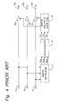
- Fig. 4 is a block diagram of a conventional white balance adjustment apparatus comprising input terminals 1, white detector 2, integrator 3, white balance gain calculator 4, amplifier 5, and output terminals 6.
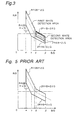
- Fig. 5 is an example showing the white detection area of the white detector 2 in this conventional white balance adjustment apparatus.
- the axis of abscissas is the B/G axis
- the axis of ordinates is the R/G axis
- the dotted line is the axis of color temperature change
- the area contained within the solid line is the white detection area.
- the red (R), green (G), and blue (B) video signals input to input terminals 1a, 1b, and 1c are input to the white detector 2.
- the white detector 2 passes as output signals Rw, Gw, and Bw only those near-achromatic signal components of the input video signal that are within the white detection area shown in Fig. 5.
- the integrator 3 integrates one field of the near-achromatic video signal output from the white detector 2, and outputs integrated values Rs, Gs, and Bs.
- the white balance gain calculator 4 then calculates the white balance gain from the output signals Rs, Gs, and Bs from the integrator 3, and adjusts the amplification factor of the amplifier 5.
- the white-balanced video signals R', G', and B' are then output from the output terminals 6a, 6b, and 6c.
- the video signals entering the white detection area are not necessarily achromatic, when relatively pale colors near the axis of color temperature change, e.g., white skin tones and greenery outdoors, enter the screen, the conventional apparatus described above falsely determines these color signals to be achromatic, resulting in washed-out colors with white skin tones becoming white.
- an object of the present invention is to provide a white balance adjustment apparatus for suppressing fading due to low saturation chromatic colors.
- a white balance adjustment apparatus for adjusting color component video signals video of an aimed subject is characterized by brightness detecting means detecting the brightness of the subject; and mode selecting means for selecting either one of an outdoor lighting mode and an indoor lighting mode in accordance with the brightness detected by said brightness detecting means; said white detecting means detecting pixels of said color component video signals that falls in a narrow white range when said outdoor lighting mode is selected and in a wide white range when said indoor lighting mode is selected.
- the white balance adjustment apparatus thus sets a white detection area according to the subject brightness information detected by the brightness information detecting means, integrates only the signals entering the set white detection area, and calculates the white balance gain from the integrated values to adjust the amplification factor. It is therefore possible to restrict the white detection area to the outdoor light distribution area when operating under bright outdoor lighting, thereby preventing the false evaluation of chromatic signals as achromatic signals even when relatively light colors near the axis of color temperature change, such as white skin tones and outdoor greenery, enter the screen.
- the object of this embodiment is to use brightness information to determine whether the subject being recorded is exposed under a strong light, such as outdoor light, or under weak light, such as indoor light, and to prevent color fading and similar operating errors by restricting the color temperature detection frame when operating under strong light as in outdoor light.
- a strong light such as outdoor light
- weak light such as indoor light
- Fig. 1. is a block diagram of a white balance adjustment apparatus according to the embodiment of the invention.
- the white balance adjustment apparatus comprises input terminals 1a, 1b, 1c, a white detector 2, an integrator 3, a white balance gain calculator 4, amplifiers 5a, 5b, 5c, output terminals 6a, 6b, 6c, brightness detector 7, and mode selector 8.
- the mode selector 8 comprises a comparator which determines whether the subject being currently recorded is illuminated by strong light (outdoor light) or weak light (indoor light) based on the output signal from the brightness detector 7, and outputs a HIGH signal if the primary light source is determined to be strong light (outdoor light); it otherwise outputs a LOW signal.
- the brightness detector 7 used here may be the adjustor for the iris mechanism that adjusts the exposure of the imaging device.
- the comparator in the mode selector 8 compares the iris adjustment signal with a predetermined threshold level Thf, and determines the primary light source to be strong outdoor light when the iris is closed beyond a certain level, that is when the iris adjustment signal is greater than the threshold level Thf, and thus produces a HIGH signal.
- Fig. 2 also shows a block diagram of the white detector 2 in a white balance adjustment apparatus according to the embodiment of the present invention.
- the white detector 2 comprises amplifiers 9a, 9b, 9c, 9d, 9e, 9f, 9g, 9h, 9i, 9j, comparators 10a, 10a, 10c, 10d, 10e, 10f, 10g, 10h, adders 11a, 11b, AND circuits 12a, 12b, 12c, an OR circuit 13, and multiplexers 14a, 14b.
- the B signal input to input terminal ld of the white detector 2 is input to comparators 10a, 10b, and 10g.
- the B signal input to input terminal 1d is also doubled by amplifier 9a and added to the R signal by adder 11a, and the sum signal (R + 2B) is input to comparators 10c and 10d.
- the R signal input to input terminal 1e is doubled by amplifier 9b and added to the B signal by adder 11b, and the sum signal (2R + B) is input to comparators 10e, 10f, and 10h.
- the G signal input to input terminal 1f is multiplied ⁇ , ⁇ , ⁇ , ⁇ , ⁇ , ⁇ and times, respectively, by amplifiers 9c, 9d, 9e, 9f, 9g, 9h, 9i and 9j, and the resulting products are input to comparators 10a, 10b, 10g, 10c, 10d, 10e, 10f, and 10h, respectively.
- Comparator 10a compares the B signal with the ⁇ -times multiplied G signal, and outputs a HIGH signal if the B signal is greater.
- Comparator 10b compares the B signal with the ⁇ -times multiplied G signal, and outputs a HIGH signal if the ⁇ -times multiplied G signal is greater.
- Comparator 10c compares the (R + 2B) signal with the ⁇ -times multiplied G signal, and outputs a HIGH signal if the (R + 2B) signal is greater.
- Comparator 10d compares the (R + 2B) signal with the ⁇ -times multiplied G signal, and outputs a HIGH signal if the ⁇ -times multiplied G signal is greater.
- Comparator 10e compares the (2R + B) signal with the ⁇ -times multiplied G signal, and outputs a HIGH signal if the (2R + B) signal is greater.
- Comparator 10f compares the (2R + B) signal with the ⁇ -times multiplied G signal, and outputs a HIGH signal if the ⁇ -times multiplied G signal is greater.
- Comparator 10g compares the B signal with the ⁇ -times multiplied G signal, and outputs a HIGH signal if the B signal is greater.
- Comparator 10h compares the (2R + B) signal with the -times multiplied G signal, and outputs a HIGH signal if the (2R + B) signal is greater.
- AND circuit 12a outputs a HIGH signal when the outputs from comparators 10a, 10c, 10d, and 10e are all HIGH.
- AND circuit 12b outputs a HIGH signal when the outputs from comparators 10b, 10e, 10f, and 10g are all HIGH.
- AND circuit 12c outputs a HIGH signal when the outputs from comparators 10b, 10f, 10g, and 10h are all HIGH.
- the OR circuit 13 outputs a HIGH signal when the output from either AND circuit 12a or AND circuit 12b is HIGH. As a result, the OR circuit 13 outputs a HIGH signal when the condition defined by equation 1 below is satisfied. ⁇ G ⁇ B ⁇ ⁇ G AND ⁇ G ⁇ (R + 2B) ⁇ ⁇ G AND 2 ⁇ G ⁇ (2R + B) ⁇ or ⁇ G ⁇ B ⁇ ⁇ G AND 2 ⁇ G ⁇ (2R + B) ⁇ 2 ⁇ G ⁇
- the AND circuit 12c outputs a HIGH signal when the condition defined by equation 2 below is satisfied.
- Fig. 3 The signal area or region satisfying these conditions is simulated in Fig. 3.
- the axis of abscissas is (B/G)
- the axis of ordinates is (R/G)
- the dashed line in the shape of " ⁇ " is the axis of change in the color temperature of the light source.
- the wide region in which the OR circuit 13 outputs HIGH is the " ⁇ " shaped region defined by the solid line and indicated as a "first white detection area”
- the narrow region in which the AND circuit 12c outputs HIGH is the shaded area which is indicated as a "second white detection area”.
- the gain of amplifiers 9c - 9j is adjusted so that this " ⁇ " shaped wide region covers the spectrum of both outdoor light and artificial light ranging in color temperature from, for example, 3000-K halogen lamps to 10,000-K outdoor light, and the shaded narrow region covers the spectrum of only outdoor light ranging in color temperature from, for example, 4500-K to 10,000-K.
- a point is plotted in the graph of Fig. 3 in response to every pixel video data.
- the OR circuit 13 produces a HIGH signal when the plotted point falls within the first wide white detection area
- the AND circuit 12c produces a HIGH signal when the plotted point falls within the second narrow white detection area. Since the second narrow white detection area is completely contained in the first wide white detection area, the plotted point that falls in the second narrow white detection area always falls in the first wide white detection area.
- the first wide white detection area is defined as an area in which the pixel color can be considered as white under indoor (weak) lighting.
- the second narrow white detection area is defined as an area in which the pixel color can be considered as white under outdoor (strong) lighting.
- the output signals from the OR circuit 13 and AND circuit 12c are input to multiplexer 14a.
- multiplexer 14a selects the output signal from the OR circuit 13, as shown by the real line; and when the white detection area setting signal is HIGH, representing the outdoor strong lighting, multiplexer 14a selects the output signal from the AND circuit 12c, as shown by the dotted line.
- the B, R, and G signals input to the input terminals 1d, 1e, and 1f of the white detector 2, respectively, are also input to the second multiplexer 14b.
- the second multiplexer 14b When the output from the first multiplexer 14a is HIGH, the second multiplexer 14b is turned to a position shown by the real line, so that the video signals are selected and applied to terminals 6d, 6e and 6f; when the output of multiplexer 14a is LOW, the second multiplexer 14b is turned to a position shown by the dotted line, so that "0" (the ground level) is output.
- the output signals from the multiplexer 14b are thus output from output terminals 6d, 6e, and 6f as the achromatic video signals Bw, Rw, and Gw from the white detector 2.
- the Bw, Rw, and Gw output signals from the white detector 2 are then input to the integrator 3 for integrating each of the achromatic video signals Bw, Rw, and Gw.
- the integrator for integrating the achromatic video signal Bw includes an adder and a delay.
- the adder adds the data cumulated in the delay.
- the delay is reset at the end of each field.
- the delay cumulates the achromatic video signal Bw from all the pixels that are detected as the white point pixels.
- the delay produces an integrated signal Bs.
- the integrators for integrating the achromatic video signals Rw and Gw have the same structure as the integrator for integrating the achromatic video signal Bw. Thus, after every field, integrated signals Rs, Gs, and Bs are output.
- a counter can be used for cumulating the detected signal.
- the output signals Rs, Gs and Bs from the integrator 3 are input to the white balance gain calculator 4, which is defined by two dividers.
- the first divider divides the signal Gs by the signal Bs to produce a quotient signal Gs/Bs.
- the second divider divides the signal Gs by the signal Rs to produce a quotient signal Gs/Rs.
- the quotient signal Gs/Rs is applied to amplifier 5a which then produces a product signal R ⁇ (Gs/Rs).
- the quotient signal Gs/Bs is applied to amplifier 5c which then produces a product signal B ⁇ (Gs/Bs). In this manner, the white-balanced signals are output from output terminals 6a, 6b, and 6c.
- the second narrow white detection area is not provided as in the prior art, the spectral distribution of light yellow, light green, white skin-toned subjects under outdoor light will fall within the first wide white detection area, so that the light yellow, light green and white skin-toned subjects are forcibly made white or whitish in the reproduced image.
- the white balance gain control is done with respect to purer white colors, resulting in a high accuracy white balance.
- the white balance gain calculation is done for the whitish subjects that falls within the first white detection area for both indoor lights and outdoor lights.
- the light yellow, light green and white skin-toned subjects are all used for the basis of the white balance gain calculation.
- the white balance gain calculation is done with more whitish subject that falls in the second white detection area, so that white and other colors can be expressed with higher precision.
- the effect of the present invention thus described is to determine from the brightness information whether the primary light source is indoor weak light or outdoor strong light, and restrict the range of the white detection area when the primary light source is outdoor light.
- the effects of chromatic colors in the indoor light spectrum e.g., yellows, green, and white skin tones, when exposed to outdoor light can be avoided to enable accurate white detection, and high precision white balancing can be obtained.
- RGB primary color signal has been used by way of example in the description of the embodiment above, the same effects can be obtained using Y, R-Y, and B-y luminance and color difference signals by slightly modifying the configuration of the mode selector and the color temperature detector.
- the embodiment above applies a feed-forward type color temperature detection method using the signal before white balance adjustment, but the same effects can be obtained applying a feedback-type method using the signals after white balancing by slightly modifying the configuration of the mode selector and the color temperature detector.
- the video signal is used for color temperature detection in the embodiment above, but the same effects can be obtained by dividing each field into plural blocks and using the color signal representative of each block.
- red (R), green (G), and blue (B) video signals are used, but other color component signals, such as R-Y, B-Y and Y signals or magenta, green, cyan, and yellow signals can be used.
- magenta, green, cyan, and yellow signals are used, the color temperature information Cbs and Crs will be used for the amplification factors of the amplifiers for the magenta+yellow and the magenta+cyan.
- the invention thus described, it is possible to restrict the white detection area when exposed to particularly bright outdoor light by setting the white detection area according to the brightness information of the subject detected by a brightness detector, integrating only the signals within the set white detection area, calculating the white balance gain from the integrated values, and adjusting the amplification factor by the calculated white balance gain.
- relatively light colors such as white skin tones and green outdoors, near the axis of color temperature change are in the field, the color signals therefrom will not be falsely detected as achromatic, and related operating errors, such as fading causing white skin tones to appear washed out, can be effectively prevented.
Claims (1)
- Dispositif d'ajustement de l'équilibre du blanc destiné à ajuster des signaux vidéo de composantes de couleur d'un sujet visé, comprenant :caractérisé par un moyen de détection de luminosité (7) détectant la luminosité du sujet, etun moyen d'amplification (5a, 5b, 5c) destiné à amplifier lesdits signaux vidéo de composantes de couleur (R, V, B) de façon séparée,un moyen de détection du blanc (2) recevant lesdits signaux vidéo de composantes de couleur (R, V, B) pour chaque pixel,un moyen de cumul (3) destiné à cumuler le nombre de pixels détectés, etun moyen de calcul de gain d'équilibre du blanc (4) destiné à commander le gain dudit moyen d'amplification (5a, 5c) sur la base du résultat cumulé dudit moyen de cumul (3),un moyen de sélection de mode (8) destiné à sélectionner l'un ou l'autre d'un mode d'éclairage naturel et d'un mode d'éclairage artificiel conformément à la luminosité détectée par le moyen de détection de luminosité (7),ledit moyen de détection du blanc (2) détectant des pixels desdits signaux vidéo de composantes de couleur qui tombent dans une plage de blanc étroite lorsque ledit mode d'éclairage naturel est sélectionné, et dans une plage de blanc large lorsque ledit mode d'éclairage artificiel est sélectionné.
Applications Claiming Priority (3)
| Application Number | Priority Date | Filing Date | Title |
|---|---|---|---|
| JP30793693 | 1993-12-08 | ||
| JP5307936A JPH07162890A (ja) | 1993-12-08 | 1993-12-08 | ホワイトバランス調整装置 |
| JP307936/93 | 1993-12-08 |
Publications (3)
| Publication Number | Publication Date |
|---|---|
| EP0658058A2 EP0658058A2 (fr) | 1995-06-14 |
| EP0658058A3 EP0658058A3 (fr) | 1998-12-23 |
| EP0658058B1 true EP0658058B1 (fr) | 2001-03-14 |
Family
ID=17974962
Family Applications (1)
| Application Number | Title | Priority Date | Filing Date |
|---|---|---|---|
| EP94119186A Expired - Lifetime EP0658058B1 (fr) | 1993-12-08 | 1994-12-06 | Appareil d'ajustement de l'équilibre du blanc |
Country Status (4)
| Country | Link |
|---|---|
| US (2) | US5481302A (fr) |
| EP (1) | EP0658058B1 (fr) |
| JP (1) | JPH07162890A (fr) |
| DE (1) | DE69426861T2 (fr) |
Families Citing this family (66)
| Publication number | Priority date | Publication date | Assignee | Title |
|---|---|---|---|---|
| US6016161A (en) * | 1996-01-25 | 2000-01-18 | Medar, Inc. | Method and system for automatically calibrating a color-based machine vision system |
| US5821993A (en) * | 1996-01-25 | 1998-10-13 | Medar, Inc. | Method and system for automatically calibrating a color camera in a machine vision system |
| JPH10116050A (ja) * | 1996-10-14 | 1998-05-06 | Sony Corp | 輪郭補正回路およびrgbモニタ |
| KR19980052323A (ko) * | 1996-12-24 | 1998-09-25 | 구자홍 | 온도센서를 이용한 자동 색온도 조정장치 |
| JP3153147B2 (ja) * | 1997-03-14 | 2001-04-03 | 松下電器産業株式会社 | 撮像装置 |
| JPH11168750A (ja) * | 1997-09-30 | 1999-06-22 | Ricoh Co Ltd | デジタルカメラ調整装置 |
| JP4212134B2 (ja) * | 1997-12-25 | 2009-01-21 | 三洋電機株式会社 | 画像信号処理装置 |
| US6069972A (en) * | 1998-06-02 | 2000-05-30 | Intel Corporation | Global white point detection and white balance for color images |
| JP3847965B2 (ja) * | 1998-07-30 | 2006-11-22 | キヤノン株式会社 | 撮像装置 |
| US6067399A (en) * | 1998-09-02 | 2000-05-23 | Sony Corporation | Privacy mode for acquisition cameras and camcorders |
| JP3849834B2 (ja) * | 1999-02-02 | 2006-11-22 | 富士写真フイルム株式会社 | オートホワイトバランス制御方法 |
| JP3540679B2 (ja) | 1999-08-31 | 2004-07-07 | 三洋電機株式会社 | 白バランス調整回路 |
| US6906744B1 (en) * | 1999-09-28 | 2005-06-14 | Nikon Corporation | Electronic camera |
| US6770861B2 (en) * | 2000-03-08 | 2004-08-03 | Minolta Co., Ltd. | Image-sensing device |
| JP3892648B2 (ja) * | 2000-06-30 | 2007-03-14 | 株式会社リコー | 画像入力装置、ホワイトバランス調整方法、およびその方法を実行するためのプログラムを格納したコンピュータが読取可能な記録媒体 |
| JP4543514B2 (ja) * | 2000-07-18 | 2010-09-15 | 株式会社ニコン | 電子カメラ |
| JP4288553B2 (ja) * | 2000-07-25 | 2009-07-01 | 富士フイルム株式会社 | カメラのストロボ装置 |
| JP2002152772A (ja) * | 2000-08-28 | 2002-05-24 | Fuji Photo Film Co Ltd | ホワイトバランス補正装置及びホワイトバランス補正方法と濃度補正方法並びにこれらの方法を実行するためのプログラムを記録した記録媒体 |
| FR2817986B1 (fr) * | 2000-12-07 | 2003-03-28 | Lyon Ecole Centrale | Procede de classification d'une image en couleur selon la prise de vue en exterieur ou en interieur |
| AU2002233292A1 (en) | 2000-12-21 | 2002-07-01 | 3M Innovative Properties Company | Grounding plate and telecommunications module including a grounding plate and telecommunications rack-mounting system including a module |
| JP2003102022A (ja) * | 2001-09-21 | 2003-04-04 | Canon Inc | 撮像装置及び撮像方法 |
| EP1311111A3 (fr) * | 2001-11-08 | 2004-12-08 | Fuji Photo Film Co., Ltd. | Procédé et appareil pour la correction de l'équilibre du blanc, procédé pour la correction de la densité et support d'enregistrement de programme |
| JP3821729B2 (ja) * | 2002-03-07 | 2006-09-13 | 富士写真フイルム株式会社 | デジタルカメラ |
| US6573932B1 (en) * | 2002-03-15 | 2003-06-03 | Eastman Kodak Company | Method for automatic white balance of digital images |
| US6995791B2 (en) * | 2002-04-02 | 2006-02-07 | Freescale Semiconductor, Inc. | Automatic white balance for digital imaging |
| US7158174B2 (en) * | 2002-04-04 | 2007-01-02 | Eastman Kodak Company | Method for automatic white balance of digital images |
| US6888553B2 (en) * | 2002-05-10 | 2005-05-03 | Samsung Electronics Co., Ltd. | Apparatus and method for adjusting color temperature of displayed image using color temperature metadata |
| US7295213B2 (en) * | 2002-05-10 | 2007-11-13 | Samsung Electronics Co., Ltd. | Apparatus and method for converting metadata color temperature and apparatus and method for providing metadata |
| JP2003348601A (ja) * | 2002-05-27 | 2003-12-05 | Fuji Photo Film Co Ltd | オートホワイトバランス制御方法及び電子カメラ |
| US7162078B2 (en) * | 2002-12-20 | 2007-01-09 | Fast Link Communication Corp. | Automatic white balance correction method for image capturing apparatus |
| US7684096B2 (en) * | 2003-04-01 | 2010-03-23 | Avid Technology, Inc. | Automatic color correction for sequences of images |
| JP4158592B2 (ja) * | 2003-04-25 | 2008-10-01 | 富士フイルム株式会社 | オートホワイトバランス調整方法及びこの方法が適用されたカメラ |
| JP4269780B2 (ja) * | 2003-05-26 | 2009-05-27 | 株式会社ニコン | 画像処理装置、電子カメラ、及び画像処理プログラム |
| JP2005027033A (ja) * | 2003-07-02 | 2005-01-27 | Nikon Corp | カラー撮像装置 |
| US7545412B2 (en) * | 2003-09-09 | 2009-06-09 | Konica Minolta Holdings, Inc. | Image-sensing apparatus with a solid-state image sensor switchable between linear and logarithmic conversion |
| DE10349254A1 (de) * | 2003-10-20 | 2005-05-12 | Transmit Technologietransfer | Intraokulare Linseneinrichtung zur Verbesserung des Sehvermögens bei Netzhauterkrankungen |
| JPWO2005041588A1 (ja) * | 2003-10-24 | 2007-04-05 | ノキア コーポレイション | 色味補正機能を有する撮影機能を備えた電子機器、及び、画像データの色味補正方法 |
| JP4041995B2 (ja) * | 2004-06-22 | 2008-02-06 | ソニー株式会社 | 撮像装置及び撮像方法 |
| US7728880B2 (en) | 2004-06-25 | 2010-06-01 | Qualcomm Incorporated | Automatic white balance method and apparatus |
| KR20060004023A (ko) * | 2004-07-08 | 2006-01-12 | 삼성전자주식회사 | 야외 및 실내 환경에 적합한 색감을 표현해주는정지화상의 촬영방법 및 이를 수행하기 위한 촬영장치 |
| KR20060006138A (ko) * | 2004-07-15 | 2006-01-19 | 삼성전자주식회사 | 컬러 신호의 이득 레벨을 조절하기 위한 제어신호 생성방법 및 제어신호 생성 장치 |
| JP2006173659A (ja) * | 2004-12-10 | 2006-06-29 | Sony Corp | 画像処理装置、画像処理方法及び撮像装置 |
| WO2006067724A2 (fr) * | 2004-12-22 | 2006-06-29 | Koninklijke Philips Electronics N.V. | Commande d'equilibrage automatique des blancs |
| JP4960597B2 (ja) * | 2005-02-22 | 2012-06-27 | キヤノン株式会社 | ホワイトバランス補正装置及び方法、及び撮像装置 |
| KR100566564B1 (ko) * | 2005-04-25 | 2006-03-31 | 엠텍비젼 주식회사 | 색 온도 검출 방법 및 장치 |
| JP4670465B2 (ja) * | 2005-05-11 | 2011-04-13 | ソニー株式会社 | ホワイトバランス制御装置 |
| JP4434073B2 (ja) * | 2005-05-16 | 2010-03-17 | ソニー株式会社 | 画像処理装置および撮像装置 |
| US20070027651A1 (en) * | 2005-07-27 | 2007-02-01 | Ng Joh J | System and method for a color sensor |
| US8064110B2 (en) | 2005-12-08 | 2011-11-22 | Qualcomm Incorporated | Adaptive auto white balance |
| JP2008153768A (ja) * | 2006-12-14 | 2008-07-03 | Eastman Kodak Co | 撮像装置、およびホワイトバランス処理装置 |
| US7974487B2 (en) * | 2007-04-17 | 2011-07-05 | Kabushiki Kaisha Toshiba | System and method for image white balance adjustment |
| JP5091550B2 (ja) * | 2007-06-12 | 2012-12-05 | 株式会社エルモ社 | ホワイトバランス調整装置およびホワイトバランス調整方法 |
| KR100925629B1 (ko) * | 2007-12-07 | 2009-11-06 | 삼성전기주식회사 | YCbCr 색공간에서의 오토 화이트 밸런스 방법 |
| KR101451982B1 (ko) * | 2008-02-12 | 2014-10-24 | 삼성전자주식회사 | 디지털 영상 장치에서 화이트 밸런스 조정 장치 및 방법 |
| JP5175680B2 (ja) * | 2008-02-15 | 2013-04-03 | パナソニック株式会社 | 撮像装置、波形信号表示方法、プログラムおよび集積回路 |
| KR20090120991A (ko) * | 2008-05-21 | 2009-11-25 | 엘지이노텍 주식회사 | 자동 화이트 밸런스 영역 설정 방법 |
| KR20100066855A (ko) * | 2008-12-10 | 2010-06-18 | 삼성전자주식회사 | 촬상 장치 및 촬상 방법 |
| JP4867983B2 (ja) * | 2008-12-11 | 2012-02-01 | セイコーエプソン株式会社 | 画像信号処理装置及びその方法 |
| JP5321163B2 (ja) * | 2009-03-12 | 2013-10-23 | 株式会社リコー | 撮像装置及び撮像方法 |
| JP5821214B2 (ja) * | 2011-02-28 | 2015-11-24 | ソニー株式会社 | 画像処理装置と画像処理方法およびプログラム |
| US8440772B2 (en) | 2011-04-28 | 2013-05-14 | Chevron Phillips Chemical Company Lp | Methods for terminating olefin polymerizations |
| DE102012007982A1 (de) * | 2012-04-20 | 2013-10-24 | Connaught Electronics Ltd. | Verfahren zum Weißabgleich eines Bildes unter Berücksichtigung der Farbgebung des Kraftfahrzeugs |
| US10273315B2 (en) | 2012-06-20 | 2019-04-30 | Chevron Phillips Chemical Company Lp | Methods for terminating olefin polymerizations |
| KR102198852B1 (ko) * | 2014-03-24 | 2021-01-05 | 삼성전자 주식회사 | 홍채 인식 장치 및 이를 포함하는 모바일 장치 |
| CN111225469A (zh) * | 2019-12-06 | 2020-06-02 | 长春希达电子技术有限公司 | 防止不同色温下白场漂移的led照明灯具亮度补偿方法 |
| CN113691793B (zh) * | 2020-05-19 | 2024-01-05 | 瑞昱半导体股份有限公司 | 图像白平衡处理方法 |
Family Cites Families (21)
| Publication number | Priority date | Publication date | Assignee | Title |
|---|---|---|---|---|
| JPH0693781B2 (ja) * | 1985-02-08 | 1994-11-16 | 株式会社東芝 | 自動白バランス制御回路 |
| JP2594913B2 (ja) * | 1985-12-04 | 1997-03-26 | 株式会社日立製作所 | カラービデオカメラ |
| JPH075733Y2 (ja) * | 1986-09-08 | 1995-02-08 | 日本ビクター株式会社 | カラ−テレビジヨンカメラの白バランス回路 |
| JPH0817497B2 (ja) * | 1987-08-27 | 1996-02-21 | キヤノン株式会社 | 自動ホワイト・バランス補正装置 |
| JP2860545B2 (ja) * | 1987-08-27 | 1999-02-24 | キヤノン株式会社 | 自動ホワイト・バランス補正装置 |
| JP2531961B2 (ja) * | 1987-08-27 | 1996-09-04 | キヤノン株式会社 | 自動ホワイト・バランス補正装置 |
| US5264921A (en) * | 1987-11-30 | 1993-11-23 | Canon Kabushiki Kaisha | White balance including means for preventing colored object from disturbing the balance |
| JP2508951Y2 (ja) * | 1988-02-03 | 1996-08-28 | 富士写真フイルム株式会社 | 白バランス調節装置 |
| JPH0817499B2 (ja) * | 1988-04-20 | 1996-02-21 | 富士写真フイルム株式会社 | カメラの白バランス調整装置 |
| US5045928A (en) * | 1988-04-21 | 1991-09-03 | Canon Kabushiki Kaisha | White balance control with choice of control dependent on brightness |
| JP2696937B2 (ja) * | 1988-06-20 | 1998-01-14 | ソニー株式会社 | 撮像装置 |
| US5270802A (en) * | 1989-04-14 | 1993-12-14 | Hitachi, Ltd. | White balance adjusting device for video camera |
| JPH02272892A (ja) * | 1989-04-14 | 1990-11-07 | Hitachi Ltd | ホワイトバランス制御装置 |
| JPH033497A (ja) * | 1989-05-31 | 1991-01-09 | Hitachi Ltd | ビデオカメラの信号処理方式 |
| US5442408A (en) * | 1989-11-17 | 1995-08-15 | Sanyo Electric Co., Ltd. | White balance adjusting apparatus for automatically adjusting white balance in response to luminance information signal and color information signal obtained from image sensing device |
| JP3034542B2 (ja) * | 1990-01-17 | 2000-04-17 | 株式会社日立製作所 | ホワイトバランス制御装置 |
| JP2532965B2 (ja) * | 1990-04-18 | 1996-09-11 | 三洋電機株式会社 | カラ―ビデオカメラ |
| JP2523040B2 (ja) * | 1990-04-18 | 1996-08-07 | 三洋電機株式会社 | カラ―ビデオカメラ |
| US5177599A (en) * | 1990-07-23 | 1993-01-05 | Hitachi, Ltd. | White balance controller for an image pick-up apparatus including an abnormality detector |
| US5361093A (en) * | 1991-09-02 | 1994-11-01 | Matsushita Electric Industrial Co., Ltd. | Automatic white balance setting device |
| DE69227869T2 (de) * | 1991-09-05 | 1999-06-02 | Canon Kk | Weissabgleichssteuerung für eine Bildaufnahmevorrichtung |
-
1993
- 1993-12-08 JP JP5307936A patent/JPH07162890A/ja active Pending
-
1994
- 1994-12-06 EP EP94119186A patent/EP0658058B1/fr not_active Expired - Lifetime
- 1994-12-06 US US08/349,955 patent/US5481302A/en not_active Expired - Fee Related
- 1994-12-06 DE DE69426861T patent/DE69426861T2/de not_active Expired - Fee Related
-
1995
- 1995-09-18 US US08/529,686 patent/US5541649A/en not_active Expired - Lifetime
Also Published As
| Publication number | Publication date |
|---|---|
| US5541649A (en) | 1996-07-30 |
| EP0658058A2 (fr) | 1995-06-14 |
| DE69426861T2 (de) | 2001-06-21 |
| EP0658058A3 (fr) | 1998-12-23 |
| JPH07162890A (ja) | 1995-06-23 |
| US5481302A (en) | 1996-01-02 |
| DE69426861D1 (de) | 2001-04-19 |
Similar Documents
| Publication | Publication Date | Title |
|---|---|---|
| EP0658058B1 (fr) | Appareil d'ajustement de l'équilibre du blanc | |
| KR900004034B1 (ko) | 칼라 비디오 카메라의 화이트 바란스 조정장치 | |
| US5282022A (en) | White balance adjusting apparatus for automatically adjusting white balance in response to luminance information signal and color information signal obtained from image sensing device | |
| KR100199322B1 (ko) | 촬상 소자에서 얻어지는 색정보 신호에 기초하여 백색 밸런스 조정을 자동적으로 행하는 백색 밸런스 조정 장치 | |
| US5289268A (en) | Apparatus using brightness information from a photometering circuit and a brightness-converted green component from a color metering circuit to ultimately adjust white balance | |
| EP2426928B1 (fr) | Appareil de traitement d'images, procédé de traitement d'images et programme | |
| EP2426927B1 (fr) | Appareil de traitement d'images, procédé de traitement d'images et programme informatique | |
| US5361093A (en) | Automatic white balance setting device | |
| KR100478064B1 (ko) | 백색 밸런스를 얻기 위한 조명광의 색추정 방법 및 촬상장치 | |
| US7148921B2 (en) | White balance adjustment method, image sensing apparatus, program, and storage medium | |
| US5177599A (en) | White balance controller for an image pick-up apparatus including an abnormality detector | |
| JP3848274B2 (ja) | ホワイトバランス調整方法及び撮像装置及びプログラム及び記憶媒体 | |
| KR100720325B1 (ko) | 텔레비젼 카메라 및 이 텔레비젼 카메라의 화이트 밸런스보정 방법 | |
| JPH05292533A (ja) | オートホワイトバランス装置 | |
| US6741285B2 (en) | Apparatus which adjusts exposure on luminance value of photoelectrically converted image pickup screen | |
| US5563656A (en) | Image sensing apparatus with white balance adjustment | |
| JP2002077937A (ja) | ホワイトバランス制御装置及びホワイトバランス制御方法 | |
| KR100207985B1 (ko) | Cie 표색계를 이용한 화이트 밸런스 조정 장치 | |
| KR940002610B1 (ko) | 화이트 밸런스 제어장치 | |
| JPS612487A (ja) | カラ−ビデオカメラの自動白バランス調整方法 | |
| JPH0564221A (ja) | オートホワイトバランス装置 | |
| JPH11205806A (ja) | ホワイトバランス制御装置 | |
| JP4145704B2 (ja) | ホワイトバランス回路 | |
| JP3010373B2 (ja) | 撮像装置 | |
| KR0125304B1 (ko) | 화이트밸런스조정장치 |
Legal Events
| Date | Code | Title | Description |
|---|---|---|---|
| PUAI | Public reference made under article 153(3) epc to a published international application that has entered the european phase |
Free format text: ORIGINAL CODE: 0009012 |
|
| 17P | Request for examination filed |
Effective date: 19941206 |
|
| AK | Designated contracting states |
Kind code of ref document: A2 Designated state(s): DE FR GB NL |
|
| PUAL | Search report despatched |
Free format text: ORIGINAL CODE: 0009013 |
|
| AK | Designated contracting states |
Kind code of ref document: A3 Designated state(s): DE FR GB NL |
|
| 17Q | First examination report despatched |
Effective date: 19990906 |
|
| GRAG | Despatch of communication of intention to grant |
Free format text: ORIGINAL CODE: EPIDOS AGRA |
|
| GRAG | Despatch of communication of intention to grant |
Free format text: ORIGINAL CODE: EPIDOS AGRA |
|
| GRAH | Despatch of communication of intention to grant a patent |
Free format text: ORIGINAL CODE: EPIDOS IGRA |
|
| GRAH | Despatch of communication of intention to grant a patent |
Free format text: ORIGINAL CODE: EPIDOS IGRA |
|
| GRAA | (expected) grant |
Free format text: ORIGINAL CODE: 0009210 |
|
| AK | Designated contracting states |
Kind code of ref document: B1 Designated state(s): DE FR GB NL |
|
| REF | Corresponds to: |
Ref document number: 69426861 Country of ref document: DE Date of ref document: 20010419 |
|
| ET | Fr: translation filed | ||
| REG | Reference to a national code |
Ref country code: GB Ref legal event code: IF02 |
|
| PLBE | No opposition filed within time limit |
Free format text: ORIGINAL CODE: 0009261 |
|
| STAA | Information on the status of an ep patent application or granted ep patent |
Free format text: STATUS: NO OPPOSITION FILED WITHIN TIME LIMIT |
|
| 26N | No opposition filed | ||
| PGFP | Annual fee paid to national office [announced via postgrant information from national office to epo] |
Ref country code: GB Payment date: 20041201 Year of fee payment: 11 |
|
| PGFP | Annual fee paid to national office [announced via postgrant information from national office to epo] |
Ref country code: DE Payment date: 20041202 Year of fee payment: 11 |
|
| PGFP | Annual fee paid to national office [announced via postgrant information from national office to epo] |
Ref country code: NL Payment date: 20041205 Year of fee payment: 11 |
|
| PGFP | Annual fee paid to national office [announced via postgrant information from national office to epo] |
Ref country code: FR Payment date: 20041208 Year of fee payment: 11 |
|
| PG25 | Lapsed in a contracting state [announced via postgrant information from national office to epo] |
Ref country code: GB Free format text: LAPSE BECAUSE OF NON-PAYMENT OF DUE FEES Effective date: 20051206 |
|
| PG25 | Lapsed in a contracting state [announced via postgrant information from national office to epo] |
Ref country code: NL Free format text: LAPSE BECAUSE OF NON-PAYMENT OF DUE FEES Effective date: 20060701 Ref country code: DE Free format text: LAPSE BECAUSE OF NON-PAYMENT OF DUE FEES Effective date: 20060701 |
|
| GBPC | Gb: european patent ceased through non-payment of renewal fee |
Effective date: 20051206 |
|
| PG25 | Lapsed in a contracting state [announced via postgrant information from national office to epo] |
Ref country code: FR Free format text: LAPSE BECAUSE OF NON-PAYMENT OF DUE FEES Effective date: 20060831 |
|
| NLV4 | Nl: lapsed or anulled due to non-payment of the annual fee |
Effective date: 20060701 |
|
| REG | Reference to a national code |
Ref country code: FR Ref legal event code: ST Effective date: 20060831 |