EP0657221B1 - Zentrifugenrotor-Haltevorrichtung - Google Patents
Zentrifugenrotor-Haltevorrichtung Download PDFInfo
- Publication number
- EP0657221B1 EP0657221B1 EP94309212A EP94309212A EP0657221B1 EP 0657221 B1 EP0657221 B1 EP 0657221B1 EP 94309212 A EP94309212 A EP 94309212A EP 94309212 A EP94309212 A EP 94309212A EP 0657221 B1 EP0657221 B1 EP 0657221B1
- Authority
- EP
- European Patent Office
- Prior art keywords
- stem
- jaw
- retaining arm
- moveable
- moveable jaw
- Prior art date
- Legal status (The legal status is an assumption and is not a legal conclusion. Google has not performed a legal analysis and makes no representation as to the accuracy of the status listed.)
- Expired - Lifetime
Links
- 239000008280 blood Substances 0.000 claims description 5
- 210000004369 blood Anatomy 0.000 claims description 5
- 230000033001 locomotion Effects 0.000 claims description 3
- 230000013011 mating Effects 0.000 claims 1
- 230000006835 compression Effects 0.000 description 4
- 238000007906 compression Methods 0.000 description 4
- 238000000034 method Methods 0.000 description 4
- 239000000306 component Substances 0.000 description 3
- 239000012530 fluid Substances 0.000 description 2
- 238000000926 separation method Methods 0.000 description 2
- 229910000906 Bronze Inorganic materials 0.000 description 1
- 230000000903 blocking effect Effects 0.000 description 1
- 239000012503 blood component Substances 0.000 description 1
- 239000010974 bronze Substances 0.000 description 1
- 238000004891 communication Methods 0.000 description 1
- 239000000470 constituent Substances 0.000 description 1
- 239000000356 contaminant Substances 0.000 description 1
- KUNSUQLRTQLHQQ-UHFFFAOYSA-N copper tin Chemical compound [Cu].[Sn] KUNSUQLRTQLHQQ-UHFFFAOYSA-N 0.000 description 1
- 230000000881 depressing effect Effects 0.000 description 1
- 230000000694 effects Effects 0.000 description 1
- 239000000463 material Substances 0.000 description 1
- 239000002184 metal Substances 0.000 description 1
- 229910052751 metal Inorganic materials 0.000 description 1
- 150000002739 metals Chemical class 0.000 description 1
- 229920003023 plastic Polymers 0.000 description 1
- 239000004033 plastic Substances 0.000 description 1
- 229920000642 polymer Polymers 0.000 description 1
- 230000011664 signaling Effects 0.000 description 1
- 229910001220 stainless steel Inorganic materials 0.000 description 1
- 239000010935 stainless steel Substances 0.000 description 1
Images


Classifications
-
- B—PERFORMING OPERATIONS; TRANSPORTING
- B04—CENTRIFUGAL APPARATUS OR MACHINES FOR CARRYING-OUT PHYSICAL OR CHEMICAL PROCESSES
- B04B—CENTRIFUGES
- B04B7/00—Elements of centrifuges
-
- B—PERFORMING OPERATIONS; TRANSPORTING
- B04—CENTRIFUGAL APPARATUS OR MACHINES FOR CARRYING-OUT PHYSICAL OR CHEMICAL PROCESSES
- B04B—CENTRIFUGES
- B04B5/00—Other centrifuges
- B04B5/04—Radial chamber apparatus for separating predominantly liquid mixtures, e.g. butyrometers
- B04B5/0442—Radial chamber apparatus for separating predominantly liquid mixtures, e.g. butyrometers with means for adding or withdrawing liquid substances during the centrifugation, e.g. continuous centrifugation
- B04B2005/0464—Radial chamber apparatus for separating predominantly liquid mixtures, e.g. butyrometers with means for adding or withdrawing liquid substances during the centrifugation, e.g. continuous centrifugation with hollow or massive core in centrifuge bowl
-
- B—PERFORMING OPERATIONS; TRANSPORTING
- B04—CENTRIFUGAL APPARATUS OR MACHINES FOR CARRYING-OUT PHYSICAL OR CHEMICAL PROCESSES
- B04B—CENTRIFUGES
- B04B7/00—Elements of centrifuges
- B04B2007/005—Retaining arms for gripping the stationary part of a centrifuge bowl or hold the bowl itself
Definitions
- Disposable blood processing centrifuge bowels include a rotary bowl body portion having a separation chamber for separation whole blood into constituent components.
- the rotary bowl body portion is commonly connected to a stem portion with a rotary seal.
- the stem portion includes an inlet port which allows whole blood to enter the centrifuge bowl and an outlet port which allows separated blood components to exit.
- the rotary seal allows the rotary bowl body portion to rotate independently of the stem portion so that the inlet and outlet ports can remain stationary.
- Disposable centrifuge bowls required a chuck mechanism for securing the centrifuge bowl to the rotating mechanism during operation and a gripping mechanism for preventing rotation of the stem portion, for deflecting the rotary seal and for axially aligning the bowl in the chuck mechanism.
- Previous methods of securing centrifuge bowls within centrifuges have been time consuming and cumbersome.
- a common method of retaining the centrifuge bowl is by gripping the centrifuge bowl at a steam portion just below the inlet and outlet ports between two pivoting members.
- a locking device locks the two pivoting members together about the centrifuge bowl. See, for example, U.S. 4,889,524, Figure 2, U.S. 3,581,981, Figure 9 and U.S. 3,317,127, Figure 7.
- DE-A-1,237,360 describes an apparatus for gripping a centrifuge bowl having an arm for gripping the stem of the bowl.
- the arm has a jaw and a slideable lock which can be slid open to allow the stem to enter the jaw. Once the stem is inserted into the jaw, the lock is slid into place, trapping the stem between itself and the jaw.
- a drawback of gripping a centrifuge bowl with two pivoting members is that a number of steps must be performed in order to secure the centrifuge bowl.
- Each pivoting member must be independently swung into position about the centrifuge bowl while depressing the header of the centrifuge bowl and then locked in place with the blocking device. This adds to the time required to perform a blood processing operation.
- an apparatus for gripping a centrifuge bowl having a stem and a flange of predetermined shape comprising:
- the retaining arm is moved into a position such that the stationary jaw engages the flange and stem when the bowl is properly secured in the chuck.
- the moveable jaw which is moveably secured to the retaining arm locks the stem of the centrifuge bowl against the stationary jaw.
- the retaining arm is supported by and pivots upon a support block about a first axis which allows the centrifuge bowl to be loaded and unloaded when the retaining arm is rotated out of the way.
- a latching mechanism opens and closes the moveable jaw into and out of gripping position.
- the moveable jaw pivots about a second axis located on the retaining arm.
- a first spring is secured to the moveable jaw and a cam block. An actuating member of pin on the handle of the locking mechanism engages the cam block and applies pressure to the moveable jaw via the cam block and spring to actuate movement of the moveable jaw.
- the first spring compensates for variations in size of the gripped portion of the centrifuge bowl.
- a catch affixed to the handle engages a latching shaft affixed to the support block for securing the handle to the latching shaft when the retaining arm is in a closed or gripping position.
- the flange is of polygonal shape and the stationary jaw is configured to provide orientation surfaces which mate with the flange such that the stem can be gripped only when the bowl is in an axially correct operating position.
- the centrifuge bowl includes a rotary seal located below the stem. The rotary seal has a curved upper surface or header which the retaining arm is positioned to engage and deflect downwardly.
- the present invention provides a simple apparatus and method for gripping a centrifuge bowl.
- the gripping apparatus is capable of swinging into position and locking the centrifuge bowl into place with one easy motion of the hand.
- the gripping apparatus also deflects the rotary seal to proper deflection so that the inlet passageways of the seal are opened to admit fluid during operation.
- rotary bowl 12a is held and rotated within cavity 18 of centrifuge 30 by chuck 130.
- Chuck 130 grips bottom portion 12b of centrifuge bowl 12 with "O" ring 132 and is powered by drive shaft 134.
- the portions of centrifuge bowl 12 above rotary bowl 12a extend beyond lip 14 of cavity 18.
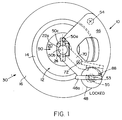
- Stem 22a (located between flange 24 and header 20) is held stationary by gripping apparatus 10 and holds centrifuge bowl 12 in proper axial alignment within cavity 18.
- Gripping apparatus 10 includes a support block 40 for supporting retaining arm 46 which is secured onto surface 44 of housing 16 with screws 42.
- Support block 40 is a curved segment contoured to surround a section of cavity 18.
- Retaining arm 46 is secured to pivot shaft 54 which rotates upon bearing housed within support block 40. Retaining arm 46 deflects header 20 downward to open a passage 6 between skirts 8a and 8b of rotary seal 20a. This connects inlet and outlet ports PT1 and PT2 in fluid communication with rotary bowl 12a.
- a latching mechanism 48 is provided with an integral handle 48a. Handle 48a is rotated to position gripping member 70 into gripping position. Gripping member 70 is pivoted about pivot point 72 and locks stem 22a against surface 50b within stationary jaw 50 of retaining arm 46. Catch 55, affixed to latching mechanism 48, captures latching shaft 53 to secure latching mechanism 48 to support block 40.
- retaining arm 46 is swung out of gripping position in order to load centrifuge bowl 12 into centrifuge apparatus 30.
- Retaining arm 46 is substantially triangular in shape with one side of the triangle being an arc.
- Pivot shaft 54, latching mechanism 48 and jaw 50 are located in respective corners of retaining arm 46.
- retaining arm 46 is swung into gripping position.
- the curved surface of header 20 acts as a ramp for retaining arm 46 as retaining arm 46 moves across the surface of header 20.
- orientation surfaces 51a and 51b engage surfaces 24a and 24b of flange 24, thereby orienting centrifuge bowl 12 in the proper operating axial orientation.
- centrifuge bowl 12 can only be gripped in a proper orientation.
- flange 24 is square.
- flange 24 can be of other suitable polygonal shapes.
- handle 48a of latching mechanism 48 is rotated in a clockwise direction to actuate gripping member 70 such that the curved inner surface of moveable jaw 50c captures stem 22a against stationary jaw surface 50b.
- catch 55 captures latching shaft 53 ( Figure 2) to rigidly lock retaining arm 46 in place.
- Retaining arm 46 has a single cavity 52 formed near the center of the arm to reduce the weight of the arm. Alternatively, multiple cavities 52 can be formed within retaining arm 46 or cavities can be omitted altogether.
- Gripping member 70 is secured to the underside of retaining arm 46 within recessed area 62 by pivot 72.
- a stack of leaf springs 76 are secured to gripping member 70 by bolt 74.
- Leaf springs 76 sandwich cam block 80 against finger 66 of gripping member 70.
- the bottom spring 76a is longer than the other leaf springs and is secured to cam block 80 by screw 78.
- Leaf springs 76 can deflect to provide adjustment for moveable jaw 50c when in a closed position to compensate for any variations in the diameter of stem 22a.
- eight leaf springs 76 are employed to produce ten pounds of force on gripping arm 70.
- the number and stiffness of leaf springs 76 can be varied.
- leaf springs 76 can be substituted for other suitable springs such as torsion springs, extension springs or compression springs.
- Jaw surfaces 50a and 50b are located on the interior of jaw 50. Jaw surface 50a is angled to provide clearance between jaw surface 50a and stem 22a when retaining arm 46 is swung into ripping position. Jaw surface 50b is semicircular or arc shaped to form awaiting surface for capturing stem 22a. Alternatively, jaw surface 50b can be of other suitable shapes such as a vee configuration.
- Actuation pin 88 is affixed to latching mechanism 48 and travels within slot 86 of retaining arm 46. Actuation pin causes gripping member 70 to pivot by engaging curved cam surface 68 of cam block 80, thereby opening and closing moveable jaw 50c. Curved cam surface 68 ramps up to a tip 68a, at which point the moveable jaw 50c is rotated into a closed position. When actuation pin 88 reaches tip 68a, an audible and tactile click is experienced, signaling to the user that the moveable jaw 50c is in a closed position.
- Compression spring 82 is secured to surface 64 by pin 84 and gripping member 70 by hole 70a.
- spring 82 can be replaced with other suitable types of springs.
- handle 48a of latching mechanism 48 is rotated in a counter-clockwise direction whereby pin 88 disengages from tip 68a and travels back down cam surface 68.
- Compression spring 82 applies pressure on gripping member 70 and rotates gripping arm 70 about pivot 72, thereby opening moveable jaw 50c.
- catch 55 rotates to disengage from latching shaft 53.
- Retaining arm 46 can then be swung out of gripping position and centrifuge bowl 12 can be removed from centrifuge apparatus 30.
- Figure 6 depicts a more detailed view of latching mechanism 48 and latching shaft 53.
- Screw 56 rotates relative to retaining arm 46 about bearing B 1 .
- Splash guard 46a protects the components of retaining arm 46 from contaminants.
- bearing B 1 is a roller or ball bearing.
- bearing B 1 can be substituted with other suitable bearing such as needle bearings, bronze bushings or polymer bushings.
- Latching shaft 53 includes a lower shaft portion 53b and an upper shaft portion 53a affixed together by screw 61.
- Neck 59 protrudes from upper shaft portion 53a and mates with a corresponding bar within lower shaft portion 53b. Both neck 59 and the corresponding bore are eccentric with the outer diameters of their respective shaft portions. This allows the horizontal position of upper shaft portion 53a to be adjusted by rotating the upper shaft portion 53a relative to the lower shaft portion 53b.
- Upper shaft portion 53a has a double dovetail configuration which mates with a corresponding female cavity 55a within catch 55.
- the region of catch 55 which captures upper shaft portion 53a is substantially semi-circular ( Figure 5) which allows retaining arm 46 to be swung into gripping position when latching mechanism 48 is in the unlatched position.
- Latching mechanism 48 must be in an unlatched position for retaining arm 46 to be swung into gripping position. If latching mechanism 48 is pivoted into a latched position before retaining arm is attempted to be swung into gripping position, the backside 55b ( Figure 5) of catch 55 will hit latching shaft 53, thereby preventing retaining arm 46 from moving completely into gripping position.
- Threaded stud 57 of lower shaft portion 53b affixes latching shaft 53 to support block 40. Threaded stud 57 also provides vertical adjustment for latching shaft 53 depending upon the depth at which threaded stud 57 is screwed into support block 40.
- FIG. 7 depicts a more detailed view of the manner in which retaining arm pivots relative to support block 40.
- Retaining arm 46 is secured to neck 54a of pivot shaft 54 and rests against shoulder 110.
- Pivot shaft 54 rotates about ball bearings B 2 and B 3 which are housed within sleeve 114 and cavity 116.
- Sleeve 114 rests against shoulder 116a of activity 116 within support block 40.
- Bearings B 2 and B 3 are separated from each other by shoulders 114a.
- Locknut 112 locks pivot shaft 54, bearing B 2 , bearing B 3 and sleeve 114 together.
- a single bearing or bushing can replace bearing B 2 and B 3 .
- the components of gripping apparatus 10 are made of stainless steel. However, other suitable materials such as plastics or other metals can be used. Additionally, although gripping apparatus 10 is shown to be used for gripping bowls of a design similar to that disclosed in U.S. Patent No. 4,983,158, gripping apparatus 10 can be used to grip bowls of other designs, including designs similar to U.S. Patent No. 4,300,717.
Landscapes
- Centrifugal Separators (AREA)
Claims (13)
- Vorrichtung (10) mm Ergreifen eines Zentrifugenkorbs mit einem Stiel (22a) und einem Flansch (24) von bestimmter Gestalt (46), wobei die Vorrichtung die folgenden Merkmale aufweist:einen Haltearm (46) mit einer ortsfesten Backe (50) zum Ergreifen des Stieles (22a); undeine bewegliche Backe (50c); dadurch gekennzeichnet, daß die Vorrichtung weiter die folgenden Merkmale aufweist:Mittel (48) zum schwenkbaren Befestigen der beweglichen Backe am Haltearm, so daß die Schwenkbewegung der beweglichen Backe den Stiel zwischen der ortsfesten und der beweglichen Backe festlegt;eine erste Feder (82), die am Haltearm und an der beweglichen Backe befestigt ist, um die bewegliche Backe vom Stiel wegzudrücken; undeinen Einschnappmechanismus (48), der fest am Haltearm angebracht ist, um die bewegliche Backe in festen Eingriff mit dem Stiel zu halten.
- Vorrichtung nach Anspruch 1, worin der Einschnappmechanismus einen Mitnehmer- bzw. Kurvenblock (80) aufweist, der an der beweglichen Backe mit einer zweiten Feder (76) befestigt ist, die Kraft vom Mitnehmerblock in die bewegliche Backe überträgt.
- Vorrichtung nach Anspruch 2, worin der Einschnappmechanismus ferner die folgenden Merkmale aufweist:einen drehbaren Handgriff (48a); undein Teil (88), das am Handgriff befestigt ist und mit dem Mitnehmerblock so in Verbindung steht, daß die Drehung des Handgriffs den Kurvenblock veranlaßt, sich um einen ersten Schwenkpunkt so zu drehen, daß die bewegliche Backe entgegen der Krafteinwirkung der ersten Feder gedreht wird.
- Vorrichtung nach Anspruch 2 oder 3, worin die zweite Feder so angeordnet ist, daß sie die relativ winklige Bewegung zwischen der beweglichen Backe und Mitnehmerblock ermöglicht, um sich an die Größe des Stieles anzupassen.
- Vorrichtung nach Anspruch 3 oder 4, ferner mit:einem Unterstützungsblock (40) zum Unterstützen des Haltearms;einer Einschnappwelle (53), die am Unterstützungsblock fest angebracht ist; undeinem Fangglied (55), das am Handgriff (48a) angebracht ist, um den Handgriff an der Einschnappwelle fest anzubringen.
- Vorrichtung nach Anspruch 5, worin der Handgriff so ausgebildet ist, daß seine Drehung zur Drehung der beweglichen Backe zum Befestigen des Stiels zwischen der ortsfesten und der beweglichen Backe das Fangglied an der Einschnappwelle befestigt.
- Vorrichtung nach irgendeinem der vorangehenden Ansprüche, worin der Korb einen Außenumfang aufweist, und worin die ortsfeste Backe so ausgebildet ist, daß sie für die Ausrichtung von Flächen sorgt, die zum Flansch an einer vorbestimmten Umfangsausrichtung passen.
- Vorrichtung nach irgendeinem der vorangehenden Ansprüche, worin die ortsfeste Backe eine Innenfläche aufweist, die so geformt ist, daß für eine passende Fläche vorgesehen wird, die zum Stiel paßt.
- Vorrichtung nach irgendeinem der vorangehenden Ansprüche, ferner mit:einem Unterstützungsblock (40); undMitteln (53, 55) zur einer solchen schwenkbaren Befestigung des Haltearmes am Unterstützungsblock, daß der Eingriff der ortsfesten Backe in den Stiel durch Schwenken des Haltearms erleichtert wird.
- Vorrichtung (30) zum Verarbeiten von Blut, mit:einem Zentrifügenkorb (12) mit einem Stiel (22a) und einem Flansch (24) mit vorbestimmter Form; und einer Greifvorrichtung (10) nach irgendeinem der vorangehenden Ansprüche.
- Vorrichtung nach Ansprüch 10, worin der Flansch polygonförmig ist.
- Vorrichtung nach Anspruch 10, worin der Zentrifugenkorb (12) eine rotierende Dichtung (8a, 8b) mit einer gekrümmten oberen Fläche (8a) umfaßt, die unter dem Stiel angeordnet ist, wobei der Haltearm (46) dazu geformt ist, in die obere Fläche der rotierenden Dichtung (8b) einzugreifen und sie nach unten auszulenken, wenn die ortsfeste Backe mit dem Stiel in Eingriff tritt.
- Vorrichtung nach Anspruch 10, ferner mit:einem Spannfütter (130) zum Eingriff in den korbförmigen Teil des Zentrifugenkorbs.
Applications Claiming Priority (2)
| Application Number | Priority Date | Filing Date | Title |
|---|---|---|---|
| US08/165,357 US5505683A (en) | 1993-12-10 | 1993-12-10 | Centrifuge bowl gripping apparatus having a retaining arm with a stationary jaw and a moveable jaw |
| US165357 | 1993-12-10 |
Publications (2)
| Publication Number | Publication Date |
|---|---|
| EP0657221A1 EP0657221A1 (de) | 1995-06-14 |
| EP0657221B1 true EP0657221B1 (de) | 2000-09-06 |
Family
ID=22598565
Family Applications (1)
| Application Number | Title | Priority Date | Filing Date |
|---|---|---|---|
| EP94309212A Expired - Lifetime EP0657221B1 (de) | 1993-12-10 | 1994-12-09 | Zentrifugenrotor-Haltevorrichtung |
Country Status (4)
| Country | Link |
|---|---|
| US (1) | US5505683A (de) |
| EP (1) | EP0657221B1 (de) |
| JP (1) | JPH07308606A (de) |
| DE (1) | DE69425805T2 (de) |
Families Citing this family (25)
| Publication number | Priority date | Publication date | Assignee | Title |
|---|---|---|---|---|
| DK0914212T3 (da) * | 1995-12-07 | 2002-08-12 | Bristol Myers Squibb Co | Centrifugeringsapparat |
| JP3313572B2 (ja) * | 1996-04-03 | 2002-08-12 | ヘモネティクス・コーポレーション | 血液処理用遠心分離器ボウル |
| JP2001508869A (ja) * | 1997-01-08 | 2001-07-03 | ブリストル−マイヤーズ スクイブ カンパニー | 血液を分離するための遠心分離装置 |
| US6979307B2 (en) * | 1997-06-24 | 2005-12-27 | Cascade Medical Enterprises Llc | Systems and methods for preparing autologous fibrin glue |
| US20080199513A1 (en) * | 1997-06-24 | 2008-08-21 | Cascade Medical Enterprises, Llc | Systems and methods for preparing autologous fibrin glue |
| US5924972A (en) * | 1998-03-24 | 1999-07-20 | Turvaville; L. Jackson | Portable D.C. powered centrifuge |
| US6491615B1 (en) | 2000-08-11 | 2002-12-10 | Gentra Systems, Inc. | Rotor locator |
| US7090633B2 (en) * | 2002-05-21 | 2006-08-15 | Thermo Electron Laboratory Equipment Llc | Centrifuge rotor lid holder device |
| EP1683578A1 (de) * | 2005-01-25 | 2006-07-26 | Jean-Denis Rochat | Zentrifugalseparator für eine physiologische Flüssigkeit, insbesondere Blut |
| EP1683579A1 (de) | 2005-01-25 | 2006-07-26 | Jean-Denis Rochat | Einweggerät zur kontinuierlichen Trennung einer physiologischen Flüssigkeit mittels Zentrifugieren |
| EP1890820A4 (de) * | 2005-03-22 | 2012-04-11 | Cascade Medical Entpr Llc | Systeme und verfahren zur herstellung von membranen |
| EP1800754A1 (de) * | 2005-12-21 | 2007-06-27 | Jean-Denis Rochat | Einweg-Blutzentrifuge |
| US7998052B2 (en) * | 2006-03-07 | 2011-08-16 | Jacques Chammas | Rotor defining a fluid separation chamber of varying volume |
| US8506825B2 (en) * | 2006-11-27 | 2013-08-13 | Sorin Group Italia S.R.L. | Method and apparatus for controlling the flow rate of washing solution during the washing step in a blood centrifugation bowl |
| EP2138237B1 (de) * | 2008-06-10 | 2011-01-19 | Sorin Group Italia S.r.l. | Sicherungsmechanismus, insbesondere für Bluttrennungszentrifugen und dergleichen |
| EP2694217B1 (de) | 2011-04-08 | 2018-07-18 | Sorin Group Italia S.r.l. | Einmalvorrichtung für zentrifugale trennung von blut |
| US12350686B2 (en) * | 2011-11-21 | 2025-07-08 | Pneumatic Scale Corporation | Centrifuge system for separating cells in suspension |
| US11878312B2 (en) * | 2011-11-21 | 2024-01-23 | Pneumatic Scale Corporation | Centrifuge system for separating cells in suspension |
| US8986238B2 (en) | 2012-08-15 | 2015-03-24 | Cyclone Medtech, Inc. | Systems and methods for salvaging red blood cells for autotransfusion |
| US10039876B2 (en) | 2014-04-30 | 2018-08-07 | Sorin Group Italia S.R.L. | System for removing undesirable elements from blood using a first wash step and a second wash step |
| AU2015323418B2 (en) * | 2014-09-25 | 2019-08-01 | Flsmidth A/S | Centrifuge seals and sealing arrangements and centrifuges containing the same |
| DE102015117375A1 (de) * | 2015-10-13 | 2017-04-13 | Gea Mechanical Equipment Gmbh | Separator |
| US11957998B2 (en) * | 2019-06-06 | 2024-04-16 | Pneumatic Scale Corporation | Centrifuge system for separating cells in suspension |
| US20220176388A1 (en) * | 2020-12-04 | 2022-06-09 | Sangtech Lab Inc. | Centrifuge device and lock module |
| CN113634376A (zh) * | 2021-10-14 | 2021-11-12 | 江苏进化树生物科技有限公司 | 一种生物试剂生产用分离装置 |
Family Cites Families (11)
| Publication number | Priority date | Publication date | Assignee | Title |
|---|---|---|---|---|
| US636383A (en) * | 1897-11-01 | 1899-11-07 | Royal Separator Company | Centrifugal cream-separator. |
| US3317127A (en) * | 1945-03-02 | 1967-05-02 | Little Inc A | Centrifuge |
| US2536793A (en) * | 1945-03-02 | 1951-01-02 | Separator Ab | Sealing device for centrifugal separators |
| DE1237360B (de) * | 1958-05-02 | 1967-03-23 | Beckman Instruments Inc | Laborzentrifuge |
| US3073517A (en) * | 1959-04-07 | 1963-01-15 | Beckman Instruments Inc | Continuous flow centrifuge apparatus and rotor therefor |
| US4140268A (en) * | 1977-03-15 | 1979-02-20 | Haemo-Transfer S.A. | Centrifugating device for biological liquids, having a rotatable container, and supporting bracket therefor |
| US4718888A (en) * | 1986-03-10 | 1988-01-12 | Cardiovascular Systems, Inc. | Centrifuge bowl mount |
| IT1202514B (it) * | 1987-02-10 | 1989-02-09 | Dideco Spa | Mandrino per il fissaggio di cella per la centrifugazione del sangue,e simili |
| US4889524A (en) * | 1987-09-04 | 1989-12-26 | Haemonetics Corporation | Portable centrifuge apparatus |
| IT1231023B (it) * | 1989-07-31 | 1991-11-08 | Dideco Spa | Dispositivo di chiusura del pozzetto di contenimento di cella per la centrifugazione del sangue in una macchina centrifuga |
| DE69310995T2 (de) * | 1992-04-29 | 1997-09-04 | Cobe Lab | Zentrifuge mit einem einzigen Schwingarm zur Halterung eines Statorrohres |
-
1993
- 1993-12-10 US US08/165,357 patent/US5505683A/en not_active Expired - Fee Related
-
1994
- 1994-12-09 EP EP94309212A patent/EP0657221B1/de not_active Expired - Lifetime
- 1994-12-09 DE DE69425805T patent/DE69425805T2/de not_active Expired - Fee Related
- 1994-12-12 JP JP6307963A patent/JPH07308606A/ja active Pending
Also Published As
| Publication number | Publication date |
|---|---|
| US5505683A (en) | 1996-04-09 |
| DE69425805T2 (de) | 2001-02-08 |
| JPH07308606A (ja) | 1995-11-28 |
| EP0657221A1 (de) | 1995-06-14 |
| DE69425805D1 (de) | 2000-10-12 |
Similar Documents
| Publication | Publication Date | Title |
|---|---|---|
| US5505683A (en) | Centrifuge bowl gripping apparatus having a retaining arm with a stationary jaw and a moveable jaw | |
| US5275303A (en) | Valve closure mechanism for semiconductor deposition apparatus | |
| EP1830022B1 (de) | Gesteuerte Verschlussklemme | |
| EP1497223A1 (de) | Exzentergesteuerte greifvorrichtung für behälter | |
| TW201809439A (zh) | 用於繞至少一水平軸旋擺之傢俱門扇之起重系統 | |
| US3964616A (en) | Machine tool interchange arm | |
| JPH0223827A (ja) | 自動給排式食肉軟化処理装置 | |
| EP0228806B1 (de) | Türscharnier mit elastischem Feststeller | |
| US4150265A (en) | Hinge-activated switch | |
| JPH11165205A (ja) | 均圧チャック | |
| FR2877867A1 (fr) | Dispositif de prehension pour robot parallele | |
| KR102744699B1 (ko) | 이송장치 | |
| US11027891B2 (en) | Opening cover | |
| EP1500625B1 (de) | Verfahren zum einstellen eines Verschlusses einer Aufzugsschachttür | |
| EP0748967A1 (de) | Deckel zum Anbringen auf einer Sterilisationsgefässtür | |
| JPH10101108A (ja) | 蓋のロック機構 | |
| JPH11502601A (ja) | 支持アーム機構のための傾動アダプタ | |
| JPH1167880A (ja) | ウエハ回転チャック | |
| JP2018024030A (ja) | ハッチ扉の開閉構造、およびグローブボックス | |
| CA1261710A (en) | Bistable two position valve | |
| CA1215696A (en) | Mechanism for latching an axially displaceable rotary part to a concentric rotary part | |
| JP4237846B2 (ja) | 押し回し機構付きバルブ | |
| FR2594986A1 (fr) | Passage a pieces de monnaie pour machine de manipulation de pieces de monnaie | |
| JPH08301516A (ja) | くわえ胴のくわえ部材調節装置 | |
| US6308625B1 (en) | Hopper gripper drum |
Legal Events
| Date | Code | Title | Description |
|---|---|---|---|
| PUAI | Public reference made under article 153(3) epc to a published international application that has entered the european phase |
Free format text: ORIGINAL CODE: 0009012 |
|
| AK | Designated contracting states |
Kind code of ref document: A1 Designated state(s): DE FR GB IT |
|
| 17P | Request for examination filed |
Effective date: 19951212 |
|
| 17Q | First examination report despatched |
Effective date: 19981021 |
|
| GRAG | Despatch of communication of intention to grant |
Free format text: ORIGINAL CODE: EPIDOS AGRA |
|
| GRAG | Despatch of communication of intention to grant |
Free format text: ORIGINAL CODE: EPIDOS AGRA |
|
| GRAH | Despatch of communication of intention to grant a patent |
Free format text: ORIGINAL CODE: EPIDOS IGRA |
|
| GRAH | Despatch of communication of intention to grant a patent |
Free format text: ORIGINAL CODE: EPIDOS IGRA |
|
| GRAA | (expected) grant |
Free format text: ORIGINAL CODE: 0009210 |
|
| AK | Designated contracting states |
Kind code of ref document: B1 Designated state(s): DE FR GB IT |
|
| REF | Corresponds to: |
Ref document number: 69425805 Country of ref document: DE Date of ref document: 20001012 |
|
| ITF | It: translation for a ep patent filed | ||
| ET | Fr: translation filed | ||
| PGFP | Annual fee paid to national office [announced via postgrant information from national office to epo] |
Ref country code: FR Payment date: 20001130 Year of fee payment: 7 |
|
| PGFP | Annual fee paid to national office [announced via postgrant information from national office to epo] |
Ref country code: GB Payment date: 20001201 Year of fee payment: 7 |
|
| PGFP | Annual fee paid to national office [announced via postgrant information from national office to epo] |
Ref country code: DE Payment date: 20001211 Year of fee payment: 7 |
|
| PLBE | No opposition filed within time limit |
Free format text: ORIGINAL CODE: 0009261 |
|
| STAA | Information on the status of an ep patent application or granted ep patent |
Free format text: STATUS: NO OPPOSITION FILED WITHIN TIME LIMIT |
|
| 26N | No opposition filed | ||
| PG25 | Lapsed in a contracting state [announced via postgrant information from national office to epo] |
Ref country code: GB Free format text: LAPSE BECAUSE OF NON-PAYMENT OF DUE FEES Effective date: 20011209 |
|
| REG | Reference to a national code |
Ref country code: GB Ref legal event code: IF02 |
|
| PG25 | Lapsed in a contracting state [announced via postgrant information from national office to epo] |
Ref country code: DE Free format text: LAPSE BECAUSE OF NON-PAYMENT OF DUE FEES Effective date: 20020702 |
|
| GBPC | Gb: european patent ceased through non-payment of renewal fee |
Effective date: 20011209 |
|
| PG25 | Lapsed in a contracting state [announced via postgrant information from national office to epo] |
Ref country code: FR Free format text: LAPSE BECAUSE OF NON-PAYMENT OF DUE FEES Effective date: 20020830 |
|
| REG | Reference to a national code |
Ref country code: FR Ref legal event code: ST |
|
| PG25 | Lapsed in a contracting state [announced via postgrant information from national office to epo] |
Ref country code: IT Free format text: LAPSE BECAUSE OF NON-PAYMENT OF DUE FEES Effective date: 20051209 |