EP2138237B1 - Sicherungsmechanismus, insbesondere für Bluttrennungszentrifugen und dergleichen - Google Patents
Sicherungsmechanismus, insbesondere für Bluttrennungszentrifugen und dergleichen Download PDFInfo
- Publication number
- EP2138237B1 EP2138237B1 EP08157932A EP08157932A EP2138237B1 EP 2138237 B1 EP2138237 B1 EP 2138237B1 EP 08157932 A EP08157932 A EP 08157932A EP 08157932 A EP08157932 A EP 08157932A EP 2138237 B1 EP2138237 B1 EP 2138237B1
- Authority
- EP
- European Patent Office
- Prior art keywords
- chuck
- translatory
- bodies
- distal
- proximal
- Prior art date
- Legal status (The legal status is an assumption and is not a legal conclusion. Google has not performed a legal analysis and makes no representation as to the accuracy of the status listed.)
- Active
Links
Images
Classifications
-
- B—PERFORMING OPERATIONS; TRANSPORTING
- B04—CENTRIFUGAL APPARATUS OR MACHINES FOR CARRYING-OUT PHYSICAL OR CHEMICAL PROCESSES
- B04B—CENTRIFUGES
- B04B7/00—Elements of centrifuges
- B04B7/02—Casings; Lids
- B04B7/06—Safety devices ; Regulating
-
- B—PERFORMING OPERATIONS; TRANSPORTING
- B04—CENTRIFUGAL APPARATUS OR MACHINES FOR CARRYING-OUT PHYSICAL OR CHEMICAL PROCESSES
- B04B—CENTRIFUGES
- B04B7/00—Elements of centrifuges
-
- B—PERFORMING OPERATIONS; TRANSPORTING
- B04—CENTRIFUGAL APPARATUS OR MACHINES FOR CARRYING-OUT PHYSICAL OR CHEMICAL PROCESSES
- B04B—CENTRIFUGES
- B04B15/00—Other accessories for centrifuges
-
- B—PERFORMING OPERATIONS; TRANSPORTING
- B23—MACHINE TOOLS; METAL-WORKING NOT OTHERWISE PROVIDED FOR
- B23B—TURNING; BORING
- B23B31/00—Chucks; Expansion mandrels; Adaptations thereof for remote control
- B23B31/02—Chucks
- B23B31/10—Chucks characterised by the retaining or gripping devices or their immediate operating means
- B23B31/12—Chucks with simultaneously-acting jaws, whether or not also individually adjustable
- B23B31/22—Jaws in the form of balls
-
- Y—GENERAL TAGGING OF NEW TECHNOLOGICAL DEVELOPMENTS; GENERAL TAGGING OF CROSS-SECTIONAL TECHNOLOGIES SPANNING OVER SEVERAL SECTIONS OF THE IPC; TECHNICAL SUBJECTS COVERED BY FORMER USPC CROSS-REFERENCE ART COLLECTIONS [XRACs] AND DIGESTS
- Y10—TECHNICAL SUBJECTS COVERED BY FORMER USPC
- Y10T—TECHNICAL SUBJECTS COVERED BY FORMER US CLASSIFICATION
- Y10T279/00—Chucks or sockets
- Y10T279/24—Chucks or sockets by centrifugal force
- Y10T279/247—Chucks or sockets by centrifugal force to grip tool or workpiece
Definitions
- This disclosure relates to centrifuges for the separation of components of blood and similar fluids.
- this disclosure relates to a mechanism for securing a separation bowl to a mechanical chuck.
- These blood processing devices may include a bowl, into which whole blood is inserted, a chuck, to which the bowl is secured, and a centrifuge motor, operably connected to the chuck.
- the centrifuge motor drives the chuck and the bowl secured thereto at very high speeds, thus allowing the separation of the different phases of blood.
- a factor in the design of these devices is ensuring connection of the separation bowl to the chuck in order to avoid the undesired disengagement of the bowl from the chuck during operation with consequent damage to the bowl, the chuck and loss of blood product.
- US-A-5 658 231 discloses a centrifugal chuck comprising a chuck housing provided with a plurality of slots, equally spaced along the circumference of the chuck, wherein gripping fingers are received.
- the gripping fingers are pivotally mounted around the outer perimeter of the chuck housing by means of pins and extend in a generally axial direction parallel to the axis of rotation of the centrifuge.
- Each gripping finger includes a tip portion, adapted to receive the base portion of a separation bowl thus securing the bowl to the chuck.
- a mechanism for securing a separation bowl to a chuck is represented by a device developed by the present Applicant, and currently available under the trade designation Electa from the applicant company.
- the bowl is permanently coupled with a cylindrical hollow body; this is adapted for coupling with a chuck (having an external diameter slightly smaller than the internal diameter of the hollow body) once the bowl is mounted thereon.
- the locking mechanism to secure the separation bowl to the chuck includes a spring-pin (i.e. a spring pushing radially a small ball or sphere) which cooperates with a slot provided in the internal surface of the hollow body firmly fixing the bowl bottom onto the chuck.
- the chuck includes a further safety locking system comprised of three locks urged radially outwardly by respective springs engaged in respective holes formed in the hollow body.
- the present invention is directed to a mechanism for securing a separation bowl to a mechanical chuck, the mechanism including plural translatory bodies clutching systems spaced around the circumference of the chuck.
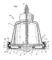
- a centrifuge 10 for separating the various components of whole blood includes a motor-driven chuck 1 for securing a closed cone-shaped (bell-shaped) separation bowl 2 whereby the chuck 1 and the separation bowl 2 secured thereto may rotate around a main (centrifuge) axis X A .
- the bowl 2 is provided with one or more inlet port(s) for the whole blood to be treated and one or more outlet port(s) through which separated blood components are extracted.
- the bowl 2 is provided with a convex (e.g. cone-shaped) lower end portion 22, surrounded by an outer cone-shaped flank 23, adapted to be coupled to the chuck 1.
- a convex (e.g. cone-shaped) lower end portion 22 surrounded by an outer cone-shaped flank 23, adapted to be coupled to the chuck 1.
- the chuck 1 comprises a chuck body 11 configured as a vat-shaped body with an internal bottom surface 12 and an external lower surface 13 facing the centrifuge motor.
- the internal bottom surface 12 and the external lower surface 13 will thus face the lower end portion 22 of the bowl 2 and the centrifuge motor, respectively.
- the chuck body 11 will thus be able to receive therein the lower end portion 22 of the separation bowl 2 with a peripheral rim 28 of the chuck surrounding the outer flank 23 of the separation bowl 2.
- the peripheral rim 28 has a continuous structure (e.g. is comprised of a complete ring-shaped or toroidal body). In an embodiment, the peripheral rim 28 has a discontinuous structure (e.g. include a plurality of spaced arc-shaped segments intended to co-operate as the fingers of a hand to clutch the separation bowl).
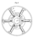
- the chuck body 11 is provided with a plurality of clutching systems to secure the bowl 2 to the chuck 1.
- These clutching systems may be angularly, equally spaced of 60° around the circumference of the chuck to secure the bowl 2 to the chuck 1 around the axis X A .
- the clutching systems are preferably present in number of six.
- the radial force exerted outwardly on the proximal body 16 may be transmitted via the intermediate translatory body or bodies 17, 18, 19 in the chain to the distal translatory body 20; the distal translatory body 20 will thus be urged towards the rotary axis X A to clutch the outer flank 23 of the separation bowl 2 and secure the bowl to the rotary chuck 1.
- the outer bottom flank of the separation bowl has a conical convex shape opening out towards the chuck 1.
- the inward radial force exerted by the distal translatory body 20 will thus develop a "vertical" component (i.e. a component in a direction parallel to the axis X A ) which will keep the bowl 2 firmly attached to the chuck 1.
- the channel 30 formed in the chuck body 11 exhibits a C-shaped path (i.e., more generally, an arc-shaped or arcuate path) including:
- the channel 30 and the portions 31, 32, 33 thereof "receiving" therein i.e. housing) the rotary bodies 16 to 20 (and the mass 15) means that the translatory bodies are confined within the channel(s) with the capability of at least slightly moving along the channel in order to perform the thrust (i.e. force) transmission effect from the proximal body 16 (i.e. from the centrifugal mass 15/spring 21) to the distal body 20 (i.e. to the flank 23 of the bowl 2).
- the translatory bodies are balls such as steel balls, but other translatory bodies able to transmit properly the movement and the force with low friction, such as e.g. rollers, may be used.
- the joint mass of the bodies housed in the proximal channel portion 31 is larger than the joint mass of the bodies housed in the distal channel portion 33 (i.e., in the exemplary embodiment shown, the distal translatory body 20).
- Such a difference in the masses can be obtained by relaying on the masses and/or the number of the individual bodies involved.
- the number of translatory bodies in the proximal portion 31 of the channel 30 may be higher than the number of translatory bodies in distal portion 33 of the channel 30.
- the proximal translatory body 16 may incorporate the role of the centrifugal mass 15, thus making it unnecessary to provide the centrifugal mass 15 as a separate component.
- the centrifugal force generated by the mass 15 acting on the proximal translatory body 16 in the horizontal channel 31 will be negligible.
- the elastic member (e.g. a spring) 21 will exert on the proximal translatory body 16 an elastic force directed outwardly, which - transmitted to the distal translatory body 20 via the intermediate translatory bodies 17, 18, 19 - will ensure that the distal translatory body 20 is pressed against the cone-shaped lower flank 23 of the bowl, with a force sufficient to keep the bowl 2 firmly attached to the chuck 1.
- the centrifugal force developed by the mass of bodies in the proximal portion 31 of the channel 30 will prevail against the centrifugal force developed by the mass of bodies in the distal portion 33 of the channel 30, causing the distal translatory body 20 to be firmly urged against the outer flank 23 of the bowl 2 to secure the bowl 2 against the chuck, with a force that i.a. increases as the rotational speed of the chuck increases.
- a convex conical sloped shape of the flank 23 at the lower end 22 of the bowl 2 will transform the inwardly directed force exerted by the distal translatory body 20 into a strong downward component i.e. a strong force in the direction of the axis X A directed towards the chuck 1 which will keep the bowl 2 firmly attached to the chuck 1.
- the bowl 2 is kept fixed, firmly in place and attached to the chuck 1, whatever the chuck rotational speed is.
- Coupling the bowl 2 to the (stationary) chuck 1 will merely involve sliding the lower portion of the bowl 2 into the vat-like cavity of the chuck by first causing the distal bodies 20 of the securing mechanisms to first spread apart against the moderate reaction force generated by the springs 21 and then snap-engage against the flank 23 again under the elastic force generated by the springs 21.
- a complementary movement to release the bowl from the elastic reaction exerted against the flank 23 by the translatory bodies 20 under the action of the springs 21 will permit to easily disengage the bowl 2 from the chuck 1.
- the chuck structure of this disclosure allows simpler manufacturing and assembly operations, since no levers or hinges are employed. Moreover, the chuck structure of this disclosure provides higher protection against an adverse environment preventing contamination from blood and dirt. In fact, when the bowl 2 is disengaged from the chuck 1, the distal translatory bodies 20 will hermetically close the channels 30 and seal the internal parts of the chuck to the outer environment.
Landscapes
- Engineering & Computer Science (AREA)
- Mechanical Engineering (AREA)
- Centrifugal Separators (AREA)
Claims (13)
- Ein Spannfutter (1), um einen Zentrifugaltrennbecher (2) um eine Rotationsachse (XA) zu drehen, wobei das Spannfutter (1) einen wannenförmigen Körper (11) zur Aufnahme eines unteren Endbereichs (22) des Trennbechers (2) in einer so befestigten Weise aufweist, dass eine Umfangskrempe (28) des Spannfutters (1) eine äußere Flanke (23) des Trennbechers (2) umgibt, wobei das Spannfutter wenigstens ein Kupplungssystem, das mit der Flanke des Trennbechers (2) bei der Befestigung des Trennbechers (2) an dem Spannfutter (1) zusammenwirkt, aufweist, dadurch gekennzeichnet, dass das Kupplungssystem umfasst:- einen Kanal (30), der in dem Futterkörper (11) ausgebildet ist, wobei der Kanal einen bogenförmigen Pfad innerhalb der Umfangskrempe (28) hat,- eine Kette von Schubkörpern (16, 17, 18, 19, 20), die innerhalb des Kanals (30) angeordnet sind, wobei die Kette von Schubkörpern einen proximalen Schubkörper (16) in der Kette und einen distalen Schubkörper (20) in der Kette aufweist, wobei eine Kraft (15, 16, 21), die auf den proximalen Körper (16) wirkt und von der Rotationsachse (XA) nach außen gerichtet ist, durch die Kette von Schubkörpern auf den distalen Schubkörper (20) in der Kette übertragen wird, um den distalen Schubkörper (16) in Richtung der Rotationsachse (XA) nach innen zu drücken, um so die äußere Flanke (23) des Trennbechers (2) zu erfassen, wodurch der Trennbecher (2) an dem Rotationsspannfutter (1) befestigt wird.
- Das Spannfutter von Anspruch 1, umfassend ein elastisches Element (21), das auf den proximalen Körper (16) wenigstens einen Teil der in Bezug auf die Rotationsachse (XA) nach außen gerichteten Kraft ausübt.
- Das Spannfutter von Anspruch 1, umfassend eine Zentrifugalmasse (15), um auf den proximalen Körper (16) während der Rotation um die Rotationsachse (XA) wenigstens einen Teil der in Bezug auf die Rotationsachse (XA) nach außen gerichteten Kraft auszuüben.
- Das Spannfutter von Anspruch 1, umfassend sowohl eine Zentrifugalmasse (15) als auch ein elastisches Element (21), welches die Zentrifugalmasse (15) vorspannt, aufweist, wobei die Zentrifugalmasse (15) und das elastische Element (21) auf den proximalen Körper (16) entsprechende Komponenten der in Bezug auf die Rotationsachse (XA) nach außen gerichteten Kraft ausüben.
- Das Spannfutter nach Anspruch 3 oder 4, worin die Zentrifugalmasse (15) ein von dem proximalen Körper (16) getrennter Körper ist.
- Das Spannfutter nach Anspruch 5, worin die Zentrifugalmasse (15) eine Stange ist, die in einer radialen Bohrung in dem Spannfutter verschiebbar angeordnet ist.
- Das Spannfutter nach einem der vorherigen Ansprüche, worin der Kanal (30), der in dem Spannfutterkörper (11) ausgebildet ist und einen bogenförmigen Pfad hat, umfasst:- einen proximalen Bereich (31), der sich radial zu der Achse (XA) erstreckt, um den proximalen Schubkörper (16) aufzunehmen;- einen Zwischenbereich (32), um Schubkörper (17, 18, 19) in der Kette zwischen dem proximalen (16) und dem distalen (20) Schubkörper in der Kette aufzunehmen, wobei der Zwischenbereich (32) des Kanals (30) sich in der Richtung der Achse (XA) erstreckt; und- einen distalen Bereich (33), der sich radial zu der Achse (XA) erstreckt, um den distalen Schubkörper (20) in der Kette aufzunehmen.
- Das Spannfutter von Anspruch 7, worin der proximale Bereich (31) und der distale Bereich (33) in dem Kanal (30) Körper (15, 16, 20) aufnehmen, die während der Rotation um die Rotationsachse (XA) einer Zentrifugalkraft ausgesetzt sind, und worin die Gesamtmasse derjenigen der einer Zentrifugalkraft ausgesetzten Körper (15, 16), die in dem proximalen Bereich (31) des Kanals (30) angeordnet sind, höher ist als die Gesamtmasse derjenigen der einer Zentrifugalkraft ausgesetzten Körper (20), die in dem distalen Bereich (33) des Kanals angeordnet sind.
- Das Spannfutter nach irgendeinem der vorherigen Ansprüche, das es eine Mehrzahl der Kupplungssysteme aufweist, die gleichwinklig beabstandet um die Rotationsachse (XA) angeordnet sind.
- Das Spannfutter nach irgendeinem der vorherigen Ansprüche, welches sechs der Kupplungssysteme aufweist.
- Das Spannfutter nach irgendeinem der vorherigen Ansprüche, worin die Umfangskrempe (28) des Spannfutters (1) kontinuierlich ist.
- Das Spannfutter nach irgendeinem der vorherigen Ansprüche, worin die Schubkörper (16 bis 20) in der Form von Kugeln vorhanden sind.
- Die Kombination des Spannfutters nach einem der vorherigen Ansprüche und des Zentrifugaltrennbechers (2), worin die äußere Flanke (23) des Trennbechers (2) eine konvexe konische Form hat, die in Richtung des Spannfutters (1) öffnet, wobei die Kraft, welche durch die Kette von Schubkörpern auf den distalen Schubkörper (20) übertragen wird und den distalen Schubkörper (20) nach innen in Richtung der Rotationsachse (XA) drückt, um die äußere Flanke (23) zu ergreifen, eine Kraft ergibt, welche den Trennbecher (2) gegen das Rotationsspannfutter drückt.
Priority Applications (6)
| Application Number | Priority Date | Filing Date | Title |
|---|---|---|---|
| EP08157932A EP2138237B1 (de) | 2008-06-10 | 2008-06-10 | Sicherungsmechanismus, insbesondere für Bluttrennungszentrifugen und dergleichen |
| DE602008004637T DE602008004637D1 (de) | 2008-06-10 | 2008-06-10 | Sicherungsmechanismus, insbesondere für Bluttrennungszentrifugen und dergleichen |
| US12/472,825 US7993257B2 (en) | 2008-06-10 | 2009-05-27 | Securing mechanism, particularly for blood separation centrifuges and the like |
| JP2009138348A JP5199186B2 (ja) | 2008-06-10 | 2009-06-09 | 取付機構、特に血液を分離する遠心分離機用の取付機構 |
| US13/172,220 US8262552B2 (en) | 2008-06-10 | 2011-06-29 | Securing mechanism, particularly for blood separation centrifuges and the like |
| US13/587,153 US8485957B2 (en) | 2008-06-10 | 2012-08-16 | Securing mechanism, particularly for blood separation centrifuges and the like |
Applications Claiming Priority (1)
| Application Number | Priority Date | Filing Date | Title |
|---|---|---|---|
| EP08157932A EP2138237B1 (de) | 2008-06-10 | 2008-06-10 | Sicherungsmechanismus, insbesondere für Bluttrennungszentrifugen und dergleichen |
Publications (2)
| Publication Number | Publication Date |
|---|---|
| EP2138237A1 EP2138237A1 (de) | 2009-12-30 |
| EP2138237B1 true EP2138237B1 (de) | 2011-01-19 |
Family
ID=39870607
Family Applications (1)
| Application Number | Title | Priority Date | Filing Date |
|---|---|---|---|
| EP08157932A Active EP2138237B1 (de) | 2008-06-10 | 2008-06-10 | Sicherungsmechanismus, insbesondere für Bluttrennungszentrifugen und dergleichen |
Country Status (4)
| Country | Link |
|---|---|
| US (3) | US7993257B2 (de) |
| EP (1) | EP2138237B1 (de) |
| JP (1) | JP5199186B2 (de) |
| DE (1) | DE602008004637D1 (de) |
Cited By (3)
| Publication number | Priority date | Publication date | Assignee | Title |
|---|---|---|---|---|
| US8506825B2 (en) | 2006-11-27 | 2013-08-13 | Sorin Group Italia S.R.L. | Method and apparatus for controlling the flow rate of washing solution during the washing step in a blood centrifugation bowl |
| US9308314B2 (en) | 2011-04-08 | 2016-04-12 | Sorin Group Italia S.R.L. | Disposable device for centrifugal blood separation |
| US10039876B2 (en) | 2014-04-30 | 2018-08-07 | Sorin Group Italia S.R.L. | System for removing undesirable elements from blood using a first wash step and a second wash step |
Families Citing this family (5)
| Publication number | Priority date | Publication date | Assignee | Title |
|---|---|---|---|---|
| US7998052B2 (en) * | 2006-03-07 | 2011-08-16 | Jacques Chammas | Rotor defining a fluid separation chamber of varying volume |
| EP2138237B1 (de) * | 2008-06-10 | 2011-01-19 | Sorin Group Italia S.r.l. | Sicherungsmechanismus, insbesondere für Bluttrennungszentrifugen und dergleichen |
| US9126211B2 (en) * | 2009-07-24 | 2015-09-08 | Durr Systems Gmbh | Rotary atomizer comprising an atomizer bell and a retainer |
| WO2016063111A1 (en) | 2014-10-23 | 2016-04-28 | Sorin Group Italia S.R.L. | Integrated autotransfusion bowl and fluid line organizer |
| WO2024206586A2 (en) * | 2023-03-29 | 2024-10-03 | University Of Virginia Patent Foundation | Systems and methods for integrated near-isothermal compressed air energy storage |
Family Cites Families (57)
| Publication number | Priority date | Publication date | Assignee | Title |
|---|---|---|---|---|
| US1385306A (en) * | 1918-04-08 | 1921-07-19 | Courtaulds Ltd | Spinning-box for artificial silk |
| US2536793A (en) * | 1945-03-02 | 1951-01-02 | Separator Ab | Sealing device for centrifugal separators |
| US3317127A (en) * | 1945-03-02 | 1967-05-02 | Little Inc A | Centrifuge |
| US2835517A (en) * | 1953-09-25 | 1958-05-20 | Uster Spindel Motoren Maschf | Holding device |
| US3409213A (en) * | 1967-01-23 | 1968-11-05 | 500 Inc | Rotary seal and centrifuge incorporation |
| US3565330A (en) * | 1968-07-11 | 1971-02-23 | Cryogenic Technology Inc | Rotary seal and centrifuge incorporating same |
| US3785549A (en) * | 1972-07-31 | 1974-01-15 | Haemonetics Corp | Centrifuge chuck for disposable, snap-in centrifuge rotor |
| US4140268A (en) * | 1977-03-15 | 1979-02-20 | Haemo-Transfer S.A. | Centrifugating device for biological liquids, having a rotatable container, and supporting bracket therefor |
| US4795419A (en) * | 1985-10-11 | 1989-01-03 | Kardiothor, Inc. | Centrifuge |
| US4718888A (en) * | 1986-03-10 | 1988-01-12 | Cardiovascular Systems, Inc. | Centrifuge bowl mount |
| US4668214A (en) | 1986-06-09 | 1987-05-26 | Electromedics, Inc. | Method of washing red blood cells |
| JP2881305B2 (ja) | 1986-08-11 | 1999-04-12 | バクスター、インターナショナル、インコーポレイテッド | 血球洗浄システムおよび方法 |
| IT1202514B (it) * | 1987-02-10 | 1989-02-09 | Dideco Spa | Mandrino per il fissaggio di cella per la centrifugazione del sangue,e simili |
| US4889524A (en) * | 1987-09-04 | 1989-12-26 | Haemonetics Corporation | Portable centrifuge apparatus |
| DE3822506C1 (de) * | 1988-07-04 | 1989-07-27 | Paul Forkardt Gmbh & Co Kg, 4000 Duesseldorf, De | |
| IT1230356B (it) * | 1989-07-14 | 1991-10-18 | Dideco Spa | Dispositivo per il bloccaggio su mandrino di cella per la centrifugazione del sangue. |
| IT1231023B (it) * | 1989-07-31 | 1991-11-08 | Dideco Spa | Dispositivo di chiusura del pozzetto di contenimento di cella per la centrifugazione del sangue in una macchina centrifuga |
| US5137221A (en) * | 1990-10-04 | 1992-08-11 | Axis Usa, Inc. | Rapidly changeable chucks for holding stators in stator processing apparatus |
| US5273517A (en) | 1991-07-09 | 1993-12-28 | Haemonetics Corporation | Blood processing method and apparatus with disposable cassette |
| DE4126341C1 (de) | 1991-08-09 | 1993-01-28 | Fresenius Ag, 6380 Bad Homburg, De | |
| US5730883A (en) | 1991-12-23 | 1998-03-24 | Baxter International Inc. | Blood processing systems and methods using apparent hematocrit as a process control parameter |
| US5423738A (en) | 1992-03-13 | 1995-06-13 | Robinson; Thomas C. | Blood pumping and processing system |
| EP0568191B1 (de) * | 1992-04-29 | 1997-05-28 | Cobe Laboratories, Inc. | Zentrifuge mit einem einzigen Schwingarm zur Halterung eines Statorrohres |
| US5385539A (en) | 1992-06-30 | 1995-01-31 | Advanced Haemotechnologies | Apparatus for monitoring hematocrit levels of blood |
| SE9202937D0 (sv) | 1992-10-07 | 1992-10-07 | Siemens Elema Ab | Frekvensadaptiv hjaertstimulator |
| CH687505A5 (fr) * | 1993-01-29 | 1996-12-31 | Elp Rochat | Séparateur centrifuge pour fluides. |
| US5383911A (en) | 1993-01-29 | 1995-01-24 | Siemens Pacesetter, Inc. | Rate-responsive pacemaker having selectable response to arm movement and pedal impacts |
| WO1994025086A1 (en) | 1993-04-27 | 1994-11-10 | Haemonetics Corporation | Apheresis apparatus and method |
| US5379775A (en) | 1993-10-15 | 1995-01-10 | Medtronic, Inc. | Low amplitude pacing artifact detection apparatus and method using isolation amplifier to minimize distortion |
| US5505683A (en) * | 1993-12-10 | 1996-04-09 | Haemonetics Corporation | Centrifuge bowl gripping apparatus having a retaining arm with a stationary jaw and a moveable jaw |
| US5478479A (en) | 1994-05-20 | 1995-12-26 | Haemonetics Corporation | Two-stage cell wash process controlled by optical sensor |
| US5733253A (en) * | 1994-10-13 | 1998-03-31 | Transfusion Technologies Corporation | Fluid separation system |
| US5591113A (en) * | 1994-10-31 | 1997-01-07 | Cobe Laboratories, Inc. | Centrifugally assisted centrifuge bowl mount |
| US5658231A (en) | 1995-09-21 | 1997-08-19 | Haemonetics Corporation | Mechanism for securing a separation bowl to a mechanical chuck |
| NZ325024A (en) * | 1995-12-07 | 2000-02-28 | Bristol Myers Squibb Co | centrifuge apparatus with container locking means |
| US5851169A (en) * | 1996-01-31 | 1998-12-22 | Medtronic Electromedics, Inc. | Rotary plate and bowl clamp for blood centrifuge |
| JPH09320158A (ja) * | 1996-05-27 | 1997-12-12 | Pioneer Electron Corp | ディスクチャック機構 |
| DE19746914C2 (de) | 1996-10-25 | 1999-07-22 | Peter Dr Geigle | Zentrifugiereinheit |
| WO1998029149A1 (en) | 1997-01-03 | 1998-07-09 | Shettigar U Ramakrishna | Intraoperative blood salvaging system and method |
| US5876611A (en) | 1997-06-16 | 1999-03-02 | Shettigar; U. Ramakrishna | Intraoperative blood salvaging system and method |
| SE9700495D0 (sv) | 1997-02-12 | 1997-02-12 | Omega Medicinteknik Ab | Metod och rundpåsesystem samt centrifug för behandling av blod |
| US5964690A (en) * | 1997-03-19 | 1999-10-12 | Medtronic, Inc. | Mechanism for fixing a blood centrifuge bowl to a rotating spindle |
| JP3516400B2 (ja) | 1997-05-20 | 2004-04-05 | ザイムクエスト,インク. | 細胞処理システム |
| US5919125A (en) | 1997-07-11 | 1999-07-06 | Cobe Laboratories, Inc. | Centrifuge bowl for autologous blood salvage |
| DE19802321C2 (de) | 1998-01-23 | 2000-05-11 | Fresenius Ag | Verfahren und Vorrichtung zur Aufbereitung von intra- oder postoperativen Blutverlusten für die Autotransfusion |
| IT1302015B1 (it) | 1998-08-07 | 2000-07-20 | Dideco Spa | Sistema di controllo automatico di cella per la centrifugazione delsangue. |
| US6629919B2 (en) | 1999-06-03 | 2003-10-07 | Haemonetics Corporation | Core for blood processing apparatus |
| JP4064014B2 (ja) * | 1999-09-01 | 2008-03-19 | 株式会社テック・ヤスダ | 口金 |
| US6605028B2 (en) | 2001-04-09 | 2003-08-12 | Medtronic, Inc. | Blood centrifuge having integral heating to control cellular component temperature |
| ITMI20010899A1 (it) | 2001-04-30 | 2002-10-30 | Dideco Spa | Sistema di controllo della fase di lavaggio in cella per la centrifugazione del sangue |
| US7186230B2 (en) | 2002-03-04 | 2007-03-06 | Therakos, Inc | Method and apparatus for the continuous separation of biological fluids into components |
| ITMI20031715A1 (it) | 2003-09-05 | 2005-03-06 | Dideco Spa | Dispositivo di comando nella raccolta differenziata dei |
| JP4304031B2 (ja) * | 2003-09-11 | 2009-07-29 | テルモ株式会社 | 遠心分離器の回転駆動装置 |
| US7998052B2 (en) * | 2006-03-07 | 2011-08-16 | Jacques Chammas | Rotor defining a fluid separation chamber of varying volume |
| US8506825B2 (en) | 2006-11-27 | 2013-08-13 | Sorin Group Italia S.R.L. | Method and apparatus for controlling the flow rate of washing solution during the washing step in a blood centrifugation bowl |
| JP2009291335A (ja) * | 2008-06-04 | 2009-12-17 | Terumo Corp | 遠心分離装置及び血液成分採取装置 |
| EP2138237B1 (de) * | 2008-06-10 | 2011-01-19 | Sorin Group Italia S.r.l. | Sicherungsmechanismus, insbesondere für Bluttrennungszentrifugen und dergleichen |
-
2008
- 2008-06-10 EP EP08157932A patent/EP2138237B1/de active Active
- 2008-06-10 DE DE602008004637T patent/DE602008004637D1/de active Active
-
2009
- 2009-05-27 US US12/472,825 patent/US7993257B2/en active Active
- 2009-06-09 JP JP2009138348A patent/JP5199186B2/ja not_active Expired - Fee Related
-
2011
- 2011-06-29 US US13/172,220 patent/US8262552B2/en active Active
-
2012
- 2012-08-16 US US13/587,153 patent/US8485957B2/en active Active
Cited By (4)
| Publication number | Priority date | Publication date | Assignee | Title |
|---|---|---|---|---|
| US8506825B2 (en) | 2006-11-27 | 2013-08-13 | Sorin Group Italia S.R.L. | Method and apparatus for controlling the flow rate of washing solution during the washing step in a blood centrifugation bowl |
| US9308314B2 (en) | 2011-04-08 | 2016-04-12 | Sorin Group Italia S.R.L. | Disposable device for centrifugal blood separation |
| US10039876B2 (en) | 2014-04-30 | 2018-08-07 | Sorin Group Italia S.R.L. | System for removing undesirable elements from blood using a first wash step and a second wash step |
| US10293098B2 (en) | 2014-04-30 | 2019-05-21 | Sorin Group Italia S.R.L. | System for removing undesirable elements from blood using a first wash step and a second wash step |
Also Published As
| Publication number | Publication date |
|---|---|
| JP5199186B2 (ja) | 2013-05-15 |
| JP2010042398A (ja) | 2010-02-25 |
| DE602008004637D1 (de) | 2011-03-03 |
| US20090305863A1 (en) | 2009-12-10 |
| US20110256999A1 (en) | 2011-10-20 |
| US7993257B2 (en) | 2011-08-09 |
| EP2138237A1 (de) | 2009-12-30 |
| US8485957B2 (en) | 2013-07-16 |
| US8262552B2 (en) | 2012-09-11 |
| US20130079211A1 (en) | 2013-03-28 |
Similar Documents
| Publication | Publication Date | Title |
|---|---|---|
| US8485957B2 (en) | Securing mechanism, particularly for blood separation centrifuges and the like | |
| RU2230475C2 (ru) | Съемная опорная система инструмента для обработки пищевых продуктов, предназначенная для смесителей, установок по обработке пищевых продуктов, мельниц и подобных устройств | |
| CN104565280B (zh) | 机械操控式强制联锁差速器 | |
| JP2010042398A5 (de) | ||
| US8425142B2 (en) | Connecting arrangement and articulated shaft comprising same | |
| CN102292161B (zh) | 离心分离机、离心分离机用转子 | |
| KR20170045333A (ko) | 원심 분리기용 신속 마개 | |
| CA2562342A1 (en) | Capping device with quick release mechanism and methods of releasing and re-connecting | |
| US6129392A (en) | Coupler for tubular-shaft instruments | |
| JP4187273B2 (ja) | 血液遠心分離機用の容器を回転主軸に固定するための機構 | |
| WO2008049091A3 (en) | Apparatus and system for automatic centrifugal engagement of a pressure plate | |
| US11168742B2 (en) | Twin plate separation systems | |
| CA1185505A (en) | Quick-release mechanical coupling for a kitchen appliance | |
| US7464450B2 (en) | Attachment and release apparatus and method | |
| CN113412159B (zh) | 连接结构 | |
| WO2014179124A1 (en) | One-way clutch with conical strut | |
| CA2736719A1 (en) | Cam operated valve | |
| US6024687A (en) | Centrifuge rotor lock | |
| US9551381B2 (en) | Device for driving a rotary tool for a food processing appliance and food processing appliance provided with such a driving device | |
| JP7808924B2 (ja) | 支持ボルトによって荷物を吊具に結合するための連結装置 | |
| SE524921C2 (sv) | En medbringningsanordning för en centrifugator | |
| US4269422A (en) | Quick release locking chuck mechanism | |
| EP3322364B1 (de) | Zusätzlicher griff und chirurgisches instrumentenset mit solch einem zusätzlichen griff | |
| WO2007134157A2 (en) | Driving wheel assembly | |
| JPS6141017A (ja) | 駆動軸 |
Legal Events
| Date | Code | Title | Description |
|---|---|---|---|
| PUAI | Public reference made under article 153(3) epc to a published international application that has entered the european phase |
Free format text: ORIGINAL CODE: 0009012 |
|
| AK | Designated contracting states |
Kind code of ref document: A1 Designated state(s): AT BE BG CH CY CZ DE DK EE ES FI FR GB GR HR HU IE IS IT LI LT LU LV MC MT NL NO PL PT RO SE SI SK TR |
|
| AX | Request for extension of the european patent |
Extension state: AL BA MK RS |
|
| 17P | Request for examination filed |
Effective date: 20100330 |
|
| GRAP | Despatch of communication of intention to grant a patent |
Free format text: ORIGINAL CODE: EPIDOSNIGR1 |
|
| AKX | Designation fees paid |
Designated state(s): DE FR GB IT NL |
|
| GRAS | Grant fee paid |
Free format text: ORIGINAL CODE: EPIDOSNIGR3 |
|
| GRAA | (expected) grant |
Free format text: ORIGINAL CODE: 0009210 |
|
| AK | Designated contracting states |
Kind code of ref document: B1 Designated state(s): DE FR GB IT NL |
|
| REG | Reference to a national code |
Ref country code: GB Ref legal event code: FG4D |
|
| REF | Corresponds to: |
Ref document number: 602008004637 Country of ref document: DE Date of ref document: 20110303 Kind code of ref document: P |
|
| REG | Reference to a national code |
Ref country code: DE Ref legal event code: R096 Ref document number: 602008004637 Country of ref document: DE Effective date: 20110303 |
|
| REG | Reference to a national code |
Ref country code: NL Ref legal event code: T3 |
|
| PLBE | No opposition filed within time limit |
Free format text: ORIGINAL CODE: 0009261 |
|
| STAA | Information on the status of an ep patent application or granted ep patent |
Free format text: STATUS: NO OPPOSITION FILED WITHIN TIME LIMIT |
|
| 26N | No opposition filed |
Effective date: 20111020 |
|
| REG | Reference to a national code |
Ref country code: DE Ref legal event code: R097 Ref document number: 602008004637 Country of ref document: DE Effective date: 20111020 |
|
| REG | Reference to a national code |
Ref country code: FR Ref legal event code: PLFP Year of fee payment: 9 |
|
| REG | Reference to a national code |
Ref country code: FR Ref legal event code: PLFP Year of fee payment: 10 |
|
| REG | Reference to a national code |
Ref country code: FR Ref legal event code: PLFP Year of fee payment: 11 |
|
| PGFP | Annual fee paid to national office [announced via postgrant information from national office to epo] |
Ref country code: NL Payment date: 20190612 Year of fee payment: 12 |
|
| REG | Reference to a national code |
Ref country code: NL Ref legal event code: MM Effective date: 20200701 |
|
| PG25 | Lapsed in a contracting state [announced via postgrant information from national office to epo] |
Ref country code: NL Free format text: LAPSE BECAUSE OF NON-PAYMENT OF DUE FEES Effective date: 20200701 |
|
| REG | Reference to a national code |
Ref country code: FR Ref legal event code: PLFP Year of fee payment: 16 |
|
| P01 | Opt-out of the competence of the unified patent court (upc) registered |
Effective date: 20230516 |
|
| PGFP | Annual fee paid to national office [announced via postgrant information from national office to epo] |
Ref country code: DE Payment date: 20250402 Year of fee payment: 18 |
|
| PGFP | Annual fee paid to national office [announced via postgrant information from national office to epo] |
Ref country code: GB Payment date: 20250401 Year of fee payment: 18 |
|
| PGFP | Annual fee paid to national office [announced via postgrant information from national office to epo] |
Ref country code: IT Payment date: 20250522 Year of fee payment: 18 |
|
| PGFP | Annual fee paid to national office [announced via postgrant information from national office to epo] |
Ref country code: FR Payment date: 20250401 Year of fee payment: 18 |