EP0656824B1 - Tete de distribution destinee a former un profile tubulaire a partir d'une ou plusieurs coulees de matiere thermoplastique extrudee - Google Patents
Tete de distribution destinee a former un profile tubulaire a partir d'une ou plusieurs coulees de matiere thermoplastique extrudee Download PDFInfo
- Publication number
- EP0656824B1 EP0656824B1 EP93921122A EP93921122A EP0656824B1 EP 0656824 B1 EP0656824 B1 EP 0656824B1 EP 93921122 A EP93921122 A EP 93921122A EP 93921122 A EP93921122 A EP 93921122A EP 0656824 B1 EP0656824 B1 EP 0656824B1
- Authority
- EP
- European Patent Office
- Prior art keywords
- distributor head
- flow channel
- outlet
- flow
- inlet
- Prior art date
- Legal status (The legal status is an assumption and is not a legal conclusion. Google has not performed a legal analysis and makes no representation as to the accuracy of the status listed.)
- Expired - Lifetime
Links
- 239000012815 thermoplastic material Substances 0.000 title claims abstract description 7
- 239000000463 material Substances 0.000 claims abstract description 32
- 230000007423 decrease Effects 0.000 claims description 4
- 238000011144 upstream manufacturing Methods 0.000 claims description 3
- 239000004033 plastic Substances 0.000 abstract description 10
- 229920003023 plastic Polymers 0.000 abstract description 10
- 239000010410 layer Substances 0.000 description 7
- 230000002411 adverse Effects 0.000 description 3
- 238000010276 construction Methods 0.000 description 3
- 239000004800 polyvinyl chloride Substances 0.000 description 3
- 239000000654 additive Substances 0.000 description 2
- 230000000694 effects Effects 0.000 description 2
- 238000004519 manufacturing process Methods 0.000 description 2
- 229920000915 polyvinyl chloride Polymers 0.000 description 2
- 229910000831 Steel Inorganic materials 0.000 description 1
- 230000001154 acute effect Effects 0.000 description 1
- 238000001816 cooling Methods 0.000 description 1
- 238000000354 decomposition reaction Methods 0.000 description 1
- 238000001125 extrusion Methods 0.000 description 1
- 238000000034 method Methods 0.000 description 1
- 238000003801 milling Methods 0.000 description 1
- 238000004886 process control Methods 0.000 description 1
- 230000001737 promoting effect Effects 0.000 description 1
- 239000002356 single layer Substances 0.000 description 1
- 239000007787 solid Substances 0.000 description 1
- 239000010959 steel Substances 0.000 description 1
- 239000000126 substance Substances 0.000 description 1
- 230000007704 transition Effects 0.000 description 1
Images


Classifications
-
- B—PERFORMING OPERATIONS; TRANSPORTING
- B29—WORKING OF PLASTICS; WORKING OF SUBSTANCES IN A PLASTIC STATE IN GENERAL
- B29C—SHAPING OR JOINING OF PLASTICS; SHAPING OF MATERIAL IN A PLASTIC STATE, NOT OTHERWISE PROVIDED FOR; AFTER-TREATMENT OF THE SHAPED PRODUCTS, e.g. REPAIRING
- B29C48/00—Extrusion moulding, i.e. expressing the moulding material through a die or nozzle which imparts the desired form; Apparatus therefor
- B29C48/25—Component parts, details or accessories; Auxiliary operations
- B29C48/36—Means for plasticising or homogenising the moulding material or forcing it through the nozzle or die
- B29C48/50—Details of extruders
- B29C48/695—Flow dividers, e.g. breaker plates
- B29C48/70—Flow dividers, e.g. breaker plates comprising means for dividing, distributing and recombining melt flows
- B29C48/705—Flow dividers, e.g. breaker plates comprising means for dividing, distributing and recombining melt flows in the die zone, e.g. to create flow homogeneity
-
- B—PERFORMING OPERATIONS; TRANSPORTING
- B29—WORKING OF PLASTICS; WORKING OF SUBSTANCES IN A PLASTIC STATE IN GENERAL
- B29C—SHAPING OR JOINING OF PLASTICS; SHAPING OF MATERIAL IN A PLASTIC STATE, NOT OTHERWISE PROVIDED FOR; AFTER-TREATMENT OF THE SHAPED PRODUCTS, e.g. REPAIRING
- B29C48/00—Extrusion moulding, i.e. expressing the moulding material through a die or nozzle which imparts the desired form; Apparatus therefor
- B29C48/03—Extrusion moulding, i.e. expressing the moulding material through a die or nozzle which imparts the desired form; Apparatus therefor characterised by the shape of the extruded material at extrusion
- B29C48/09—Articles with cross-sections having partially or fully enclosed cavities, e.g. pipes or channels
-
- B—PERFORMING OPERATIONS; TRANSPORTING
- B29—WORKING OF PLASTICS; WORKING OF SUBSTANCES IN A PLASTIC STATE IN GENERAL
- B29C—SHAPING OR JOINING OF PLASTICS; SHAPING OF MATERIAL IN A PLASTIC STATE, NOT OTHERWISE PROVIDED FOR; AFTER-TREATMENT OF THE SHAPED PRODUCTS, e.g. REPAIRING
- B29C48/00—Extrusion moulding, i.e. expressing the moulding material through a die or nozzle which imparts the desired form; Apparatus therefor
- B29C48/16—Articles comprising two or more components, e.g. co-extruded layers
- B29C48/18—Articles comprising two or more components, e.g. co-extruded layers the components being layers
- B29C48/21—Articles comprising two or more components, e.g. co-extruded layers the components being layers the layers being joined at their surfaces
-
- B—PERFORMING OPERATIONS; TRANSPORTING
- B29—WORKING OF PLASTICS; WORKING OF SUBSTANCES IN A PLASTIC STATE IN GENERAL
- B29C—SHAPING OR JOINING OF PLASTICS; SHAPING OF MATERIAL IN A PLASTIC STATE, NOT OTHERWISE PROVIDED FOR; AFTER-TREATMENT OF THE SHAPED PRODUCTS, e.g. REPAIRING
- B29C48/00—Extrusion moulding, i.e. expressing the moulding material through a die or nozzle which imparts the desired form; Apparatus therefor
- B29C48/25—Component parts, details or accessories; Auxiliary operations
- B29C48/30—Extrusion nozzles or dies
- B29C48/32—Extrusion nozzles or dies with annular openings, e.g. for forming tubular articles
- B29C48/335—Multiple annular extrusion nozzles in coaxial arrangement, e.g. for making multi-layered tubular articles
- B29C48/337—Multiple annular extrusion nozzles in coaxial arrangement, e.g. for making multi-layered tubular articles the components merging at a common location
- B29C48/338—Multiple annular extrusion nozzles in coaxial arrangement, e.g. for making multi-layered tubular articles the components merging at a common location using a die with concentric parts, e.g. rings, cylinders
-
- B—PERFORMING OPERATIONS; TRANSPORTING
- B29—WORKING OF PLASTICS; WORKING OF SUBSTANCES IN A PLASTIC STATE IN GENERAL
- B29C—SHAPING OR JOINING OF PLASTICS; SHAPING OF MATERIAL IN A PLASTIC STATE, NOT OTHERWISE PROVIDED FOR; AFTER-TREATMENT OF THE SHAPED PRODUCTS, e.g. REPAIRING
- B29C48/00—Extrusion moulding, i.e. expressing the moulding material through a die or nozzle which imparts the desired form; Apparatus therefor
- B29C48/03—Extrusion moulding, i.e. expressing the moulding material through a die or nozzle which imparts the desired form; Apparatus therefor characterised by the shape of the extruded material at extrusion
- B29C48/13—Articles with a cross-section varying in the longitudinal direction, e.g. corrugated pipes
Definitions
- the invention relates to a distributor head for forming a tubular profile from one or more streams of extruded thermoplastic material according to the preamble of claim 1.
- extruders which are connected at their output side to a distributor head are used to produce tubular profiles from thermoplastic materials.
- said distributor head is generally positioned in line with the extruder, so that the material stream from the extruder passes through in a virtually rectilinear manner.
- distributor heads are also known in which the direction of the material stream is altered. Said distributor heads are generally referred to as "crossheads".
- crossheads of this type have the advantage, inter alia, that the interior of the extruded tube can be accessed easily, for example in order to fit a cooled core.
- DE-U-1 927 405 discloses such a crosshead, which publication serves as the basis for the preamble of claim 1.
- the flow channel system of this known crosshead is formed through providing a pattern of grooves in the outer surface of a cylindrical mandrel of the head. This mandrel fits thight in an annular body of the crosshead.
- the flow channels of this known crosshead have a curvature corresponding to the diameter of the mandrel, when considering the cross-section of the head. Furthermore the flow channels have a rectangular cross-section with sharp corners. The curvature of the flow channels and the sharp corners lead to non-uniformity of the flow of the plastic material.
- the material stream fed in through this inlet orifice is separated in an annular chamber into a number of branch streams and downstream thereof, said branch streams are combined to form a closed ring at the outlet orifice.
- the material introduced into this distributor head at the respective inlet orifice flows to the associated outlet orifice along different paths.
- the disadvantage in this case is that these flow paths have a mutually different flow resistance.
- the fact that the length of the different flow paths may differ appreciably is disadvantageous.
- the residence time of the plastics material inside the distributor head varies and is difficult to determine, which has an adverse effect on the process control and process adjustment.
- a sensitive material such as, for example, normal rigid polyvinylchloride (PVC) can be processed using a "crosshead" only if particular attention is paid to the additives which are mixed in with the PVC in order to ensure the necessary stability.
- PVC normal rigid polyvinylchloride
- these additives are expensive, adversely affect the properties of the material after extrusion and in many cases pollute the environment.
- the object of the invention is therefore to overcome the abovementioned disadvantages.
- the invention provides a distributor head according to claim 1.
- the distributor head according to the invention prevents the occurence of "hot spots", i.e. sites having an excessively high temperature.
- the cross-sectional areas of the flow channels downstream of a branching are equal and together are essentially equal to the cross-sectional area of the flow channel upstream of the branching.
- the fact that the total cross-sectional area remains equal ensures that the rate of flow of the material does not drop below a predetermined lower limit.
- annular channel is connected to an outlet orifice, the cross-sectional area of which channel decreases in a first zone between the outlet orifice and a throat section and in a second zone downstream of the throat section increases in such a manner that the flow rate of a material stream in the first or second zone increases or decreases, respectively, by a maximum factor of 5 per second.
- a higher deformation per unit time of the plastics material stream would give rise to fracturing of the material.
- the smallest angle which is formed by the flow channel upstream of the branching and a flow channel downstream of said branching is more than 90 degrees.
- the material does not flow at too acute an angle and that the flow rate does not differ locally to too large an extent with the result that the material tends to decompose.
- the distributor head comprises a number of bodies, each body being provided with all the flow channels associated with one branching stage.
- the bodies are preferably disc-shaped. This ensures that the flow channels can be provided in each disc in a simple manner and thus enables a flow channel system of inherently complicated design to be produced. In this arrangement, it is also possible to use certain discs in more than one flow channel system and for different tube profiles. The flow channels can likewise be cleaned in a simple manner.
- the bodies are fixed in the distributor head by means of clamping rings engaging on the outer periphery thereof and a core extending through an axial bore in the bodies. Assembly and disassembly can thus take place in a simple manner.
- the distributor head has a plurality of concentric outlet orifices and a number of inlet orifices.
- one inlet orifice it is possible, for example, for one inlet orifice to be connected to two flow channel systems in order to form the inner and the outer layer of a tube profile whose wall consists of three layers.
- one extruder may, for example, be connected to two inlet orifices by means of a manifold.
- Figure 1 shows a distributor head which is referred to in its entirety by reference numeral 1.
- Three extruders can be connected to base part 2 for forming a tube profile having a three-layered wall.
- the distributor head comprises two disc-shaped bodies 3, 4.
- the disc-shaped bodies can be fastened in the middle to the base part 2.
- a ring 6 is screwed onto the outer periphery of base part 2, which ring is provided with a circular groove on its outside.
- a clamping ring 7 consisting of two halves in said groove and in a groove of the disc-shaped body 4 are fastened to the base part 2.
- a die body (not shown) may be attached to the distributor head by means of clamping ring 8.
- the rings 9, a portion of which has been partly omitted, are attached to the disc-shaped body 4 by means of screws.
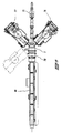
- Figure 2 shows a wire model of the distributor head 1 from Figure 1, showing, in particular, the construction and the position of the flow channel systems.
- Three extruders may be connected to said distributor head at inlet orifices 10, 12, 14.
- the centre line of the extruder for forming the intermediate layer of the wall of the tube profile to be formed coincides with the centre line 16 of the distributor head.
- the centre lines of the extruders for forming the inner and outer layer, respectively, are at an angle relative to the centre line of the distributor head.
- the distributor head comprises three flow channel systems, 30, 32 and 34 for forming the intermediate, outer and inner layer of the wall, respectively.
- Each flow channel system, 30, 32, 34 has a short inlet channel 36, 38, 40 which is connected to an inlet orifice 10, 12, 14.
- each flow channel system has a number of outlet channels 48, 50, 52 which, by means of fan-shaped mouths, open into an outlet orifice 20, 22, 24 of annular cross section and whose centre line coincides with the centre line 16 of the
- each flow channel system 30, 32, 34 the associated inlet channel 36, 38, 40, in a number of stages and via intermediate flow channels 60, 62, 64, branches into a number of outlet channels 66, 68, 70 terminating at essentially the same mutual distance and located in a circle around the centre line of the distributor head.
- Said outlet channels terminate in fan-shaped mouths 72, 74, 76 which adjoin one another at their outflow ends.
- each inlet channel 36, 38, 40 is effected in three stages, so that each flow channel system eventually has eight outlet channels.
- a material stream entering via an inlet orifice is thus separated in a flow channel system into eight branch streams, which are evenly distributed over the circumference of a circle.
- said branch streams are combined to form one material stream of annular cross section.
- the construction of the distributor head having disc-shaped bodies 3, 4, which are each provided with all the flow channels associated with one branching stage, permits simple manufacture of the complicated flow channel systems.
- the cylindrical flow channels can be drilled in each case through a disc-shaped body (as well as through the base part 2) and the desired form at the branchings and bends can be obtained by means of a milling operation.
- the fan-shaped mouths are likewise simple to produce.
- the annular lateral faces of the disc-shaped bodies and the base part are designed such that they can be pressed onto one another around the flow channels by clamping so as to provide an effective mutual seal.
- the three concentric material streams emanating from the distributor head 1 and having an annular cross section are combined with one another in a die body which is not part of the invention, to form a tube profile having a three-layered wall.
- the length of all of the paths through the flow channels, in one flow channel system, extending between the inlet orifice and the outlet orifice is essentially identical just as the variation in the cross section of the flow channels corresponding to said paths is identical.
- each flow channel system Owing to the nature of the molten plastics material, a laminar flow is produced in the cylindrical flow channels.
- the bends present in each flow channel system have a spherical or flattened spherical profile which is also the case for the locations where the flow channels branch.
- the cylindrical flow channels are formed in solid discs which are usually made of steel, the heat which develops as a result of the friction of the material flowing through the flow channels is evenly dissipated to the outside. In addition, there are no abrupt transitions as would be the case if the flow channels had a rectangular cross section. The occurrence of so-called "hot spots" is thus prevented.
- tubes having a multi-layered wall and excellent properties can be obtained.
- the fan-shaped mouths of the respective flow channel systems can be positioned in such a manner with respect to one another that the "weld lines" are not in the same location on the periphery of the tube. A possibly adverse effect of weld lines is thus reduced even further.
- the longitudinal section of Figure 4 shows the distributor head 1.
- the disc-shaped body 4 is provided both with the outlet channels and the fan-shaped mouths.
- the disc-shaped body 4 consists of two separate disc-shaped bodies, one being provided with the outlet channels and the other one being provided with the fan-shaped mouths. Said disc-shaped bodies can be fastened to each other by means of a clamping ring.
- the dotted line marks the outline of a part of a die body connected to the distributor head.
- the rings 9 and the core 5 form annular channels 54, 56, 58 connected to the outlet orifices 20, 22, 24 and each having a throat section 59, 61, 63, respectively.
- Figure 5 shows an example of an application of the distributor head 1.
- Extruder 75 supplies the plastics material for forming the intermediate layer, while extruders 76 and 77 form the inner and the outer wall, respectively. After it has left the distributor head and the die body 78, the tubular profile is cooled in a cooling device 80.
- a distributor head for forming a round tube having a three-layered wall has been described.
- the invention also applies to a distributor head for forming a tubular profile having a cross section which is not tubular.
- the distributor head may comprise two or only one flow channel system instead of three.
- a tubular profile having a two-layered or one-layered wall, respectively, is formed by means of the distributor head.
- the advantages sought by means of the invention are likewise achieved in these cases.
Landscapes
- Engineering & Computer Science (AREA)
- Mechanical Engineering (AREA)
- Manufacturing & Machinery (AREA)
- Extrusion Moulding Of Plastics Or The Like (AREA)
Claims (7)
- Tête de distribution (1) pour former un profilé tubulaire à partir d'un ou de plusieurs jets de matière thermoplastique, la tête de distribution comprenant au moins un système de canaux d'écoulement (30, 32, 34) pour un jet de matière thermoplastique, système de canaux d'écoulement qui s'étend entre un orifice d'entrée (10, 12, 14) pouvant être relié à une extrudeuse, et un orifice de sortie (20, 22, 24) de section transversale annulaire, le système de canaux d'écoulement comprenant un canal d'écoulement d'entrée (36, 38, 40) relié à l'orifice d'entrée, qui se ramifie en des canaux d'écoulement intermédiaires (60, 62, 64) suivant un certain nombre d'étages d'embranchement comportant des ramifications associées, étages d'embranchement qui se succèdent les uns aux autres dans la direction axiale de la tête de distribution, les derniers canaux d'écoulement intermédiaires se ramifiant en des canaux d'écoulement de sortie (66, 68, 70) qui aboutissent à une périphérie autour de la ligne médiane de l'orifice de sortie, chaque canal d'écoulement de sortie (66, 68, 70) se raccordant à une embouchure en forme d'éventail (72, 74, 76) qui débouche dans l'orifice de sortie, caractérisée en ce que chaque canal d'écoulement du système de canaux d'écoulement a une section transversale sensiblement circulaire et s'étend sensiblement en ligne droite.
- Tête de distribution selon la revendication 1, caractérisée en ce que les surfaces en section transversale des canaux d'écoulement en aval d'un embranchement sont égales et sont, en combinaison, sensiblement égales à la surface en section transversale du canal d'écoulement en amont de l'embranchement.
- Tête de distribution selon l'une au moins des revendications 1 et 2, caractérisée en ce que la tête de distribution (1) comprend plusieurs corps axiaux successifs (2, 3, 4) comportant chacun tous les canaux d'écoulement correspondant à un étage d'embranchement individuel du système de canaux d'écoulement.
- Tête de distribution selon la revendication 3, caractérisée en ce que les corps axiaux sont sensiblement en forme de disque.
- Tête de distribution selon la revendication 3 ou 4, caractérisée en ce que les corps axiaux (3, 4) sont fixés dans la tête de distribution au moyen de bagues de serrage (7) montées sur leur périphérie extérieure, et d'une partie centrale (5) qui s'étend à travers un alésage axial formé dans les corps axiaux.
- Tête de distribution selon l'une au moins des revendications précédentes, caractérisée en ce que la tête de distribution comporte plusieurs orifices de sortie concentriques et un certain nombre d'orifices d'entrée.
- Tête de distribution selon l'une au moins des revendications précédentes, caractérisée en ce qu'un canal annulaire est relié à l'orifice de sortie, canal annulaire dont la surface en section transversale diminue dans une première zone située entre l'orifice de sortie et une portion d'étranglement et augmente dans une seconde zone située en aval de la portion d'étranglement de telle sorte que le débit d'un jet de matière dans la première ou la seconde zone augmente ou diminue respectivement d'un facteur maximum de 5 par seconde.
Applications Claiming Priority (3)
| Application Number | Priority Date | Filing Date | Title |
|---|---|---|---|
| NL9201457A NL9201457A (nl) | 1992-08-14 | 1992-08-14 | Verdeelkop voor het uit één of meer stromen geëxtrudeerd thermoplastisch kunststofmateriaal vormen van een buisvormig profiel. |
| NL9201457 | 1992-08-14 | ||
| PCT/NL1993/000165 WO1994004341A1 (fr) | 1992-08-14 | 1993-07-30 | Tete de distribution destinee a former un profile tubulaire a partir d'une ou plusieurs coulees de matiere thermoplastique extrudee |
Publications (2)
| Publication Number | Publication Date |
|---|---|
| EP0656824A1 EP0656824A1 (fr) | 1995-06-14 |
| EP0656824B1 true EP0656824B1 (fr) | 1997-07-09 |
Family
ID=19861179
Family Applications (1)
| Application Number | Title | Priority Date | Filing Date |
|---|---|---|---|
| EP93921122A Expired - Lifetime EP0656824B1 (fr) | 1992-08-14 | 1993-07-30 | Tete de distribution destinee a former un profile tubulaire a partir d'une ou plusieurs coulees de matiere thermoplastique extrudee |
Country Status (11)
| Country | Link |
|---|---|
| US (1) | US5620714A (fr) |
| EP (1) | EP0656824B1 (fr) |
| JP (1) | JP3500414B2 (fr) |
| AT (1) | ATE155068T1 (fr) |
| AU (1) | AU4835293A (fr) |
| CA (1) | CA2141418C (fr) |
| DE (1) | DE69312074T2 (fr) |
| DK (1) | DK0656824T3 (fr) |
| ES (1) | ES2104173T3 (fr) |
| NL (1) | NL9201457A (fr) |
| WO (1) | WO1994004341A1 (fr) |
Families Citing this family (17)
| Publication number | Priority date | Publication date | Assignee | Title |
|---|---|---|---|---|
| IT1274835B (it) * | 1994-07-14 | 1997-07-25 | Techne Spa | Testa di coestrusione per macchine termoformatrici per soffiaggio, concambio rapido degli strati colorati della materia plastica estrusa. |
| US5776519A (en) * | 1997-06-06 | 1998-07-07 | Graham Engineering Corporation | Parison extrusion head with quick change die ring clamp assembly |
| US6174478B1 (en) | 1998-09-25 | 2001-01-16 | Silver-Line Plastics Corporation | Method and apparatus for simultaneous extrusion of two triple-wall pipes |
| DE10119066A1 (de) * | 2001-04-18 | 2002-10-31 | Topf Kunststofftechnik Gmbh Ki | Vorrichtung zur Herstellung eines extrudierten Profilstranges |
| US6777011B2 (en) * | 2001-06-28 | 2004-08-17 | Crosswind Industries, Inc. | Multi-layer food product, system and process |
| CN2728745Y (zh) * | 2003-01-10 | 2005-09-28 | 曼夫瑞德·A·A·鲁波克 | 用于模制塑料管的装置 |
| TW200503762A (en) * | 2003-05-09 | 2005-02-01 | Toho Chem Ind Co Ltd | Cation-modified galactomannan polysaccharide and cosmetic composition containing the same |
| US20080237044A1 (en) * | 2007-03-28 | 2008-10-02 | The Charles Stark Draper Laboratory, Inc. | Method and apparatus for concentrating molecules |
| WO2008130618A1 (fr) | 2007-04-19 | 2008-10-30 | The Charles Stark Draper Laboratory, Inc. | Procédé et appareil pour séparer des particules, cellules, molécules et matières particulaires |
| US7837379B2 (en) * | 2007-08-13 | 2010-11-23 | The Charles Stark Draper Laboratory, Inc. | Devices for producing a continuously flowing concentration gradient in laminar flow |
| CA2668518C (fr) * | 2009-06-11 | 2012-09-25 | Manfred A. A. Lupke | Outillage de matricage pour l'extrusion de produit tubulaire |
| JP5379577B2 (ja) * | 2009-06-29 | 2013-12-25 | グンゼ株式会社 | 押出成形金型 |
| GB201112475D0 (en) * | 2011-07-20 | 2011-08-31 | Kritis Plastika | Concentric co-extrusion die |
| JP2013043412A (ja) * | 2011-08-26 | 2013-03-04 | Sekisui Chem Co Ltd | 多層管用金型 |
| US20130344271A1 (en) * | 2012-04-26 | 2013-12-26 | Guill Tool And Engineering Co., Inc. | Multi-layer head for extrusion die assembly |
| CN103144278B (zh) * | 2012-08-29 | 2014-12-17 | 浙江精诚模具机械有限公司 | 渐变色分配器 |
| DE102019127661A1 (de) * | 2019-08-06 | 2021-02-11 | Kautex Maschinenbau Gmbh | Schmelzeverteiler |
Citations (1)
| Publication number | Priority date | Publication date | Assignee | Title |
|---|---|---|---|---|
| DE1927405U (de) * | 1964-04-23 | 1965-11-18 | Barmag Barmer Maschf | Umlenkspritzkopf. |
Family Cites Families (20)
| Publication number | Priority date | Publication date | Assignee | Title |
|---|---|---|---|---|
| FR1308573A (fr) * | 1961-05-30 | 1962-11-09 | Dow Chemical Co | Procédé de mélange de masses en circulation par formation d'interfaces dans une masse fluide en circulation |
| DE1927405A1 (de) * | 1969-05-29 | 1970-12-03 | Nelson James Alan | Eisfahrzeug |
| CA1007015A (en) * | 1971-09-27 | 1977-03-22 | Walter J. Schrenk | Coextrusion apparatus |
| US3981672A (en) * | 1973-03-05 | 1976-09-21 | Phillips Petroleum Company | Apparatus for forming a parison |
| US3914366A (en) * | 1973-03-05 | 1975-10-21 | Phillips Petroleum Co | Method for forming a parison |
| IT1015100B (it) * | 1974-06-17 | 1977-05-10 | Montedison Spa | Procedimento e relativa apparecchia tura per l estrusione di profilati di materiale termoplastico partico larmente di lastre e profilati si mili |
| AT364762B (de) * | 1976-06-09 | 1981-11-10 | Feuerherm Harald | Strangpresskopf zum herstellen eines hohlprofiles aus thermoplastischem kunststoff |
| DE2847627A1 (de) * | 1978-01-04 | 1979-07-05 | Plasticisers Ltd | Extrusionsmatrize oder -verteilerkopf |
| DK146217C (da) * | 1980-02-29 | 1984-03-05 | Rasmussen O B | Coekstruderingsdyse |
| US4336012A (en) * | 1980-10-20 | 1982-06-22 | The Standard Oil Company | Coextrusion device |
| US4405547A (en) * | 1980-10-20 | 1983-09-20 | The Standard Oil Company | Method of coextruding diverse materials |
| GB2109740B (en) * | 1981-10-16 | 1984-12-12 | Fujikura Ltd | Extruder cross-head for extruding material around an elongated article |
| DE3620144A1 (de) * | 1986-06-14 | 1987-12-17 | Bekum Maschf Gmbh | Speicherkopf fuer die herstellung mehrschichtiger co-extrudierter schlaeuche aus kunststoff |
| DE3831837A1 (de) * | 1988-09-20 | 1990-03-22 | Kautex Maschinenbau Gmbh | Verfahren und vorrichtung zum herstellen von hohlkoerpern aus thermoplastischem kunststoff |
| DE3910493A1 (de) * | 1989-04-01 | 1990-10-04 | Erich Beck | Extrusionsduese fuer blasfolien- und rohrproduktionen aus thermoplastischen kunststoffen |
| CA2064759C (fr) * | 1990-06-01 | 1998-01-20 | Peter Langos | Tete d'emmagasinage pour machine a souffler |
| US5256049A (en) * | 1990-06-01 | 1993-10-26 | Mauser-Werke Gmbh | Storage head for a blow molding machine |
| US5078942A (en) * | 1990-08-16 | 1992-01-07 | Griffco Plastics, Inc. | Coextrusion method and apparatus |
| DE9011880U1 (de) * | 1990-08-16 | 1990-10-25 | Frey, Ursula, 5600 Wuppertal | Bausatz für ein Hoch- oder Etagenbett |
| US5094793A (en) * | 1990-12-21 | 1992-03-10 | The Dow Chemical Company | Methods and apparatus for generating interfacial surfaces |
-
1992
- 1992-08-14 NL NL9201457A patent/NL9201457A/nl not_active Application Discontinuation
-
1993
- 1993-07-30 JP JP50612294A patent/JP3500414B2/ja not_active Expired - Lifetime
- 1993-07-30 AU AU48352/93A patent/AU4835293A/en not_active Abandoned
- 1993-07-30 DK DK93921122.3T patent/DK0656824T3/da active
- 1993-07-30 DE DE69312074T patent/DE69312074T2/de not_active Expired - Lifetime
- 1993-07-30 WO PCT/NL1993/000165 patent/WO1994004341A1/fr active IP Right Grant
- 1993-07-30 AT AT93921122T patent/ATE155068T1/de active
- 1993-07-30 ES ES93921122T patent/ES2104173T3/es not_active Expired - Lifetime
- 1993-07-30 EP EP93921122A patent/EP0656824B1/fr not_active Expired - Lifetime
- 1993-07-30 CA CA2141418A patent/CA2141418C/fr not_active Expired - Lifetime
- 1993-07-30 US US08/381,921 patent/US5620714A/en not_active Expired - Lifetime
Patent Citations (1)
| Publication number | Priority date | Publication date | Assignee | Title |
|---|---|---|---|---|
| DE1927405U (de) * | 1964-04-23 | 1965-11-18 | Barmag Barmer Maschf | Umlenkspritzkopf. |
Also Published As
| Publication number | Publication date |
|---|---|
| NL9201457A (nl) | 1994-03-01 |
| JP3500414B2 (ja) | 2004-02-23 |
| JPH08500302A (ja) | 1996-01-16 |
| CA2141418C (fr) | 2004-04-06 |
| DE69312074D1 (de) | 1997-08-14 |
| DK0656824T3 (da) | 1997-12-15 |
| EP0656824A1 (fr) | 1995-06-14 |
| ES2104173T3 (es) | 1997-10-01 |
| CA2141418A1 (fr) | 1994-03-03 |
| US5620714A (en) | 1997-04-15 |
| WO1994004341A1 (fr) | 1994-03-03 |
| DE69312074T2 (de) | 1997-12-18 |
| AU4835293A (en) | 1994-03-15 |
| ATE155068T1 (de) | 1997-07-15 |
Similar Documents
| Publication | Publication Date | Title |
|---|---|---|
| EP0656824B1 (fr) | Tete de distribution destinee a former un profile tubulaire a partir d'une ou plusieurs coulees de matiere thermoplastique extrudee | |
| US6305922B1 (en) | Spiral fed multi-layer tubular die | |
| EP0457991B1 (fr) | Filière pour multicouches présentant des ouvertures réglables | |
| US4249875A (en) | Co-extrusion apparatus and method for producing multiple-layered thermoplastic pipe | |
| US4280801A (en) | Crosshead | |
| CA2064688A1 (fr) | Tete de stockage de machine pour l'extrusion-soufflage | |
| JPS62167024A (ja) | 2層継目なしプラスチツク・チユ−ブを製造する装置に使用される押出加工金型 | |
| ZA200304340B (en) | Methods and apparatus for extruding a tubular film. | |
| US4547246A (en) | Extrusion method | |
| US4548570A (en) | Extrusion apparatus for producing thermoplastic pipe | |
| US4723902A (en) | Balanced flow extrusion crosshead and die assembly | |
| US4507071A (en) | Coextrusion apparatus for producing multiple layered thermoplastic pipe | |
| US4512943A (en) | Extrusion process for producing thermoplastic pipe | |
| US6793474B2 (en) | Method and system for dual co-extrusion | |
| US4499041A (en) | Coextrusion process for producing multiple layered thermoplastic pipe | |
| US20030077347A1 (en) | Head for coextruding a thermoplastic parison | |
| US4584154A (en) | Crosshead with longitudinal and transverse shear mixers | |
| US5208048A (en) | Extrusion head for tubular strands of thermoplastified synthetic resin material | |
| EP0486735A1 (fr) | Tête de filière pour matière plastique avec un matériau formant barrière | |
| JPH074847B2 (ja) | ハニカム構造の熱可塑性樹脂プロフィルの押出し製造方法および装置 | |
| US3406699A (en) | Process and apparatus for the charging of a plurality of injection heads | |
| US4495022A (en) | Extrusion method and apparatus | |
| US5114333A (en) | Die head for plastic with barrier forming material | |
| EP0626246B1 (fr) | Tête d'extrusion pour paraisons multicouches en combinaisons de matériaux instables | |
| JP3869864B6 (ja) | 多層の管状の品物を押出し成形するための押出しヘッド |
Legal Events
| Date | Code | Title | Description |
|---|---|---|---|
| PUAI | Public reference made under article 153(3) epc to a published international application that has entered the european phase |
Free format text: ORIGINAL CODE: 0009012 |
|
| 17P | Request for examination filed |
Effective date: 19950125 |
|
| AK | Designated contracting states |
Kind code of ref document: A1 Designated state(s): AT BE CH DE DK ES FR GB GR IE IT LI LU NL PT SE |
|
| 17Q | First examination report despatched |
Effective date: 19960517 |
|
| GRAG | Despatch of communication of intention to grant |
Free format text: ORIGINAL CODE: EPIDOS AGRA |
|
| GRAH | Despatch of communication of intention to grant a patent |
Free format text: ORIGINAL CODE: EPIDOS IGRA |
|
| GRAH | Despatch of communication of intention to grant a patent |
Free format text: ORIGINAL CODE: EPIDOS IGRA |
|
| GRAA | (expected) grant |
Free format text: ORIGINAL CODE: 0009210 |
|
| ITF | It: translation for a ep patent filed | ||
| AK | Designated contracting states |
Kind code of ref document: B1 Designated state(s): AT BE CH DE DK ES FR GB GR IE IT LI LU NL PT SE |
|
| PG25 | Lapsed in a contracting state [announced via postgrant information from national office to epo] |
Ref country code: GR Free format text: LAPSE BECAUSE OF FAILURE TO SUBMIT A TRANSLATION OF THE DESCRIPTION OR TO PAY THE FEE WITHIN THE PRESCRIBED TIME-LIMIT Effective date: 19970709 |
|
| REF | Corresponds to: |
Ref document number: 155068 Country of ref document: AT Date of ref document: 19970715 Kind code of ref document: T |
|
| REG | Reference to a national code |
Ref country code: CH Ref legal event code: NV Representative=s name: ISLER & PEDRAZZINI AG Ref country code: CH Ref legal event code: EP |
|
| REF | Corresponds to: |
Ref document number: 69312074 Country of ref document: DE Date of ref document: 19970814 |
|
| ET | Fr: translation filed | ||
| REG | Reference to a national code |
Ref country code: ES Ref legal event code: FG2A Ref document number: 2104173 Country of ref document: ES Kind code of ref document: T3 |
|
| REG | Reference to a national code |
Ref country code: PT Ref legal event code: SC4A Free format text: AVAILABILITY OF NATIONAL TRANSLATION Effective date: 19970717 |
|
| REG | Reference to a national code |
Ref country code: DK Ref legal event code: T3 |
|
| PLBE | No opposition filed within time limit |
Free format text: ORIGINAL CODE: 0009261 |
|
| STAA | Information on the status of an ep patent application or granted ep patent |
Free format text: STATUS: NO OPPOSITION FILED WITHIN TIME LIMIT |
|
| 26N | No opposition filed | ||
| REG | Reference to a national code |
Ref country code: GB Ref legal event code: IF02 |
|
| REG | Reference to a national code |
Ref country code: CH Ref legal event code: PCAR Free format text: ISLER & PEDRAZZINI AG;POSTFACH 1772;8027 ZUERICH (CH) |
|
| PGFP | Annual fee paid to national office [announced via postgrant information from national office to epo] |
Ref country code: CH Payment date: 20100727 Year of fee payment: 18 |
|
| PGFP | Annual fee paid to national office [announced via postgrant information from national office to epo] |
Ref country code: SE Payment date: 20100727 Year of fee payment: 18 Ref country code: LU Payment date: 20100727 Year of fee payment: 18 |
|
| PGFP | Annual fee paid to national office [announced via postgrant information from national office to epo] |
Ref country code: DK Payment date: 20110725 Year of fee payment: 19 |
|
| REG | Reference to a national code |
Ref country code: CH Ref legal event code: PL |
|
| REG | Reference to a national code |
Ref country code: SE Ref legal event code: EUG |
|
| PG25 | Lapsed in a contracting state [announced via postgrant information from national office to epo] |
Ref country code: LI Free format text: LAPSE BECAUSE OF NON-PAYMENT OF DUE FEES Effective date: 20110731 Ref country code: CH Free format text: LAPSE BECAUSE OF NON-PAYMENT OF DUE FEES Effective date: 20110731 |
|
| PGFP | Annual fee paid to national office [announced via postgrant information from national office to epo] |
Ref country code: IE Payment date: 20120427 Year of fee payment: 20 |
|
| PGFP | Annual fee paid to national office [announced via postgrant information from national office to epo] |
Ref country code: GB Payment date: 20120625 Year of fee payment: 20 |
|
| PGFP | Annual fee paid to national office [announced via postgrant information from national office to epo] |
Ref country code: FR Payment date: 20120817 Year of fee payment: 20 Ref country code: ES Payment date: 20120726 Year of fee payment: 20 Ref country code: BE Payment date: 20120727 Year of fee payment: 20 Ref country code: DE Payment date: 20120726 Year of fee payment: 20 Ref country code: IT Payment date: 20120726 Year of fee payment: 20 |
|
| PGFP | Annual fee paid to national office [announced via postgrant information from national office to epo] |
Ref country code: NL Payment date: 20120726 Year of fee payment: 20 Ref country code: PT Payment date: 20120426 Year of fee payment: 20 |
|
| PGFP | Annual fee paid to national office [announced via postgrant information from national office to epo] |
Ref country code: AT Payment date: 20120727 Year of fee payment: 20 |
|
| PG25 | Lapsed in a contracting state [announced via postgrant information from national office to epo] |
Ref country code: SE Free format text: LAPSE BECAUSE OF NON-PAYMENT OF DUE FEES Effective date: 20110731 |
|
| PG25 | Lapsed in a contracting state [announced via postgrant information from national office to epo] |
Ref country code: LU Free format text: LAPSE BECAUSE OF NON-PAYMENT OF DUE FEES Effective date: 20110730 |
|
| BE20 | Be: patent expired |
Owner name: MACHINEFABRIEK *DE ROLLEPAAL B.V. Effective date: 20130730 |
|
| REG | Reference to a national code |
Ref country code: DE Ref legal event code: R071 Ref document number: 69312074 Country of ref document: DE |
|
| REG | Reference to a national code |
Ref country code: DK Ref legal event code: EUP |
|
| REG | Reference to a national code |
Ref country code: PT Ref legal event code: MM4A Free format text: MAXIMUM VALIDITY LIMIT REACHED Effective date: 20130730 |
|
| REG | Reference to a national code |
Ref country code: NL Ref legal event code: V4 Effective date: 20130730 |
|
| REG | Reference to a national code |
Ref country code: GB Ref legal event code: PE20 Expiry date: 20130729 |
|
| REG | Reference to a national code |
Ref country code: AT Ref legal event code: MK07 Ref document number: 155068 Country of ref document: AT Kind code of ref document: T Effective date: 20130730 |
|
| REG | Reference to a national code |
Ref country code: ES Ref legal event code: FD2A Effective date: 20131018 |
|
| PG25 | Lapsed in a contracting state [announced via postgrant information from national office to epo] |
Ref country code: PT Free format text: LAPSE BECAUSE OF EXPIRATION OF PROTECTION Effective date: 20130806 Ref country code: DE Free format text: LAPSE BECAUSE OF EXPIRATION OF PROTECTION Effective date: 20130731 Ref country code: ES Free format text: LAPSE BECAUSE OF EXPIRATION OF PROTECTION Effective date: 20130731 |
|
| PG25 | Lapsed in a contracting state [announced via postgrant information from national office to epo] |
Ref country code: GB Free format text: LAPSE BECAUSE OF EXPIRATION OF PROTECTION Effective date: 20130729 |
|
| REG | Reference to a national code |
Ref country code: IE Ref legal event code: MK9A |
|
| PG25 | Lapsed in a contracting state [announced via postgrant information from national office to epo] |
Ref country code: IE Free format text: LAPSE BECAUSE OF EXPIRATION OF PROTECTION Effective date: 20130730 |