EP0656522A1 - Patronenhülse - Google Patents
Patronenhülse Download PDFInfo
- Publication number
- EP0656522A1 EP0656522A1 EP94118834A EP94118834A EP0656522A1 EP 0656522 A1 EP0656522 A1 EP 0656522A1 EP 94118834 A EP94118834 A EP 94118834A EP 94118834 A EP94118834 A EP 94118834A EP 0656522 A1 EP0656522 A1 EP 0656522A1
- Authority
- EP
- European Patent Office
- Prior art keywords
- capsule
- ignition
- extension
- side wall
- bell
- Prior art date
- Legal status (The legal status is an assumption and is not a legal conclusion. Google has not performed a legal analysis and makes no representation as to the accuracy of the status listed.)
- Granted
Links
- 239000002775 capsule Substances 0.000 claims abstract description 48
- 238000010304 firing Methods 0.000 claims abstract description 14
- 238000009527 percussion Methods 0.000 abstract 4
- 238000005474 detonation Methods 0.000 abstract 1
- 239000000383 hazardous chemical Substances 0.000 abstract 1
- 238000007789 sealing Methods 0.000 abstract 1
- 239000007789 gas Substances 0.000 description 11
- 239000000463 material Substances 0.000 description 4
- 239000003380 propellant Substances 0.000 description 4
- 239000003344 environmental pollutant Substances 0.000 description 3
- 231100000719 pollutant Toxicity 0.000 description 3
- 239000003517 fume Substances 0.000 description 2
- 230000004323 axial length Effects 0.000 description 1
- 239000011248 coating agent Substances 0.000 description 1
- 238000000576 coating method Methods 0.000 description 1
- 230000018109 developmental process Effects 0.000 description 1
- 239000004922 lacquer Substances 0.000 description 1
- 238000013508 migration Methods 0.000 description 1
- 230000005012 migration Effects 0.000 description 1
- 239000002245 particle Substances 0.000 description 1
Images


Classifications
-
- F—MECHANICAL ENGINEERING; LIGHTING; HEATING; WEAPONS; BLASTING
- F42—AMMUNITION; BLASTING
- F42B—EXPLOSIVE CHARGES, e.g. FOR BLASTING, FIREWORKS, AMMUNITION
- F42B5/00—Cartridge ammunition, e.g. separately-loaded propellant charges
- F42B5/26—Cartridge cases
- F42B5/36—Cartridge cases modified for housing an integral firing-cap
-
- F—MECHANICAL ENGINEERING; LIGHTING; HEATING; WEAPONS; BLASTING
- F42—AMMUNITION; BLASTING
- F42C—AMMUNITION FUZES; ARMING OR SAFETY MEANS THEREFOR
- F42C19/00—Details of fuzes
- F42C19/08—Primers; Detonators
- F42C19/10—Percussion caps
Definitions
- the invention relates to a cartridge case, in particular for firing in small arms, according to the preamble of claim 1.
- FIGS. 1 and 2 each show in section the rear end of a cartridge case according to the prior art with the primer cap inserted before (FIG. 1) and after the ignition (FIG. 2).
- a cylindrical sleeve 1 is provided on its rear end face with a ignition bell 4 designed as a cylindrical recess.
- An ignition cap is inserted flush into the ignition bell 4.
- the primer consists of a cup-shaped capsule 6 with a capsule bottom and a cylindrical side wall.
- An ignition charge 2 is pressed onto the capsule base inside the capsule 6. Above the ignition charge 2 there is an anvil 8 with openings for the ignition vapor.
- the primer cap is anchored in the sleeve 1 by means of ring riveting 3.
- the firing pin 5 of a weapon hits the capsule base (see FIG. 2), it deforms.
- the ignition charge 2 is suddenly compressed between the capsule bottom and anvil 8, causing it to ignite.
- the ignition fumes pass through the openings in the anvil 8 to the ignition channels 11 and from there to the propellant charge, not shown, and ignite it.
- Cartridge casings in particular, which are fired in small arms, must be gas-tight in the direction of the weapon breech in order to reliably prevent the shooter from being endangered or from being damaged.
- Primer caps that are particularly free of pollutants are more gas-rich than the previous ones that contain particles and some contain pollutants. This results in significantly higher gas pressures with a very short pressure increase in the development of the shot in the area of the ignition bell. This can lead to gas leakage in the area of the primer, which can be observed particularly in unlocked weapons with a mass lock and rigid firing pins.
- This gas outlet is indicated by way of example in FIG. 2.
- the material of the capsule bottom is deformed very strongly plastically in the critical area 7, between the fixed anvil 8 of the primer cap and the firing pin 5, which cannot move back due to its rigid connection to the closure at the moment of ignition. Due to the high gas pressure of the pollutant-free primer cap, the material of the capsule base can be stressed beyond the limit of elongation at break (constriction fracture) in area 7, which can then lead to gas escaping in the direction of the weapon breech or to migration of the primer cap and thus to a leak or one "Blower".
- the invention has for its object to provide a cartridge case, in particular for firing in small arms, with which the gas tightness in the direction of the weapon breech is significantly improved, especially with gas-rich and pollutant-free igniter charges.
- this object is achieved in that the ignition bell is provided in the region of the side wall of the capsule with an annular circumferential extension, so that the anvil has space to escape after the ignition charge has been fired and the capsule expanded.
- the cartridge case according to the invention is not only suitable for small arms, but also for submachine guns, rifles or the like.
- the side wall of the capsule When pressure is applied, the side wall of the capsule can move into the adjacent extension. This removes the anvil's seat so that it deforms in the radial direction, i.e. can dodge. The consequence of this is that the stresses in the critical area of the capsule base are reduced so significantly that no material constrictions occur and the deformations in the material of the capsule base remain within the range of the plastic expansion. This prevents gas escaping in the direction of the weapon lock.
- the extension is arranged in the area adjacent to the upper side of the ignition bell, so that the free end of the capsule facing away from the capsule base can deflect into the extension under pressure.
- the cross section is preferably wedge-shaped or conical. However, other shapes are also possible, such as a round profile, a triangular profile or other geometries. According to the invention, the greatest depth of the extension is provided in the area adjacent to the top of the ignition bell.
- a stop acting in the radial direction for the free end of the cylindrical side wall of the capsule is arranged between the extension and the top of the ignition bell.
- the extension advantageously encloses almost half the length of the side wall.
- FIGS 1 and 2 show the prior art (see introduction to the description).
- Fig. 3 shows a section of a cartridge case according to the invention before the ignition of the primer.
- a cylindrical sleeve 1 is at its bottom end that leads to one in this Figure not shown firing pin is facing, provided with a cylindrical recess which forms an ignition bell 4.
- An ignition cap is pressed into the ignition bell 4 flush with the bottom surface of the sleeve 1.
- the primer cap is firmly anchored in the sleeve 1 via an additional ring rivet 3.
- the primer or igniter consists of a cup-shaped capsule 6 with a capsule bottom and a cylindrical side wall. The opening of the capsule 6 faces the ignition channels 11.
- An ignition charge 2 which is protected by a cover 12 is pressed onto the base of the capsule.
- the cover 12 can e.g. a lacquer coating or a film.
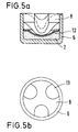
- An anvil 8 is seated on the ignition charge 2 or the cover 12. This anvil 8 is described in more detail in FIG. 5.
- the anvil 8 is a separate component, i.e. not formed in one piece with the sleeve 1 and lies with its outer surface except for openings or recesses completely on the inner surface of the side wall of the capsule 6.
- the anvil 8 is supported in the longitudinal direction of the sleeve 1 on the one hand on the top of the ignition bell 4 and on the other hand on the ignition charge 2.
- the openings in the anvil 8 are arranged in such a way that the fumes can reach the ignition channels 11.
- the ignition bell 4 is provided with an extension 9 in the region of the side wall of the capsule 6.
- Fig. 3 shows an embodiment in which the extension 9 in Cross-section is wedge-shaped or conical.
- the greatest depth of the extension 9 - viewed in the radial direction - is provided at the top of the ignition bell 4.
- the top side means the end face of the ignition bell 4, into which the ignition channels 11 open.
- the extension 9 represents a circumferential undercut of the ignition bell 4, which acts as a radial escape space, free space, extension space or undercut for the side wall of the capsule 6 and thus also for the anvil 8.
- the extension 9 is set back somewhat axially towards the bottom of the capsule 6, so that a stop 10 for the front free end of the cylindrical side wall of the capsule 6 is formed between the extension 9 and the top of the ignition bell 4.
- the stop 10 serves as a guide for the free end of the side wall and as a flow protection in the initial phase of the ignition, so that it is ensured that the pressure in the extension 9 is always less than the pressure in the capsule 6 and thus a proper expansion of the side wall is possible.
- the extension 9 extends over almost half the axial length of the side wall of the capsule 6.
- Fig. 5 shows in section and in plan view a known primer.
- the primer is identical to that shown in FIG. 3.
- the openings 13 in the anvil 8 can be seen, through which the ignition clouds reach the ignition channels 11 (see FIG. 3).
- FIG. 4 is a longitudinal section of the rear end of a cartridge case according to the invention after ignition of the primer shown.
- a firing pin 5 has pressed the capsule bottom of the capsule 6 and remains in this position in the case of a rigid, firmly connected firing pin 5. This is the case in unlocked, mass-locked weapons.
- the ignition charge 2 arranged between the capsule bottom and the anvil 8 was ignited by the impact of the firing pin 5.
- the deformation of the capsule base by the firing pin 5 causes the free end of the side wall of the capsule 6 to be pulled from the top of the ignition bell 4 or the stop 10 in the direction of the capsule base. The end can thus move into extension 9.
- the anvil 8, which is severely deformed by the firing pin 5 or the capsule base, can thereby expand radially, as a result of which its height is reduced in the longitudinal direction and its region opposite the firing pin 5 can, so to speak, move forward.
- In the capsule base in the area of reference number 7 ', there are no such high loads that would lead to a breakage of the capsule base. This ensures gas tightness in the direction of the weapon breech.
- pressure peaks of up to approximately 2,000 bar occur with pollutant-free and gas-rich ignition charges, while pressure peaks of up to approximately 1,000 bar occur with pollutant-containing ignition charges.
Landscapes
- Engineering & Computer Science (AREA)
- General Engineering & Computer Science (AREA)
- Air Bags (AREA)
- Furnace Charging Or Discharging (AREA)
- Portable Nailing Machines And Staplers (AREA)
Abstract
Description
- Die Erfindung betrifft eine Patronenhülse, insbesondere zum Schießen in Handfeuerwaffen, nach dem Oberbegriff des Anspruchs 1.
- Zur Zündung einer Treibladung in einer Patrone ist es bekannt, Anzündhütchen zu verwenden. In den Figuren 1 und 2 ist jeweils im Schnitt das hintere Ende einer Patronenhülse nach dem Stand der Technik mit eingesetztem Anzündhütchen vor (Fig. 1) und nach der Zündung (Fig. 2) gezeigt.
- Eine zylindrische Hülse 1 ist an ihrer hinteren Stirnseite mit einer als zylindrische Ausnehmung ausgebildeten Zündglocke 4 versehen. In die Oberseite der Zündglocke 4 münden Zündkanäle 11, die mit einer nicht gezeigten Treibladung im Inneren der Hülse 1 in Verbindung stehen. In die Zündglocke 4 ist ein Anzündhütchen bündig eingesetzt. Das Anzündhütchen besteht aus einer napfförmigen Kapsel 6 mit einem Kapselboden und einer zylindrischen Seitenwand. Im Inneren der Kapsel 6 ist auf dem Kapselboden eine Anzündladung 2 aufgepreßt. Oberhalb der Anzündladung 2 befindet sich ein Amboß 8 mit Durchbrechungen für die Anzündschwaden. Über eine Ringvernietung 3 ist das Anzündhütchen in der Hülse 1 verankert.
- Trifft der Schlagbolzen 5 einer Waffe auf den Kapselboden (siehe Fig. 2), so verformt sich dieser. Dabei wird die Anzündladung 2 zwischen Kapselboden und Amboß 8 schlagartig komprimiert, wodurch sich diese entzündet. Die Anzündschwaden gelangen über die Durchbrechungen im Amboß 8 zu den Zündkanälen 11 und von dort aus zu der nicht gezeigten Treibladung und zünden diese an.
- Insbesondere Patronenhülsen, die in Handfeuerwaffen verschossen werden, müssen eine Gasdichtigkeit in Richtung Waffenverschluß aufweisen, um eine Gefährdung des Schützen oder eine Waffenbeschädigung sicher zu verhindern. Besonders schadstofffreie Anzündhütchen sind gasreicher als die bisherigen partikel- und zum Teil schadstoffhaltigen. Dadurch ergeben sich bei der Schußentwicklung im Bereich der Zündglocke wesentlich höhere Gasdrücke mit einem sehr kurzzeitigen Druckanstieg. Hierdurch kann es zum Gasaustritt im Bereich des Anzündhütchens kommen, was besonders in unverriegelten Waffen mit Massenverschluß und starren fest verbundenen Schlagbolzen zu beobachten ist.
- In Fig. 2 ist dieser Gasaustritt beispielhaft angedeutet. Das Material des Kapselbodens wird im kritischen Bereich 7, zwischen dem fixierten Amboß 8 des Anzündhütchens und dem Schlagbolzen 5, der durch seine starre Verbindung mit dem Verschluß im Moment der Anzündung nicht zurückweichen kann, sehr stark plastisch verformt. Bedingt durch den hohen Gasdruck des schadstofffreien Anzündhütchens kann das Material des Kapselbodens über die Bruchdehnungsgrenze (Einschnürbruch) im Bereich 7 belastet werden, was dann zu einem Gasaustritt in Richtung Waffenverschluß führen kann bzw. zu einer Wanderung des Zündhütchens und damit zu einer Undichtigkeit bzw. einem "Ausbläser".
- Ähnliche Anzündhütchen, wie oben beschrieben, sind z.B. in der DE-OS 20 04 506 oder DE-OS 27 08 525 gezeigt.
- Der Erfindung liegt die Aufgabe zugrunde, eine Patronenhülse, insbesondere zum Schießen in Handfeuerwaffen, zu schaffen, mit der die Gasdichtigkeit in Richtung Waffenverschluß besonders bei gasreichen und schadstofffreien Anzündladungen wesentlich verbessert ist.
- Erfindungsgemäß wird diese Aufgabe dadurch gelöst, daß die Zündglocke im Bereich der Seitenwand der Kapsel mit einer ringförmig umlaufenden Erweiterung versehen ist, so daß der Amboß nach Zündung der Anzündladung und Aufweitung der Kapsel Platz zum ausweichen hat.
- Die erfindungsgemäße Patronenhülse eignet sich nicht nur für Handfeuerwaffen, sondern auch für Maschinenpistolen, Gewehre o.dgl.
- Bei Druckbelastung kann die Seitenwand der Kapsel in die angrenzende Erweiterung ausweichen. Hierdurch ist der Sitz des Amboß aufgehoben, so daß sich dieser in radialer Richtung verformen, d.h. ausweichen kann. Dies hat zur Folge, daß die Spannungen im kritischen Bereich des Kapselbodens so deutlich reduziert werden, daß keine Materialeinschnürungen auftreten und die Verformungen im Material des Kapselbodens innerhalb des Bereichs der plastischen Dehnung bleiben. Ein Gasaustritt in Richtung Waffenverschluß ist dadurch ver-hindert.
- Erfindungsgemäß ist die Erweiterung in dem an die Oberseite der Zündglocke angrenzenden Bereich angeordnet, so daß bei Druckbelastung das dem Kapselboden abgewandte freie Ende der Kapsel in die Erweiterung ausweichen kann.
- Bevorzugt ist die Erweiterung im Querschnitt keilförmig oder konusförmig ausgebildet. Es sind jedoch auch andere Formen möglich, wie z.B. ein Rundprofil, ein Dreiecksprofil oder andere Geometrien. Die größte Tiefe der Erweiterung ist erfindungsgemäß im an die Oberseite der Zündglocke angrenzenden Bereich vorgesehen.
- In bevorzugter Ausführungsform ist zwischen der Erweiterung und der Oberseite der Zündglocke ein in Radialrichtung wirkender Anschlag für das freie Ende der zylindrischen Seitenwand der Kapsel angeordnet.
- Vorteilhafterweise umschließt die Erweiterung nahezu die Hälfte der Länge der Seitenwand.
- Im folgenden wird die Erfindung anhand von Figuren näher erläutert. Es zeigen:
- Fig. 1:
- im Längsschnitt das hintere Ende einer Patronenhülse mit Anzündhütchen vor Anzündung des Zündsatzes nach dem Stand der Technik,
- Fig. 2:
- im Schnitt die Patronenhülse nach Fig. 1 nach Anzündung des Zündsatzes,
- Fig. 3:
- im Schnitt eine erfindungsgemäße Patronenhülse vor der Anzündung des Zündsatzes und
- Fig. 4:
- im Schnitt die Patronenhülse nach Fig. 3 nach der Anzündung des Zündsatzes,
- Fig. 5:
- im Schnitt und in Draufsicht ein Anzündhütchen bzw. Anzündelement gemäß Fig. 3.
- Die Figuren 1 und 2 zeigen den Stand der Technik (siehe Beschreibungseinleitung).
- Fig. 3 zeigt im Schnitt eine erfindungsgemäße Patronenhülse vor der Anzündung des Zündsatzes. Eine zylinderförmige Hülse 1 ist an ihrem bodenseitigen Ende, die zu einem in dieser Figur nicht gezeigten Schlagbolzen gewandt ist, mit einer zylinderförmigen Ausnehmung versehen, die eine Zündglocke 4 bildet. In die Oberseite der Zündglocke 4 münden Zündkanäle 11, die mit einer nicht gezeigten Treibladung im Inneren der Hülse 1 in Verbindung stehen. In die Zündglocke 4 ist ein Anzündhütchen bündig mit der Bodenfläche der Hülse 1 eingepreßt. Über eine zusätzliche Ringvernietung 3 ist das Anzündhütchen fest in der Hülse 1 verankert.
- Das Anzündhütchen bzw. das Anzündelement besteht aus einer napfförmigen Kapsel 6 mit einem Kapselboden und einer zylindrischen Seitenwand. Die Öffnung der Kapsel 6 ist zu den Zündkanälen 11 gewandt.
- Auf dem Kapselboden ist eine Anzündladung 2 aufgepreßt, die mit einer Abdeckung 12 geschützt ist. Die Abdeckung 12 kann z.B. eine Lackbeschichtung oder eine Folie sein.
- Auf der Anzündladung 2 bzw. der Abdeckung 12 sitzt ein Amboß 8 auf. Dieser Amboß 8 wird noch genauer in Fig. 5 beschrieben. Der Amboß 8 ist ein separates Bauteil, d.h. nicht einstückig mit der Hülse 1 ausgebildet und liegt mit seiner Mantelfläche bis auf Durchbrechungen bzw. Ausnehmungen vollständig an der Innenfläche der Seitenwand der Kapsel 6 an. Der Amboß 8 stützt sich in Längsrichtung der Hülse 1 einerseits an der Oberseite der Zündglocke 4 und andererseits an der Anzündladung 2 ab. Die Durchbrechungen im Amboß 8 sind so angeordnet, daß die Anzündschwaden zu den Zündkanälen 11 gelangen können.
- Erfindungsgemäß ist die Zündglocke 4 im Bereich der Seitenwand der Kapsel 6 mit einer Erweiterung 9 versehen. Fig. 3 zeigt eine Ausführungsform, bei der die Erweiterung 9 im Querschnitt keilförmig bzw. konisch ausgebildet ist. Die größte Tiefe der Erweiterung 9 - in radialer Richtung betrachtet - ist dabei an der Oberseite der Zündglocke 4 vorgesehen. Mit Oberseite ist die Stirnfläche der Zündglocke 4 gemeint, in die die Zündkanäle 11 münden.
- Die Erweiterung 9 stellt eine umlaufende Hinterschneidung der Zündglocke 4 dar, die als radialer Ausweichraum, Freiraum, Erweiterungsraum oder Hinterschnitt für die Seitenwand der Kapsel 6 und damit auch für den Amboß 8 wirkt.
- Von der Oberseite der Zündglocke 4 ist die Erweiterung 9 etwas axial in Richtung Boden der Kapsel 6 zurückversetzt, so daß zwischen der Erweiterung 9 und der Oberseite der Zündglocke 4 ein Anschlag 10 für das vordere freie Ende der zylindrischen Seitenwand der Kapsel 6 gebildet ist. Der Anschlag 10 dient zur Führung für das freie Ende der Seitenwand und als Umströmungsschutz in der Anfangsphase der Zündung, so daß gewährleistet ist, daß der Druck in der Erweiterung 9 immer kleiner ist als der Druck in der Kapsel 6 und damit ein einwandfreies Aufweiten der Seitenwand möglich ist. Die Erweiterung 9 erstreckt sich über nahezu die Hälfte der axialen Länge der Seitenwand der Kapsel 6.
- Fig. 5 zeigt im Schnitt und in der Draufsicht ein bekanntes Anzündhütchen. Das Anzündhütchen ist mit dem in Fig. 3 gezeigten identisch. In der Draufsicht sind die Durchbrechungen 13 im Amboß 8 zu erkennen, über welche die Anzündschwaden zu den Zündkanälen 11 (siehe Fig. 3) gelangen.
- In Fig. 4 ist im Längsschnitt das hintere Ende einer erfindungsgemäßen Patronenhülse nach der Anzündung des Zündsatzes gezeigt. Ein Schlagbolzen 5 hat den Kapselboden der Kapsel 6 eingedrückt und bleibt im Falle eines starren, fest verbundenen Schlagbolzen 5 in dieser Stellung stehen. Dies ist in unverriegelten Waffen mit Massenverschluß der Fall.
- Die zwischen Kapselboden und Amboß 8 angeordnete Anzündladung 2 hat sich durch den Aufschlag des Schlagbolzens 5 entzündet. Die Verformung des Kapselbodens durch den Schlagbolzen 5 bewirkt, daß das freie Ende der Seitenwand der Kapsel 6 von der Oberseite der Zündglocke 4 bzw. dem Anschlag 10 in Richtung Kapselboden gezogen wird. Das Ende kann dadurch in die Erweiterung 9 ausweichen. Der Amboß 8, der vom Schlagbolzen 5 bzw. dem Kapselboden stark verformt wird, kann sich dadurch radial ausdehnen, wodurch seine Höhe in Längsrichtung verringert wird und so sein dem Schlagbolzen 5 gegenüber-liegender Bereich sozusagen nach vorne ausweichen kann. Im Kapselboden, im Bereich der Bezugsziffer 7', entstehen so keine derart hohen Belastungen, die zu einem Bruch des Kapselbodens führen würden. Die Gasdichtigkeit in Richtung Waffenverschluß ist dadurch gegeben.
- Es sei noch angemerkt, daß bei schadstofffreien und gasreichen Anzündladungen Druckspitzen bis etwa 2 000 bar auftreten, während bei schadstoffhaltigen Anzündladungen lediglich Druckspitzen bis etwa 1 000 bar auftreten.
Claims (5)
- Patronenhülse, insbesondere zum Schießen in Handfeuerwaffen, mit einer in ihrem Boden als zylindrische Ausnehmung ausgebildeten Zündglocke (4), in deren Oberseite mindestens ein Zündkanal (11) mündet, mit einem in- die Zündglocke (4) bündig eingelassenen Anzündhütchen mit einer napfförmigen Kapsel (6), die aus einem Kapselboden und einer zylindrischen Seitenwand besteht, und mit im Inneren der Kapsel (6) angeordneter Anzündladung (2) und Amboß (8), dadurch gekennzeichnet, daß die Zündglocke (4) im Bereich der Seitenwand der Kapsel (6) mit einer ringförmig umlaufenden Erweiterung (9) versehen ist, so daß der Amboß (8) nach Zündung der Anzündladung (2) und Aufweitung der Kapsel (6) Platz zum ausweichen hat.
- Patronenhülse nach Anspruch 1, dadurch gekennzeichnet, daß die Erweiterung (9) in dem an die Oberseite der Zündglocke (4) angrenzenden Bereich angeordnet ist.
- Patronenhülse nach Anspruch 1 oder 2, dadurch gekennzeichnet, daß die Erweiterung (9) im Querschnitt keilförmig ausgebildet ist und die größte Tiefe der Erweiterung in dem an die Oberseite der Zündglocke (4) angrenzenden Bereich vorgesehen ist.
- Patronenhülse nach einem der Ansprüche 1 bis 3, dadurch gekennzeichnet, daß zwischen der Erweiterung (9) und der Oberseite der Zündglocke (4) ein Anschlag (10) für das Ende der zylindrischen Seitenwand der Kapsel (6) angeordnet ist.
- Patronenhülse nach einem der Ansprüche 1 bis 4, dadurch gekennzeichnet, daß die Erweiterung (9) sich nahezu über die Hälfte der Länge der Seitenwand der Kapsel (6) erstreckt.
Applications Claiming Priority (4)
| Application Number | Priority Date | Filing Date | Title |
|---|---|---|---|
| DE4340998 | 1993-12-01 | ||
| DE4340998 | 1993-12-01 | ||
| DE4341002 | 1993-12-02 | ||
| DE4341002A DE4341002A1 (de) | 1993-12-01 | 1993-12-02 | Patronenhülse |
Publications (2)
| Publication Number | Publication Date |
|---|---|
| EP0656522A1 true EP0656522A1 (de) | 1995-06-07 |
| EP0656522B1 EP0656522B1 (de) | 2000-03-01 |
Family
ID=25931695
Family Applications (1)
| Application Number | Title | Priority Date | Filing Date |
|---|---|---|---|
| EP94118834A Expired - Lifetime EP0656522B1 (de) | 1993-12-01 | 1994-11-30 | Patronenhülse |
Country Status (3)
| Country | Link |
|---|---|
| US (1) | US5481978A (de) |
| EP (1) | EP0656522B1 (de) |
| AT (1) | ATE190132T1 (de) |
Families Citing this family (17)
| Publication number | Priority date | Publication date | Assignee | Title |
|---|---|---|---|---|
| JP3989563B2 (ja) * | 1995-09-22 | 2007-10-10 | ダイセル化学工業株式会社 | エアバッグ用ガス発生器 |
| WO1999040387A1 (en) * | 1998-02-05 | 1999-08-12 | Olin Corporation | Cartridge case |
| US6367389B1 (en) * | 1999-10-25 | 2002-04-09 | Mark A. Westrom | Cartridge for a firearm |
| US6959647B2 (en) * | 1999-10-25 | 2005-11-01 | Mark A. Wistrom | Cartridge for a firearm |
| US6360666B1 (en) * | 2000-06-06 | 2002-03-26 | Alliant Techsystems Inc. | Alignment fixture |
| US7086336B2 (en) * | 2000-09-28 | 2006-08-08 | Superior Ballistics, Inc. | Firearm cartridge and case-less chamber |
| US7210260B1 (en) | 2000-09-28 | 2007-05-01 | Robert B. Smalley, Jr. | Firearm cartridge and case-less chamber |
| US7546805B2 (en) * | 2001-07-17 | 2009-06-16 | Schlumberger Technology Corporation | Detonator |
| US7165496B2 (en) * | 2003-11-06 | 2007-01-23 | Reynolds S Paul | Piston head cartridge for a firearm |
| US7581344B2 (en) * | 2004-12-22 | 2009-09-01 | Armalite, Inc. | Weapon extractor and cartridge |
| US7841279B2 (en) * | 2006-05-24 | 2010-11-30 | Reynolds George L | Delayed extraction and a firearm cartridge case |
| US8424646B2 (en) * | 2006-07-10 | 2013-04-23 | United Technologies Corporation | Interruption tolerant lubrication system |
| US9267772B2 (en) * | 2012-06-27 | 2016-02-23 | Aai Corporation | Ballistic sealing, component retention, and projectile launch control for an ammunition cartridge assembly |
| US20170328689A1 (en) * | 2016-05-11 | 2017-11-16 | U.S. Government As Represented By The Secretary Of The Army | Lightweight Cartridge Case |
| US10976144B1 (en) | 2018-03-05 | 2021-04-13 | Vista Outdoor Operations Llc | High pressure rifle cartridge with primer |
| US12467727B2 (en) * | 2023-01-11 | 2025-11-11 | Sig Sauer, Inc. | Ammunition blank and corresponding bolt |
| US12474148B2 (en) * | 2023-11-22 | 2025-11-18 | Howard D. Kent | Cartridge primer and method of manufacture |
Citations (3)
| Publication number | Priority date | Publication date | Assignee | Title |
|---|---|---|---|---|
| DE73301C (de) * | O. BÖKLEN in Lauffen a. Neckar | Patronenhülse mit nach vorn erweiterter Zündhütchenkammer | ||
| US3306203A (en) * | 1960-04-27 | 1967-02-28 | Schaadt Franz | Threaded percussion primer |
| EP0461095A1 (de) * | 1990-06-06 | 1991-12-11 | Bofors AB | Verbesserungen an Zündern |
Family Cites Families (2)
| Publication number | Priority date | Publication date | Assignee | Title |
|---|---|---|---|---|
| US431601A (en) * | 1890-07-08 | Wilhelm lorenz | ||
| US4173186A (en) * | 1960-07-07 | 1979-11-06 | The United States Of America As Represented By The Secretary Of The Army | Ammunition |
-
1994
- 1994-11-30 AT AT94118834T patent/ATE190132T1/de active
- 1994-11-30 US US08/351,178 patent/US5481978A/en not_active Expired - Lifetime
- 1994-11-30 EP EP94118834A patent/EP0656522B1/de not_active Expired - Lifetime
Patent Citations (3)
| Publication number | Priority date | Publication date | Assignee | Title |
|---|---|---|---|---|
| DE73301C (de) * | O. BÖKLEN in Lauffen a. Neckar | Patronenhülse mit nach vorn erweiterter Zündhütchenkammer | ||
| US3306203A (en) * | 1960-04-27 | 1967-02-28 | Schaadt Franz | Threaded percussion primer |
| EP0461095A1 (de) * | 1990-06-06 | 1991-12-11 | Bofors AB | Verbesserungen an Zündern |
Also Published As
| Publication number | Publication date |
|---|---|
| EP0656522B1 (de) | 2000-03-01 |
| ATE190132T1 (de) | 2000-03-15 |
| US5481978A (en) | 1996-01-09 |
Similar Documents
| Publication | Publication Date | Title |
|---|---|---|
| EP0656522B1 (de) | Patronenhülse | |
| DE69026714T2 (de) | Kollabierbarer bodenpfropfen | |
| DE2914049C2 (de) | Patrone | |
| DE2832879A1 (de) | Treibladungsanzuender | |
| DE2437535C3 (de) | Ausstoßbarer Nebeltopf für hochbeanspruchte Geschosse | |
| DE8812000U1 (de) | Granatengeschoß | |
| DE60104950T2 (de) | Anzündrohr für artilleriemunition | |
| DE3918005C2 (de) | ||
| DE19725476A1 (de) | Gasgenerator | |
| DE3149346A1 (de) | Aufschlagzuender | |
| DE69113112T2 (de) | Patronierte Munition in Teleskopanordnung. | |
| DE2553717A1 (de) | Zuendvorrichtung | |
| DE19738937C2 (de) | Patronierte Munition | |
| DE3815738A1 (de) | Patrone mit flintenlaufgeschoss | |
| EP0511229B1 (de) | Patrone, insbesondere granatpatrone | |
| DE4400545A1 (de) | Anordnung in einem Rauchladungs-Behälter | |
| EP1688694B1 (de) | Mechanisches Initiiersystem für hülsenlose Munition | |
| DE19751932C2 (de) | Gasgenerator zur Reichweitensteigerung eines Geschosses und Geschoß mit Gasgenerator | |
| DE1578208A1 (de) | Geschosspatrone mit Zuendkapsel | |
| EP2531800B1 (de) | Dichtungsring und treibladungslager | |
| DE2446832C2 (de) | Zündvorrichtung für Werferrohre zur Zündung der Antriebsladung eines Projektils | |
| DE4341002A1 (de) | Patronenhülse | |
| WO1998057829A1 (de) | Gasgenerator | |
| DE3521184C2 (de) | ||
| DE3727365C2 (de) |
Legal Events
| Date | Code | Title | Description |
|---|---|---|---|
| PUAI | Public reference made under article 153(3) epc to a published international application that has entered the european phase |
Free format text: ORIGINAL CODE: 0009012 |
|
| AK | Designated contracting states |
Kind code of ref document: A1 Designated state(s): AT DE FR GB IT PT |
|
| 17P | Request for examination filed |
Effective date: 19951129 |
|
| RAP1 | Party data changed (applicant data changed or rights of an application transferred) |
Owner name: DYNAMIT NOBEL GMBH EXPLOSIVSTOFF- UND SYSTEMTECHNI |
|
| 17Q | First examination report despatched |
Effective date: 19970609 |
|
| GRAG | Despatch of communication of intention to grant |
Free format text: ORIGINAL CODE: EPIDOS AGRA |
|
| GRAG | Despatch of communication of intention to grant |
Free format text: ORIGINAL CODE: EPIDOS AGRA |
|
| GRAH | Despatch of communication of intention to grant a patent |
Free format text: ORIGINAL CODE: EPIDOS IGRA |
|
| GRAH | Despatch of communication of intention to grant a patent |
Free format text: ORIGINAL CODE: EPIDOS IGRA |
|
| ITF | It: translation for a ep patent filed | ||
| GRAA | (expected) grant |
Free format text: ORIGINAL CODE: 0009210 |
|
| AK | Designated contracting states |
Kind code of ref document: B1 Designated state(s): AT DE FR GB IT PT |
|
| PG25 | Lapsed in a contracting state [announced via postgrant information from national office to epo] |
Ref country code: GB Free format text: LAPSE BECAUSE OF FAILURE TO SUBMIT A TRANSLATION OF THE DESCRIPTION OR TO PAY THE FEE WITHIN THE PRESCRIBED TIME-LIMIT Effective date: 20000301 Ref country code: FR Free format text: LAPSE BECAUSE OF FAILURE TO SUBMIT A TRANSLATION OF THE DESCRIPTION OR TO PAY THE FEE WITHIN THE PRESCRIBED TIME-LIMIT Effective date: 20000301 |
|
| REF | Corresponds to: |
Ref document number: 190132 Country of ref document: AT Date of ref document: 20000315 Kind code of ref document: T |
|
| REF | Corresponds to: |
Ref document number: 59409165 Country of ref document: DE Date of ref document: 20000406 |
|
| PG25 | Lapsed in a contracting state [announced via postgrant information from national office to epo] |
Ref country code: PT Free format text: LAPSE BECAUSE OF FAILURE TO SUBMIT A TRANSLATION OF THE DESCRIPTION OR TO PAY THE FEE WITHIN THE PRESCRIBED TIME-LIMIT Effective date: 20000601 |
|
| EN | Fr: translation not filed | ||
| GBV | Gb: ep patent (uk) treated as always having been void in accordance with gb section 77(7)/1977 [no translation filed] |
Effective date: 20000301 |
|
| PLBE | No opposition filed within time limit |
Free format text: ORIGINAL CODE: 0009261 |
|
| STAA | Information on the status of an ep patent application or granted ep patent |
Free format text: STATUS: NO OPPOSITION FILED WITHIN TIME LIMIT |
|
| 26N | No opposition filed | ||
| PGFP | Annual fee paid to national office [announced via postgrant information from national office to epo] |
Ref country code: AT Payment date: 20131113 Year of fee payment: 20 |
|
| PGFP | Annual fee paid to national office [announced via postgrant information from national office to epo] |
Ref country code: IT Payment date: 20131128 Year of fee payment: 20 |
|
| PGFP | Annual fee paid to national office [announced via postgrant information from national office to epo] |
Ref country code: DE Payment date: 20140131 Year of fee payment: 20 |
|
| REG | Reference to a national code |
Ref country code: DE Ref legal event code: R071 Ref document number: 59409165 Country of ref document: DE |
|
| REG | Reference to a national code |
Ref country code: AT Ref legal event code: MK07 Ref document number: 190132 Country of ref document: AT Kind code of ref document: T Effective date: 20141130 |