EP0656522A1 - Douille pour cartouche - Google Patents
Douille pour cartouche Download PDFInfo
- Publication number
- EP0656522A1 EP0656522A1 EP94118834A EP94118834A EP0656522A1 EP 0656522 A1 EP0656522 A1 EP 0656522A1 EP 94118834 A EP94118834 A EP 94118834A EP 94118834 A EP94118834 A EP 94118834A EP 0656522 A1 EP0656522 A1 EP 0656522A1
- Authority
- EP
- European Patent Office
- Prior art keywords
- capsule
- ignition
- extension
- side wall
- bell
- Prior art date
- Legal status (The legal status is an assumption and is not a legal conclusion. Google has not performed a legal analysis and makes no representation as to the accuracy of the status listed.)
- Granted
Links
Images


Classifications
-
- F—MECHANICAL ENGINEERING; LIGHTING; HEATING; WEAPONS; BLASTING
- F42—AMMUNITION; BLASTING
- F42B—EXPLOSIVE CHARGES, e.g. FOR BLASTING, FIREWORKS, AMMUNITION
- F42B5/00—Cartridge ammunition, e.g. separately-loaded propellant charges
- F42B5/26—Cartridge cases
- F42B5/36—Cartridge cases modified for housing an integral firing-cap
-
- F—MECHANICAL ENGINEERING; LIGHTING; HEATING; WEAPONS; BLASTING
- F42—AMMUNITION; BLASTING
- F42C—AMMUNITION FUZES; ARMING OR SAFETY MEANS THEREFOR
- F42C19/00—Details of fuzes
- F42C19/08—Primers; Detonators
- F42C19/10—Percussion caps
Definitions
- the invention relates to a cartridge case, in particular for firing in small arms, according to the preamble of claim 1.
- FIGS. 1 and 2 each show in section the rear end of a cartridge case according to the prior art with the primer cap inserted before (FIG. 1) and after the ignition (FIG. 2).
- a cylindrical sleeve 1 is provided on its rear end face with a ignition bell 4 designed as a cylindrical recess.
- An ignition cap is inserted flush into the ignition bell 4.
- the primer consists of a cup-shaped capsule 6 with a capsule bottom and a cylindrical side wall.
- An ignition charge 2 is pressed onto the capsule base inside the capsule 6. Above the ignition charge 2 there is an anvil 8 with openings for the ignition vapor.
- the primer cap is anchored in the sleeve 1 by means of ring riveting 3.
- the firing pin 5 of a weapon hits the capsule base (see FIG. 2), it deforms.
- the ignition charge 2 is suddenly compressed between the capsule bottom and anvil 8, causing it to ignite.
- the ignition fumes pass through the openings in the anvil 8 to the ignition channels 11 and from there to the propellant charge, not shown, and ignite it.
- Cartridge casings in particular, which are fired in small arms, must be gas-tight in the direction of the weapon breech in order to reliably prevent the shooter from being endangered or from being damaged.
- Primer caps that are particularly free of pollutants are more gas-rich than the previous ones that contain particles and some contain pollutants. This results in significantly higher gas pressures with a very short pressure increase in the development of the shot in the area of the ignition bell. This can lead to gas leakage in the area of the primer, which can be observed particularly in unlocked weapons with a mass lock and rigid firing pins.
- This gas outlet is indicated by way of example in FIG. 2.
- the material of the capsule bottom is deformed very strongly plastically in the critical area 7, between the fixed anvil 8 of the primer cap and the firing pin 5, which cannot move back due to its rigid connection to the closure at the moment of ignition. Due to the high gas pressure of the pollutant-free primer cap, the material of the capsule base can be stressed beyond the limit of elongation at break (constriction fracture) in area 7, which can then lead to gas escaping in the direction of the weapon breech or to migration of the primer cap and thus to a leak or one "Blower".
- the invention has for its object to provide a cartridge case, in particular for firing in small arms, with which the gas tightness in the direction of the weapon breech is significantly improved, especially with gas-rich and pollutant-free igniter charges.
- this object is achieved in that the ignition bell is provided in the region of the side wall of the capsule with an annular circumferential extension, so that the anvil has space to escape after the ignition charge has been fired and the capsule expanded.
- the cartridge case according to the invention is not only suitable for small arms, but also for submachine guns, rifles or the like.
- the side wall of the capsule When pressure is applied, the side wall of the capsule can move into the adjacent extension. This removes the anvil's seat so that it deforms in the radial direction, i.e. can dodge. The consequence of this is that the stresses in the critical area of the capsule base are reduced so significantly that no material constrictions occur and the deformations in the material of the capsule base remain within the range of the plastic expansion. This prevents gas escaping in the direction of the weapon lock.
- the extension is arranged in the area adjacent to the upper side of the ignition bell, so that the free end of the capsule facing away from the capsule base can deflect into the extension under pressure.
- the cross section is preferably wedge-shaped or conical. However, other shapes are also possible, such as a round profile, a triangular profile or other geometries. According to the invention, the greatest depth of the extension is provided in the area adjacent to the top of the ignition bell.
- a stop acting in the radial direction for the free end of the cylindrical side wall of the capsule is arranged between the extension and the top of the ignition bell.
- the extension advantageously encloses almost half the length of the side wall.
- FIGS 1 and 2 show the prior art (see introduction to the description).
- Fig. 3 shows a section of a cartridge case according to the invention before the ignition of the primer.
- a cylindrical sleeve 1 is at its bottom end that leads to one in this Figure not shown firing pin is facing, provided with a cylindrical recess which forms an ignition bell 4.
- An ignition cap is pressed into the ignition bell 4 flush with the bottom surface of the sleeve 1.
- the primer cap is firmly anchored in the sleeve 1 via an additional ring rivet 3.
- the primer or igniter consists of a cup-shaped capsule 6 with a capsule bottom and a cylindrical side wall. The opening of the capsule 6 faces the ignition channels 11.
- An ignition charge 2 which is protected by a cover 12 is pressed onto the base of the capsule.
- the cover 12 can e.g. a lacquer coating or a film.
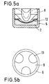
- An anvil 8 is seated on the ignition charge 2 or the cover 12. This anvil 8 is described in more detail in FIG. 5.
- the anvil 8 is a separate component, i.e. not formed in one piece with the sleeve 1 and lies with its outer surface except for openings or recesses completely on the inner surface of the side wall of the capsule 6.
- the anvil 8 is supported in the longitudinal direction of the sleeve 1 on the one hand on the top of the ignition bell 4 and on the other hand on the ignition charge 2.
- the openings in the anvil 8 are arranged in such a way that the fumes can reach the ignition channels 11.
- the ignition bell 4 is provided with an extension 9 in the region of the side wall of the capsule 6.
- Fig. 3 shows an embodiment in which the extension 9 in Cross-section is wedge-shaped or conical.
- the greatest depth of the extension 9 - viewed in the radial direction - is provided at the top of the ignition bell 4.
- the top side means the end face of the ignition bell 4, into which the ignition channels 11 open.
- the extension 9 represents a circumferential undercut of the ignition bell 4, which acts as a radial escape space, free space, extension space or undercut for the side wall of the capsule 6 and thus also for the anvil 8.
- the extension 9 is set back somewhat axially towards the bottom of the capsule 6, so that a stop 10 for the front free end of the cylindrical side wall of the capsule 6 is formed between the extension 9 and the top of the ignition bell 4.
- the stop 10 serves as a guide for the free end of the side wall and as a flow protection in the initial phase of the ignition, so that it is ensured that the pressure in the extension 9 is always less than the pressure in the capsule 6 and thus a proper expansion of the side wall is possible.
- the extension 9 extends over almost half the axial length of the side wall of the capsule 6.
- Fig. 5 shows in section and in plan view a known primer.
- the primer is identical to that shown in FIG. 3.
- the openings 13 in the anvil 8 can be seen, through which the ignition clouds reach the ignition channels 11 (see FIG. 3).
- FIG. 4 is a longitudinal section of the rear end of a cartridge case according to the invention after ignition of the primer shown.
- a firing pin 5 has pressed the capsule bottom of the capsule 6 and remains in this position in the case of a rigid, firmly connected firing pin 5. This is the case in unlocked, mass-locked weapons.
- the ignition charge 2 arranged between the capsule bottom and the anvil 8 was ignited by the impact of the firing pin 5.
- the deformation of the capsule base by the firing pin 5 causes the free end of the side wall of the capsule 6 to be pulled from the top of the ignition bell 4 or the stop 10 in the direction of the capsule base. The end can thus move into extension 9.
- the anvil 8, which is severely deformed by the firing pin 5 or the capsule base, can thereby expand radially, as a result of which its height is reduced in the longitudinal direction and its region opposite the firing pin 5 can, so to speak, move forward.
- In the capsule base in the area of reference number 7 ', there are no such high loads that would lead to a breakage of the capsule base. This ensures gas tightness in the direction of the weapon breech.
- pressure peaks of up to approximately 2,000 bar occur with pollutant-free and gas-rich ignition charges, while pressure peaks of up to approximately 1,000 bar occur with pollutant-containing ignition charges.
Landscapes
- Engineering & Computer Science (AREA)
- General Engineering & Computer Science (AREA)
- Air Bags (AREA)
- Furnace Charging Or Discharging (AREA)
- Portable Nailing Machines And Staplers (AREA)
Applications Claiming Priority (4)
| Application Number | Priority Date | Filing Date | Title |
|---|---|---|---|
| DE4340998 | 1993-12-01 | ||
| DE4340998 | 1993-12-01 | ||
| DE4341002 | 1993-12-02 | ||
| DE4341002A DE4341002A1 (de) | 1993-12-01 | 1993-12-02 | Patronenhülse |
Publications (2)
| Publication Number | Publication Date |
|---|---|
| EP0656522A1 true EP0656522A1 (fr) | 1995-06-07 |
| EP0656522B1 EP0656522B1 (fr) | 2000-03-01 |
Family
ID=25931695
Family Applications (1)
| Application Number | Title | Priority Date | Filing Date |
|---|---|---|---|
| EP94118834A Expired - Lifetime EP0656522B1 (fr) | 1993-12-01 | 1994-11-30 | Douille pour cartouche |
Country Status (3)
| Country | Link |
|---|---|
| US (1) | US5481978A (fr) |
| EP (1) | EP0656522B1 (fr) |
| AT (1) | ATE190132T1 (fr) |
Families Citing this family (15)
| Publication number | Priority date | Publication date | Assignee | Title |
|---|---|---|---|---|
| JP3989563B2 (ja) * | 1995-09-22 | 2007-10-10 | ダイセル化学工業株式会社 | エアバッグ用ガス発生器 |
| AU2574899A (en) * | 1998-02-05 | 1999-08-23 | Olin Corporation | Cartridge case |
| US6959647B2 (en) * | 1999-10-25 | 2005-11-01 | Mark A. Wistrom | Cartridge for a firearm |
| US6367389B1 (en) * | 1999-10-25 | 2002-04-09 | Mark A. Westrom | Cartridge for a firearm |
| US6360666B1 (en) * | 2000-06-06 | 2002-03-26 | Alliant Techsystems Inc. | Alignment fixture |
| US7086336B2 (en) * | 2000-09-28 | 2006-08-08 | Superior Ballistics, Inc. | Firearm cartridge and case-less chamber |
| US7210260B1 (en) | 2000-09-28 | 2007-05-01 | Robert B. Smalley, Jr. | Firearm cartridge and case-less chamber |
| US7546805B2 (en) * | 2001-07-17 | 2009-06-16 | Schlumberger Technology Corporation | Detonator |
| US7165496B2 (en) * | 2003-11-06 | 2007-01-23 | Reynolds S Paul | Piston head cartridge for a firearm |
| US7581344B2 (en) * | 2004-12-22 | 2009-09-01 | Armalite, Inc. | Weapon extractor and cartridge |
| US7841279B2 (en) * | 2006-05-24 | 2010-11-30 | Reynolds George L | Delayed extraction and a firearm cartridge case |
| US8424646B2 (en) * | 2006-07-10 | 2013-04-23 | United Technologies Corporation | Interruption tolerant lubrication system |
| US9267772B2 (en) * | 2012-06-27 | 2016-02-23 | Aai Corporation | Ballistic sealing, component retention, and projectile launch control for an ammunition cartridge assembly |
| US20170328689A1 (en) * | 2016-05-11 | 2017-11-16 | U.S. Government As Represented By The Secretary Of The Army | Lightweight Cartridge Case |
| US10976144B1 (en) | 2018-03-05 | 2021-04-13 | Vista Outdoor Operations Llc | High pressure rifle cartridge with primer |
Citations (3)
| Publication number | Priority date | Publication date | Assignee | Title |
|---|---|---|---|---|
| DE73301C (de) * | O. BÖKLEN in Lauffen a. Neckar | Patronenhülse mit nach vorn erweiterter Zündhütchenkammer | ||
| US3306203A (en) * | 1960-04-27 | 1967-02-28 | Schaadt Franz | Threaded percussion primer |
| EP0461095A1 (fr) * | 1990-06-06 | 1991-12-11 | Bofors AB | Améliorations relatives aux amorces pour charges propulsives |
Family Cites Families (2)
| Publication number | Priority date | Publication date | Assignee | Title |
|---|---|---|---|---|
| US431601A (en) * | 1890-07-08 | Wilhelm lorenz | ||
| US4173186A (en) * | 1960-07-07 | 1979-11-06 | The United States Of America As Represented By The Secretary Of The Army | Ammunition |
-
1994
- 1994-11-30 US US08/351,178 patent/US5481978A/en not_active Expired - Lifetime
- 1994-11-30 EP EP94118834A patent/EP0656522B1/fr not_active Expired - Lifetime
- 1994-11-30 AT AT94118834T patent/ATE190132T1/de active
Patent Citations (3)
| Publication number | Priority date | Publication date | Assignee | Title |
|---|---|---|---|---|
| DE73301C (de) * | O. BÖKLEN in Lauffen a. Neckar | Patronenhülse mit nach vorn erweiterter Zündhütchenkammer | ||
| US3306203A (en) * | 1960-04-27 | 1967-02-28 | Schaadt Franz | Threaded percussion primer |
| EP0461095A1 (fr) * | 1990-06-06 | 1991-12-11 | Bofors AB | Améliorations relatives aux amorces pour charges propulsives |
Also Published As
| Publication number | Publication date |
|---|---|
| US5481978A (en) | 1996-01-09 |
| ATE190132T1 (de) | 2000-03-15 |
| EP0656522B1 (fr) | 2000-03-01 |
Similar Documents
| Publication | Publication Date | Title |
|---|---|---|
| DE2914049C2 (de) | Patrone | |
| EP0656522B1 (fr) | Douille pour cartouche | |
| DE2832879A1 (de) | Treibladungsanzuender | |
| DE2437535C3 (de) | Ausstoßbarer Nebeltopf für hochbeanspruchte Geschosse | |
| DE2826497A1 (de) | Treibspiegelgeschoss mit pyrotechnischem satz | |
| DE60104950T2 (de) | Anzündrohr für artilleriemunition | |
| DE3918005C2 (fr) | ||
| DE19725476A1 (de) | Gasgenerator | |
| EP1688694B1 (fr) | Système mécanique d'initiation pour munitions sans douille | |
| DE3149346A1 (de) | Aufschlagzuender | |
| DE2553717A1 (de) | Zuendvorrichtung | |
| EP0511229B1 (fr) | Cartouche, en particulier cartouche-grenade | |
| DE19738937C2 (de) | Patronierte Munition | |
| DE3815738A1 (de) | Patrone mit flintenlaufgeschoss | |
| DE4400545A1 (de) | Anordnung in einem Rauchladungs-Behälter | |
| DE19751932C2 (de) | Gasgenerator zur Reichweitensteigerung eines Geschosses und Geschoß mit Gasgenerator | |
| EP2531800B1 (fr) | Bague d'étanchéité et magasin de charge propulsive | |
| DE2446832C2 (de) | Zündvorrichtung für Werferrohre zur Zündung der Antriebsladung eines Projektils | |
| DE4341002A1 (de) | Patronenhülse | |
| DE1578208A1 (de) | Geschosspatrone mit Zuendkapsel | |
| WO1998057829A1 (fr) | Generateur de gaz | |
| DE3521184C2 (fr) | ||
| DE3727365C2 (fr) | ||
| DE2609391C2 (de) | Trägergeschoß zum Verschießen von Sekundärgeschossen | |
| CH693543A5 (de) | Patronierte Munition. |
Legal Events
| Date | Code | Title | Description |
|---|---|---|---|
| PUAI | Public reference made under article 153(3) epc to a published international application that has entered the european phase |
Free format text: ORIGINAL CODE: 0009012 |
|
| AK | Designated contracting states |
Kind code of ref document: A1 Designated state(s): AT DE FR GB IT PT |
|
| 17P | Request for examination filed |
Effective date: 19951129 |
|
| RAP1 | Party data changed (applicant data changed or rights of an application transferred) |
Owner name: DYNAMIT NOBEL GMBH EXPLOSIVSTOFF- UND SYSTEMTECHNI |
|
| 17Q | First examination report despatched |
Effective date: 19970609 |
|
| GRAG | Despatch of communication of intention to grant |
Free format text: ORIGINAL CODE: EPIDOS AGRA |
|
| GRAG | Despatch of communication of intention to grant |
Free format text: ORIGINAL CODE: EPIDOS AGRA |
|
| GRAH | Despatch of communication of intention to grant a patent |
Free format text: ORIGINAL CODE: EPIDOS IGRA |
|
| GRAH | Despatch of communication of intention to grant a patent |
Free format text: ORIGINAL CODE: EPIDOS IGRA |
|
| ITF | It: translation for a ep patent filed |
Owner name: BARZANO' E ZANARDO ROMA S.P.A. |
|
| GRAA | (expected) grant |
Free format text: ORIGINAL CODE: 0009210 |
|
| AK | Designated contracting states |
Kind code of ref document: B1 Designated state(s): AT DE FR GB IT PT |
|
| PG25 | Lapsed in a contracting state [announced via postgrant information from national office to epo] |
Ref country code: GB Free format text: LAPSE BECAUSE OF FAILURE TO SUBMIT A TRANSLATION OF THE DESCRIPTION OR TO PAY THE FEE WITHIN THE PRESCRIBED TIME-LIMIT Effective date: 20000301 Ref country code: FR Free format text: LAPSE BECAUSE OF FAILURE TO SUBMIT A TRANSLATION OF THE DESCRIPTION OR TO PAY THE FEE WITHIN THE PRESCRIBED TIME-LIMIT Effective date: 20000301 |
|
| REF | Corresponds to: |
Ref document number: 190132 Country of ref document: AT Date of ref document: 20000315 Kind code of ref document: T |
|
| REF | Corresponds to: |
Ref document number: 59409165 Country of ref document: DE Date of ref document: 20000406 |
|
| PG25 | Lapsed in a contracting state [announced via postgrant information from national office to epo] |
Ref country code: PT Free format text: LAPSE BECAUSE OF FAILURE TO SUBMIT A TRANSLATION OF THE DESCRIPTION OR TO PAY THE FEE WITHIN THE PRESCRIBED TIME-LIMIT Effective date: 20000601 |
|
| EN | Fr: translation not filed | ||
| GBV | Gb: ep patent (uk) treated as always having been void in accordance with gb section 77(7)/1977 [no translation filed] |
Effective date: 20000301 |
|
| PLBE | No opposition filed within time limit |
Free format text: ORIGINAL CODE: 0009261 |
|
| STAA | Information on the status of an ep patent application or granted ep patent |
Free format text: STATUS: NO OPPOSITION FILED WITHIN TIME LIMIT |
|
| 26N | No opposition filed | ||
| PGFP | Annual fee paid to national office [announced via postgrant information from national office to epo] |
Ref country code: AT Payment date: 20131113 Year of fee payment: 20 |
|
| PGFP | Annual fee paid to national office [announced via postgrant information from national office to epo] |
Ref country code: IT Payment date: 20131128 Year of fee payment: 20 |
|
| PGFP | Annual fee paid to national office [announced via postgrant information from national office to epo] |
Ref country code: DE Payment date: 20140131 Year of fee payment: 20 |
|
| REG | Reference to a national code |
Ref country code: DE Ref legal event code: R071 Ref document number: 59409165 Country of ref document: DE |
|
| REG | Reference to a national code |
Ref country code: AT Ref legal event code: MK07 Ref document number: 190132 Country of ref document: AT Kind code of ref document: T Effective date: 20141130 |