EP0654332A1 - Scie à panneaux - Google Patents
Scie à panneaux Download PDFInfo
- Publication number
- EP0654332A1 EP0654332A1 EP93120071A EP93120071A EP0654332A1 EP 0654332 A1 EP0654332 A1 EP 0654332A1 EP 93120071 A EP93120071 A EP 93120071A EP 93120071 A EP93120071 A EP 93120071A EP 0654332 A1 EP0654332 A1 EP 0654332A1
- Authority
- EP
- European Patent Office
- Prior art keywords
- workpiece
- saw
- panel
- plate
- separating means
- Prior art date
- Legal status (The legal status is an assumption and is not a legal conclusion. Google has not performed a legal analysis and makes no representation as to the accuracy of the status listed.)
- Granted
Links
Images


Classifications
-
- B—PERFORMING OPERATIONS; TRANSPORTING
- B27—WORKING OR PRESERVING WOOD OR SIMILAR MATERIAL; NAILING OR STAPLING MACHINES IN GENERAL
- B27B—SAWS FOR WOOD OR SIMILAR MATERIAL; COMPONENTS OR ACCESSORIES THEREFOR
- B27B31/00—Arrangements for conveying, loading, turning, adjusting, or discharging the log or timber, specially designed for saw mills or sawing machines
- B27B31/08—Discharging equipment
-
- B—PERFORMING OPERATIONS; TRANSPORTING
- B27—WORKING OR PRESERVING WOOD OR SIMILAR MATERIAL; NAILING OR STAPLING MACHINES IN GENERAL
- B27B—SAWS FOR WOOD OR SIMILAR MATERIAL; COMPONENTS OR ACCESSORIES THEREFOR
- B27B31/00—Arrangements for conveying, loading, turning, adjusting, or discharging the log or timber, specially designed for saw mills or sawing machines
- B27B31/003—Arrangements for conveying, loading, turning, adjusting, or discharging the log or timber, specially designed for saw mills or sawing machines with rollers
Definitions
- the invention relates to a plate dividing system for the color division of plate-shaped workpieces or workpiece stacks.
- Known plate sizing systems have a saw with a saw unit which can be moved along a cutting line and which can be fed with plate-shaped workpiece strips or stacks lying next to one another on a workpiece support table by at least two workpiece slides which can be moved independently of one another.
- the panel blanks which are separated from the workpiece strips by a separating cut of the saw, are moved on a workpiece removal table following the saw when the workpiece strips are inserted for the next separating cut.
- the two workpiece slides cover different travels when inserting the workpiece strips into the saw according to the distribution plan, the closely spaced, cut panel cuts are shifted and rubbed to different degrees to each other.
- the divided panel blanks can hook up behind one another and possibly twist behind the saw, so that an orderly further transport of the panel blanks is no longer possible.
- the invention has for its object to provide a new plate sizing system for the color division of plate-shaped workpieces, in which a trouble-free further transport of the finished plate blanks is ensured behind the saw.
- the workpiece removal table arranged downstream of the saw has a separating device, the separating means of which can be activated as required, that is to say can be moved from a rest position into a working position and back.
- the separating device advantageously has a plurality of crossways for the transport direction of the panel blanks, separating means arranged next to one another, which can be brought into their working position independently of one another.
- the position of the first separating means in its working position, seen from an edge of the plate removal table, can be determined in accordance with the dividing line between the plate cuts covering the different displacement paths.
- the individual release agents can therefore be activated depending on the position of this separation line.
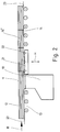
- the plate dividing system shown in FIG. 1 comprises a saw 10 with a saw unit, not shown in detail, which preferably moves under a table and which defines a cutting line 11.
- a workpiece support table 13 with a low-friction contact surface is provided in the insertion direction E in front of the saw 10, which is designed, for example, as a roller table - as indicated in FIG. 2 - or as an air cushion table.
- a workpiece removal table 14 is arranged, which also has a low-friction contact surface and z. B. can be designed as a roller table ( Figure 2).
- a stop ruler 15 is provided which extends beyond the cutting line 11 along the workpiece removal table 14 and serves there for the lateral guidance of the separated panel blanks or panel blank stacks 16 .
- two workpiece slides 17, 18 which can be moved independently of one another are provided and are only indicated as arrows.
- a separating device 20 which comprises a plurality of roller rails 21 serving as separating means.
- Each of these roller rails 21 - as indicated in FIG. 2 by the double arrow H - can be raised and lowered on the workpiece removal table 14 and has a plurality of inclined rollers 22 which extend in the direction of insertion E or in the transport direction of the plate blank stacks 16, 16 'are arranged in series one behind the other.
- their axes of rotation 24, which are arranged parallel to the table plane 23, form an angle different from 90 ° with the insertion or transport direction E, so that the conveying direction caused by the inclined rollers 22 is thus directed away from the stop ruler 15.
- the individual plate blank stacks 16 ′ acted upon by the separating device 20 are thus displaced by the distance a from the plate blank stacks 16 abutting the stop ruler 15 during their transport on the workpiece removal table 14.
- each roller rail 21 can be brought independently of the other roller rails 21 from its rest position, in which the inclined rollers 22 lie below the table plane 23, into the working position shown in FIG. 2, in which the inclined rollers 22 are pressed against a plate blank stack 16 ' .
- the described plate dividing system works as follows: First, the stacks 12 of plate-shaped workpiece strips to be divided, which lie on the workpiece support table 13, are gripped by the workpiece slides 17, 18 in order to be divided into individual plate blanks in accordance with the dividing or cutting plan. After each division cut, the workpiece plate strip stacks 12 are positioned for the next division cut. As shown in FIG. 1 with the aid of a distribution plan which serves only as an example, this results in different displacement paths for the stack of workpiece strips 12 on the left, which is in contact with the stop ruler 15 and the two on the right, and consequently also for the plate blank stacks 16 and 16 separated therefrom '.
- roller rails 21 lying in the region of the plate blanks 16' to be displaced laterally are raised into their working position, while those lying adjacent to the stop ruler 15 remaining roller rails 21 remain lowered into their rest position.
- the inclined rollers 22 press against the plate blank stack 16 'from below such that they are shifted to the right by the inclined rollers by the distance a.
- the rollers 22 are, for. B. made of rubber or another suitable friction-increasing material. It is also possible to provide only the circumferential running surfaces of the rollers 22 with a rubber coating or the like.
- the plate dividing system shown in FIG. 3 corresponds essentially to that described with reference to FIG. 1, but has a third workpiece slide 19, the travel of which can be controlled independently of the other two workpiece slides 17 and 18.
- the workpiece slide 19 is assigned a group of roller rails 21 'serving as a separating means, which lie in the displacement range of the plate blanks 16' 'acted upon by this workpiece slide 19.
- the inclined rollers 22 'of the roller rails 21' are arranged so that their axes of rotation 24 'form an acute angle with the axes of rotation 24.
- the different inclination of the rollers 22 and 22 ' ensures that the offset of the plate blank stacks 16''caused by the roller rails 11 serving as a separating means is greater than that of the plate blank stacks located in the middle 16 '.
- the inclined position of the rollers 22 ′ is preferably selected such that the offset of the plate blank stacks 16 ′′ from the dividing line 25 ′ is twice as large as the offset of the plate blank stacks 16 ′ acted upon by the central workpiece slide 18 from the dividing line 25.
- the panel sizing systems according to the invention can be arranged downstream of a longitudinal saw, for example as a cross saw in a color sizing system.
- a longitudinal saw for example as a cross saw in a color sizing system.
- the plate slicer alone to carry out the longitudinal and cross-sections in the case of color splitting, since the separating device 21 can be brought into its rest position for carrying out the longitudinal cuts so that it does not transport the divided plate strips on the plate removal table 14 with special needs.
- the separating device 20 Even when dividing workpiece strips, in which all the stack of workpiece strips lying next to one another are to be divided in the same way, the separating device 20 remains in its rest position, so that the plate blank stack can be moved in the usual way on the workpiece removal table 14 without any lateral offset.
Landscapes
- Life Sciences & Earth Sciences (AREA)
- Engineering & Computer Science (AREA)
- Mechanical Engineering (AREA)
- Wood Science & Technology (AREA)
- Forests & Forestry (AREA)
- Sawing (AREA)
- Holo Graphy (AREA)
- Structures Of Non-Positive Displacement Pumps (AREA)
- Details Of Cutting Devices (AREA)
Applications Claiming Priority (2)
| Application Number | Priority Date | Filing Date | Title |
|---|---|---|---|
| DE9317639U DE9317639U1 (de) | 1993-11-18 | 1993-11-18 | Plattenaufteilanlage |
| DE9317639U | 1993-11-18 |
Publications (2)
| Publication Number | Publication Date |
|---|---|
| EP0654332A1 true EP0654332A1 (fr) | 1995-05-24 |
| EP0654332B1 EP0654332B1 (fr) | 1997-03-12 |
Family
ID=6900851
Family Applications (1)
| Application Number | Title | Priority Date | Filing Date |
|---|---|---|---|
| EP93120071A Expired - Lifetime EP0654332B1 (fr) | 1993-11-18 | 1993-12-13 | Scie à panneaux |
Country Status (3)
| Country | Link |
|---|---|
| EP (1) | EP0654332B1 (fr) |
| AT (1) | ATE149906T1 (fr) |
| DE (2) | DE9317639U1 (fr) |
Cited By (2)
| Publication number | Priority date | Publication date | Assignee | Title |
|---|---|---|---|---|
| EP2481540A1 (fr) | 2011-01-28 | 2012-08-01 | Schelling Anlagenbau GmbH | Dispositif de sciage d'au moins deux pièces usinées sous forme de plaques ou de piles de plaques |
| DE202013003913U1 (de) | 2013-04-25 | 2013-05-31 | Holzma Plattenaufteiltechnik Gmbh | Plattenbearbeitungsanlage mit gebremstem Werkstückauflagetisch |
Families Citing this family (3)
| Publication number | Priority date | Publication date | Assignee | Title |
|---|---|---|---|---|
| DE4417047C2 (de) * | 1994-05-14 | 1996-04-04 | Holzma Maschinenbau Gmbh | Einrichtung zum Trennen von aneinander anliegenden, quergeteilten Plattenstreifen hinter der Trennlinie von Plattenaufteilsägen |
| AT402193B (de) * | 1994-07-08 | 1997-02-25 | Schelling & Co | Plattenaufteilanlage |
| CN109397399B (zh) * | 2018-11-06 | 2021-09-14 | 吉荣家具有限公司 | 一种木块切割后处理分离装置 |
Citations (8)
| Publication number | Priority date | Publication date | Assignee | Title |
|---|---|---|---|---|
| DE2145011C (de) * | 1971-09-09 | 1973-01-11 | F. Meyer & Scfiwabedissen, 4900 Herford | Verfahren und Vorrichtung zum geordneten Stapeln der verschiedenen Teilplattengrößen einer aufgeteilten Platte |
| DE2162928B1 (de) * | 1971-12-17 | 1973-05-10 | Hebel Gasbetonwerk GmbH, 8080 Emme ring | Saegevorrichtung zum zuschneiden von baukoerpern |
| US3910402A (en) * | 1973-03-12 | 1975-10-07 | Dean Research Corp | Routing and conveying apparatus |
| DE2730102A1 (de) * | 1977-07-04 | 1979-01-18 | Didier Werke Ag | Vorrichtung zum aufklappen der beiden nach dem trennen noch ruecken an ruecken stehenden, insbesondere keramischen einzelplatten, derart, dass die sichtflaechen nach oben zu liegen kommen |
| DE3111256A1 (de) * | 1980-05-21 | 1982-04-01 | Schelling & Co, 6858 Schwarzach, Vorarlberg | "einrichtung zum buntaufteilen von plattenfoermigen werkstuecken" |
| DE3607454A1 (de) * | 1985-04-10 | 1986-10-16 | Schelling & Co., Schwarzach, Vorarlberg | Aufteilanlage fuer plattenfoermige werkstuecke |
| DE3632018A1 (de) * | 1985-11-28 | 1987-06-04 | Schelling & Co | Aufteilanlage fuer plattenfoermige werkstuecke |
| US4696386A (en) * | 1985-06-14 | 1987-09-29 | Lem Hans J | Conveyor system diverter turn assembly |
-
1993
- 1993-11-18 DE DE9317639U patent/DE9317639U1/de not_active Expired - Lifetime
- 1993-12-13 EP EP93120071A patent/EP0654332B1/fr not_active Expired - Lifetime
- 1993-12-13 DE DE59305794T patent/DE59305794D1/de not_active Expired - Fee Related
- 1993-12-13 AT AT93120071T patent/ATE149906T1/de not_active IP Right Cessation
Patent Citations (8)
| Publication number | Priority date | Publication date | Assignee | Title |
|---|---|---|---|---|
| DE2145011C (de) * | 1971-09-09 | 1973-01-11 | F. Meyer & Scfiwabedissen, 4900 Herford | Verfahren und Vorrichtung zum geordneten Stapeln der verschiedenen Teilplattengrößen einer aufgeteilten Platte |
| DE2162928B1 (de) * | 1971-12-17 | 1973-05-10 | Hebel Gasbetonwerk GmbH, 8080 Emme ring | Saegevorrichtung zum zuschneiden von baukoerpern |
| US3910402A (en) * | 1973-03-12 | 1975-10-07 | Dean Research Corp | Routing and conveying apparatus |
| DE2730102A1 (de) * | 1977-07-04 | 1979-01-18 | Didier Werke Ag | Vorrichtung zum aufklappen der beiden nach dem trennen noch ruecken an ruecken stehenden, insbesondere keramischen einzelplatten, derart, dass die sichtflaechen nach oben zu liegen kommen |
| DE3111256A1 (de) * | 1980-05-21 | 1982-04-01 | Schelling & Co, 6858 Schwarzach, Vorarlberg | "einrichtung zum buntaufteilen von plattenfoermigen werkstuecken" |
| DE3607454A1 (de) * | 1985-04-10 | 1986-10-16 | Schelling & Co., Schwarzach, Vorarlberg | Aufteilanlage fuer plattenfoermige werkstuecke |
| US4696386A (en) * | 1985-06-14 | 1987-09-29 | Lem Hans J | Conveyor system diverter turn assembly |
| DE3632018A1 (de) * | 1985-11-28 | 1987-06-04 | Schelling & Co | Aufteilanlage fuer plattenfoermige werkstuecke |
Cited By (2)
| Publication number | Priority date | Publication date | Assignee | Title |
|---|---|---|---|---|
| EP2481540A1 (fr) | 2011-01-28 | 2012-08-01 | Schelling Anlagenbau GmbH | Dispositif de sciage d'au moins deux pièces usinées sous forme de plaques ou de piles de plaques |
| DE202013003913U1 (de) | 2013-04-25 | 2013-05-31 | Holzma Plattenaufteiltechnik Gmbh | Plattenbearbeitungsanlage mit gebremstem Werkstückauflagetisch |
Also Published As
| Publication number | Publication date |
|---|---|
| DE9317639U1 (de) | 1994-02-10 |
| DE59305794D1 (de) | 1997-04-17 |
| ATE149906T1 (de) | 1997-03-15 |
| EP0654332B1 (fr) | 1997-03-12 |
Similar Documents
| Publication | Publication Date | Title |
|---|---|---|
| EP0247408A1 (fr) | Dispositif de distribution et de triage pour plaques | |
| EP0883565B1 (fr) | Systeme de transport et d'assemblage | |
| DE3018987C2 (de) | Vorrichtung zur Herstellung von Blattstapeln | |
| EP0453935B1 (fr) | Procédé et dispositif pour transporter des matériaux en feuilles superposées d'une table de réception vers une table d'alimentation dans une machine de coupe | |
| EP0363915B1 (fr) | Machine à plier, notamment plieuse à poches | |
| DE19515705C2 (de) | Einrichtung zur Bearbeitung von Blattstapeln | |
| DE3716666C2 (de) | Plattenaufteilanlage mit einer Längssäge und einer Quersäge | |
| EP1018409A1 (fr) | Procédé pour la formation et le traitement ultérieur de petites piles de produits en feuilles | |
| DE2731575C3 (de) | Verfahren und Anordnung zum wahlweisen seitlichen Verschieben von in einer vorgegebenen Richtung zu fördernden Blättern | |
| DE3318314C2 (de) | Vorrichtung zum Trennen einzelner Nutzenstapel eines Stapels gestanzter Bögen | |
| EP0654332B1 (fr) | Scie à panneaux | |
| DE3211994C2 (de) | Holzbearbeitungsmaschine | |
| DE3737228C2 (fr) | ||
| DE3604870A1 (de) | Verfahren und vorrichtung zum abstapeln von wellpappenabschnitten auf mindestens zwei nebeneinander angeordnete stapel | |
| EP1018410B1 (fr) | Procédé et dispositif d'accumulation tampon de piles découpées de produits en feuilles | |
| EP0489681B1 (fr) | Procédé et dispositif pour déplacer des pièces en forme de bandes ou de panneaux, empilés et juxtaposés sur une surface de support à faible coefficient de frottement | |
| DE102013107598B3 (de) | Rillvorrichtung mit drehbarer Transporteinrichtung | |
| DE2833570B1 (de) | Saugbremsvorrichtung | |
| EP1287955B1 (fr) | Installation pour le traitement automatique de panneaux en bois et/ou en ersatz de bois | |
| DE1297979B (de) | Ablenkvorrichtung fuer Bogen in Querschneidemaschinen od. dgl. | |
| DE3913765C2 (fr) | ||
| DE3632018A1 (de) | Aufteilanlage fuer plattenfoermige werkstuecke | |
| EP0293574B1 (fr) | Machine à meuler à bande | |
| AT518387B1 (de) | Verfahren und Vorrichtung zum Herstellen von Lamellenlagen aus hintereinander aufgereihten Lamellen | |
| DE4420512A1 (de) | Sortier- und Stapelanlage für Plattenaufteileinrichtungen |
Legal Events
| Date | Code | Title | Description |
|---|---|---|---|
| PUAI | Public reference made under article 153(3) epc to a published international application that has entered the european phase |
Free format text: ORIGINAL CODE: 0009012 |
|
| AK | Designated contracting states |
Kind code of ref document: A1 Designated state(s): AT CH DE FR LI |
|
| 17P | Request for examination filed |
Effective date: 19950825 |
|
| GRAG | Despatch of communication of intention to grant |
Free format text: ORIGINAL CODE: EPIDOS AGRA |
|
| GRAH | Despatch of communication of intention to grant a patent |
Free format text: ORIGINAL CODE: EPIDOS IGRA |
|
| 17Q | First examination report despatched |
Effective date: 19961025 |
|
| GRAH | Despatch of communication of intention to grant a patent |
Free format text: ORIGINAL CODE: EPIDOS IGRA |
|
| GRAA | (expected) grant |
Free format text: ORIGINAL CODE: 0009210 |
|
| AK | Designated contracting states |
Kind code of ref document: B1 Designated state(s): AT CH DE FR LI |
|
| REF | Corresponds to: |
Ref document number: 149906 Country of ref document: AT Date of ref document: 19970315 Kind code of ref document: T |
|
| REG | Reference to a national code |
Ref country code: CH Ref legal event code: EP |
|
| REF | Corresponds to: |
Ref document number: 59305794 Country of ref document: DE Date of ref document: 19970417 |
|
| REG | Reference to a national code |
Ref country code: CH Ref legal event code: NV Representative=s name: NOVATOR AG |
|
| ET | Fr: translation filed | ||
| PG25 | Lapsed in a contracting state [announced via postgrant information from national office to epo] |
Ref country code: LI Free format text: LAPSE BECAUSE OF NON-PAYMENT OF DUE FEES Effective date: 19971231 Ref country code: CH Free format text: LAPSE BECAUSE OF NON-PAYMENT OF DUE FEES Effective date: 19971231 |
|
| PLBE | No opposition filed within time limit |
Free format text: ORIGINAL CODE: 0009261 |
|
| STAA | Information on the status of an ep patent application or granted ep patent |
Free format text: STATUS: NO OPPOSITION FILED WITHIN TIME LIMIT |
|
| 26N | No opposition filed | ||
| REG | Reference to a national code |
Ref country code: CH Ref legal event code: PL |
|
| PGFP | Annual fee paid to national office [announced via postgrant information from national office to epo] |
Ref country code: FR Payment date: 20031218 Year of fee payment: 11 |
|
| PGFP | Annual fee paid to national office [announced via postgrant information from national office to epo] |
Ref country code: AT Payment date: 20031223 Year of fee payment: 11 |
|
| PGFP | Annual fee paid to national office [announced via postgrant information from national office to epo] |
Ref country code: DE Payment date: 20040217 Year of fee payment: 11 |
|
| PG25 | Lapsed in a contracting state [announced via postgrant information from national office to epo] |
Ref country code: AT Free format text: LAPSE BECAUSE OF NON-PAYMENT OF DUE FEES Effective date: 20041213 |
|
| PG25 | Lapsed in a contracting state [announced via postgrant information from national office to epo] |
Ref country code: DE Free format text: LAPSE BECAUSE OF NON-PAYMENT OF DUE FEES Effective date: 20050701 |
|
| PG25 | Lapsed in a contracting state [announced via postgrant information from national office to epo] |
Ref country code: FR Free format text: LAPSE BECAUSE OF NON-PAYMENT OF DUE FEES Effective date: 20050831 |
|
| REG | Reference to a national code |
Ref country code: FR Ref legal event code: ST |