EP0653583B1 - Flanschverbindung - Google Patents
Flanschverbindung Download PDFInfo
- Publication number
- EP0653583B1 EP0653583B1 EP94117702A EP94117702A EP0653583B1 EP 0653583 B1 EP0653583 B1 EP 0653583B1 EP 94117702 A EP94117702 A EP 94117702A EP 94117702 A EP94117702 A EP 94117702A EP 0653583 B1 EP0653583 B1 EP 0653583B1
- Authority
- EP
- European Patent Office
- Prior art keywords
- flange
- connection according
- clamping
- inclined surface
- counter member
- Prior art date
- Legal status (The legal status is an assumption and is not a legal conclusion. Google has not performed a legal analysis and makes no representation as to the accuracy of the status listed.)
- Expired - Lifetime
Links
Images

Classifications
-
- F—MECHANICAL ENGINEERING; LIGHTING; HEATING; WEAPONS; BLASTING
- F01—MACHINES OR ENGINES IN GENERAL; ENGINE PLANTS IN GENERAL; STEAM ENGINES
- F01N—GAS-FLOW SILENCERS OR EXHAUST APPARATUS FOR MACHINES OR ENGINES IN GENERAL; GAS-FLOW SILENCERS OR EXHAUST APPARATUS FOR INTERNAL-COMBUSTION ENGINES
- F01N13/00—Exhaust or silencing apparatus characterised by constructional features
- F01N13/18—Construction facilitating manufacture, assembly, or disassembly
- F01N13/1805—Fixing exhaust manifolds, exhaust pipes or pipe sections to each other, to engine or to vehicle body
-
- F—MECHANICAL ENGINEERING; LIGHTING; HEATING; WEAPONS; BLASTING
- F01—MACHINES OR ENGINES IN GENERAL; ENGINE PLANTS IN GENERAL; STEAM ENGINES
- F01N—GAS-FLOW SILENCERS OR EXHAUST APPARATUS FOR MACHINES OR ENGINES IN GENERAL; GAS-FLOW SILENCERS OR EXHAUST APPARATUS FOR INTERNAL-COMBUSTION ENGINES
- F01N13/00—Exhaust or silencing apparatus characterised by constructional features
- F01N13/08—Other arrangements or adaptations of exhaust conduits
- F01N13/10—Other arrangements or adaptations of exhaust conduits of exhaust manifolds
-
- F—MECHANICAL ENGINEERING; LIGHTING; HEATING; WEAPONS; BLASTING
- F16—ENGINEERING ELEMENTS AND UNITS; GENERAL MEASURES FOR PRODUCING AND MAINTAINING EFFECTIVE FUNCTIONING OF MACHINES OR INSTALLATIONS; THERMAL INSULATION IN GENERAL
- F16L—PIPES; JOINTS OR FITTINGS FOR PIPES; SUPPORTS FOR PIPES, CABLES OR PROTECTIVE TUBING; MEANS FOR THERMAL INSULATION IN GENERAL
- F16L23/00—Flanged joints
- F16L23/02—Flanged joints the flanges being connected by members tensioned axially
- F16L23/032—Flanged joints the flanges being connected by members tensioned axially characterised by the shape or composition of the flanges
-
- F—MECHANICAL ENGINEERING; LIGHTING; HEATING; WEAPONS; BLASTING
- F01—MACHINES OR ENGINES IN GENERAL; ENGINE PLANTS IN GENERAL; STEAM ENGINES
- F01N—GAS-FLOW SILENCERS OR EXHAUST APPARATUS FOR MACHINES OR ENGINES IN GENERAL; GAS-FLOW SILENCERS OR EXHAUST APPARATUS FOR INTERNAL-COMBUSTION ENGINES
- F01N2450/00—Methods or apparatus for fitting, inserting or repairing different elements
- F01N2450/24—Methods or apparatus for fitting, inserting or repairing different elements by bolts, screws, rivets or the like
Definitions
- the invention is based on a connection a flange with a counter element.
- Exhaust flanges on engine blocks are currently using attached to the engine block existing studs.
- the engine block contains a variety of studs, onto which the flange must be threaded. Subsequently are screwed onto the stud bolts and tightened. A contact pressure becomes vertical in one direction caused to the contact surface.
- the screws are more or depending on the manifold geometry less accessible. To dismantle the manifold over the entire length of the stud bolts must be deducted. This can lead to spatial problems. To achieve a uniform Pressure distribution on the sealing surface is large Number of screw connections necessary. In addition, the Production of the flange with a large number of mounting holes complex and the assembly effort relatively large.
- the invention has for its object a flange connection to create the simpler with a simple structure Manufacture of the flange and easier manufacture of the Connection enabled. Also loosening the connection to the Removing the flange should be made easier.
- the arrangement of the inclined surfaces gives the flange in at least one direction a wedge shape, so that a jam can be caused by a shift.
- the Shift only needs to be very small.
- the postponement leads in a direction parallel to the contact surface the inclined surfaces to a contact pressure perpendicular to the contact surface, where the ratio of the two forces through the suitable selection of the angle can be determined.
- the flange does not need to be manufactured with relatively great effort Holes, and the counter element, for example a Engine block, requires no stud bolts.
- the space requirement for Inserting and removing the flange can be smaller become. Due to the relatively easy to manufacture inclined surfaces a uniform surface pressure over the entire contact area can be reached. Around the flange too existing engine block designs use too can be provided according to the invention that the Counter element assigned to an inclined surface with this connectable additional element is formed.
- the arrangement is a clamping device to produce the jam.
- the Clamping device can be part of the arrangement, so that it not only creates the deadlock, but also locked.
- the invention proposes that the arrangement May have clamping element which on the flange and / or the Counter element with a force component at least parallel to the contact surface attacks.
- the clamping element can, for example attack directly parallel to the contact surface, or else also at an angle to the contact surface.
- there is one Force component present which is a small though Displacement of the flange relative to the counter element leads, which in turn causes the wedging.
- the clamping device has one or more clamping screws.
- clamping device Has an eccentric element or a toggle lever.
- the flange itself has no inclined surfaces has, but interacts with components that in turn have the clamping surfaces. These components could for example in the form of angle strips on the sides of the Attack the flange.
- the one assigned to the flange at least one inclined surface on the flange itself is trained. This can be done, for example, by a chamfer a longitudinal edge.
- the invention proposes in a further development that the flange have inclined surfaces on two opposite sides can, especially on the long sides when the flange in Direction of its contact surface has a longitudinal extent.
- the at least one Inclined surface of the flange sloping towards the outside is.
- the flange can be two Inclined surfaces, approximately trapezoidal in cross section exhibit.
- the inclined surfaces are descending in several directions.
- the invention proposes that the inclined surfaces of the flange and / or the counter element individual projections can be formed. This can do that serve to reduce the space required for installation and removal.
- an inclined surface in particular an inclined surface assigned to the counter element, is formed by a wall of a groove.
- an inclined surface in particular one assigned to the counter element Inclined surface, on one acted upon by the clamping device Part is formed, for example a terminal block.
- This terminal strip can be on a side sloping surface attack the flange and be applied transversely, for example with the help of tension or compression screws.
- one assigned to the counter element Inclined surface is formed on a clamping screw.
- the flange can doing so for attaching pipes to both the inlet side as well as be provided on the exhaust side of the engine block.
- the screws are on the engine blocks depending on the manifold geometry more or less accessible.
- a certain torque is required.
- All hex nuts should be screwed together using a multiple screwdriver can be tightened.
- the accessibility to the hexagon nuts at the Construction of the exhaust manifold are taken into account. Therefore the cylinder tubes around the attachment points be constructed.
- For multi-layer manifolds for insulation purposes must have additional openings in the insulating shells be provided. This increases the effort in the Development and manufacture of such constructions. Too too To be able to apply the invention here, it suggests that the additional element in the form of a strip on the engine block can be screwed on.
- the bar can with With the help of the existing stud bolts.
- the bar which is preferably present as a whole, can relatively simply placed on the stud bolts and there with Screwed on using spring washers and hexagon nuts become.
- the clamping screws mentioned can be found in the bar already used.
- the flange is jammed between two strips, which are both attached to the engine block using the stud bolts can be.
- the flange its one long side has tongues, which in corresponding Engage recesses in the bar. It can be provided be that one of the tongues acts as a bilateral stop designed to align the flange in the longitudinal direction is, while the remaining tongues have reduced distances to Enabling length compensation in the event of temperature changes can have.
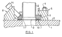
- FIG. 1 shows a partial section of a part of an engine block 1 with an opening 3 opening into a support surface 2
- Contact surface 2 which is also referred to as a sealing surface, is just in the example shown, but not necessarily is required.
- the bearing surface 2 is on one side with a the engine block connected bar 5 limited on their the support surface 2 is undercut.
- a groove 7 in the side facing the support surface 2 Bar 4 formed a groove 7, one side wall of the Support surface 2 of the engine block 1 is formed.
- the floor runs at right angles to the contact surface 2.
- the opposite Side wall of the groove 7 could be designed as an inclined surface be and at an angle of about 30 ° opposite of the contact surface 2 run.
- a projection 8 Through the projection 8 extends a threaded hole into which a clamping screw 14 is screwed in.
- the longitudinal axis of the clamping screw 14 runs at an angle of about 45 ° to the Support surface 2 of the engine block 1. That of the support surface 2 facing underside of the projection 8 could under one Angles of approximately 45 °.
- a flange 10 is located on the contact surface 2 of the engine block 1 placed with the interposition of a sealing plate 9.
- the thin sealing plate 9 has parallel side surfaces.
- the with the interposition of the sealing plate 9 on the support surface 2 of the engine block 1 lying contact surface of the flange 10 is also a flat surface in the example shown, corresponding to the shape of the bearing surface 2 of the engine block 1.
- the flange contains an opening 11, into the tube 12 from the opposite side inserted and attached.
- the tube is 12 welded in the area of its front edge.
- the contact surface of the flange 10 surrounds the opening 11 is provided for the tube 12 on all sides.
- the flange 10 is included provided an inclined surface 13.
- the inclined surface 13 is on the opposite side at an angle of 45 ° to the contact surface trained so that the front end face of the clamping screw 14 rests flat on the inclined surface 13 of the flange 10. Tightening the clamping screw 14 with the help of a Wrench or the like leads to an application of the Flange 10 with a force component in one direction parallel to the contact surface 2. This leads to a slight Displacement of the flange 10 in the direction of the groove 7 and because of the inclined surfaces 13 there, too Pressing the flange onto the sealing surface 2. Simultaneously generates the clamping screw 14 also a contact pressure on the its assigned inclined surface 13.
- the clamping screw 14 is screwed on, until their end face roughly matches the side of the protrusion 8 is aligned. Then the flange 10 can be removed from the groove 7 disengaged and by tilting counterclockwise from the Space between the bar 5 and the projection 8 be taken out.
- This described arrangement can be assembled in such a way that initially with the help of stud bolts, not shown the two strips are screwed onto the engine block 1. Subsequently, the flange 10 in the in FIGS. 6 and 7th shown inserted obliquely on the sealing surface 2 tilted and then using the clamping screws 14 be jammed.
- a stop or an alignment aid may be provided.
- the projection 18 can also be strip-shaped be formed and over the longitudinal direction of the Flange 10 have distributed several clamping screws 14.
- removal can also be done by moving it perpendicular to the cutting plane.
- the Flange three openings for receiving one tube each.
- the flange is elongated and has two end faces and two long sides. In the area of the upper edges of the long sides contains the flange in similar to the flange 11 of FIG. 1 inclined surfaces, which are flatter in the example.
- the two inclined surfaces have the on both long sides same slope on.
- One long side engages in a manner similar to that in FIG. 1 into a groove which is formed on a strip which is integrally formed with the engine block.
- the one Sidewall of this groove forms an associated with the engine block Sloping surface.
- the bearing surface is rectangular limited to her ledge.
- the strips contain several aligned holes, seen in the longitudinal direction of the flange between each two adjacent openings are arranged.
- a clamping strip is placed on the sloping surface of the flange placed on the underside one with the sloping surface cooperating inclined surface associated with the engine block.
- the terminal block contains several transverse ones Threaded holes. Clamping screws are through the holes in the Strip inserted through and are with a front threaded section screwed into the threaded holes of the terminal block. The front free end area of the clamping screws, that has no thread engages with a small radial play into the corresponding holes in the bar. This is the front end area led. Tightening the clamping screw by attacking her screw head leads to a transverse displacement of the terminal block, which is due to the flat contact of the two inclined surfaces for a contact pressure the contact surface of the flange on the contact surface of the engine block.
- the terminal block is provided with incisions that the pipes correspond.
- the clamping screws are loosened and removed the terminal block. Then the flange can again detached from the side groove and up or to the side be removed.
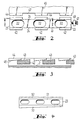
- FIGS. 2 and 3 A further embodiment is shown in FIGS. 2 and 3 a flange 41 proposed by the invention shown.
- the flange 41 has approximately the same arrangement as in the previous embodiment, however 24 individual projections 42 in the area of its long sides arranged, between which space remains.
- the protrusions 42 have inclined surfaces 43 on their upper sides, see also Fig. 3, which are formed increasing in longitudinal section, so that the slope is parallel to the longitudinal direction. All projections 42 have oblique surfaces 43 which are oriented in the same direction on.
- the axial extent of all the projections 42 corresponds to that Distance between two projections 44 of a formation 45 on the engine block. 2, the projections 42 and 44 shown opposite to each other to show that the Projections 42 and 44 are of substantially the same length exhibit.
- the projections 44 point on the engine block side on its underside, see again FIG. 3, inclined surfaces 46 on, the inclination of the inclination of the inclined surfaces 43 is the same is.
- clamping screw 47 serve by an element 48 of the engine block 1 is screwed through and whose axis of rotation extends in the longitudinal direction of the flange 41. In in this case there is an application in one Direction parallel to the sealing surface 2, while the clamping forces are generated exclusively by the inclined surfaces 43, 46.
- FIGS. 2 and 3 enables one Insert without tilting the flange.
- FIG. 4 shows a further embodiment on a smaller scale, in the area of the long sides of the flange 51 Inclined surfaces 52, 53 are present, one of which Inclined surface 52 is formed in the same way as that Inclined surface of the embodiment, not shown, while the inclined surface 53 to both the side edge and Front edge 23 drops off.
- Inclined surface 52 is formed in the same way as that Inclined surface of the embodiment, not shown, while the inclined surface 53 to both the side edge and Front edge 23 drops off.
- the embodiment according to Fig. 4 can also jam by shifting in Longitudinal direction, in this case from left to right.
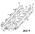
- the terminal block 61 has a plurality of bores 67 for the stud bolts 60 on. The arrangement and spacing of these holes thus corresponds to the stud 60 of the engine block for which the arrangement is determined.
- the terminal block 61 points in the direction of the opposite one Clamping bar 64 directed projections 62 in which the Bores 67 are arranged in pairs. All tabs 62 are on a continuous part 68 of the terminal block 61 trained.
- Recesses 69 are formed between two projections 62, which serve to receive lateral tongues 70 which the longitudinal side of the flange assigned to the terminal strip 61 65 are formed.
- the opposite tension bar 64 has on its Terminal strip 61 facing the inside also a row of projections 71 in which bores 67 for receiving the clamping bolt 60 are included. Between the ledges 71 are the oblique threaded holes for the Clamping screws 14 arranged.
- the flange 65 has on its associated with the clamping bar 64 On the long side also tongues 72 on the same Are arranged longitudinally like the tongues 70 on the opposite long side. On the outside of the tongues 72, the inclined surfaces 66 are formed, on which the Attack the end faces of the clamping screws 14.
- One of the plurality of tongues 70, 72 can be in the longitudinal direction of the flange measured longitudinal dimension that the Distance between the insides of two adjacent protrusions 62 or 71 corresponds. This can help align of the flange 65 can be reached in the longitudinal direction. The remaining Tongues can be used to compensate for length changes in temperature be a little shorter.
- the flange is attached follows. First, the engine block 1 Terminal block 62 and the clamping bar 64 screwed.
- the seal 9 can, for example, if it is made of sheet metal is made with the help of a clip on one or both End faces of the flange 65 are attached.
- the Flange 65 have a recess, a notch or the like.
- the flange to be fastened by clamping action after the Invention has the advantage that it also existing engine blocks can be used. Attaching the two Moldings 61, 64 can be done before mounting the flange, too in a place where there is enough space.
- the strips 64, 64 and the flange 65 are thus one on the other matched that the clamping screws 14 tightened to the stop can be.
- screw lock for the clamping screws 14 can commercially available spring washers or spring washers be used.
Landscapes
- Engineering & Computer Science (AREA)
- General Engineering & Computer Science (AREA)
- Mechanical Engineering (AREA)
- Chemical & Material Sciences (AREA)
- Combustion & Propulsion (AREA)
- Exhaust Silencers (AREA)
- Flanged Joints, Insulating Joints, And Other Joints (AREA)
- Clamps And Clips (AREA)
- Cylinder Crankcases Of Internal Combustion Engines (AREA)
Description
- Fig. 1
- schematisch einen Querschnitt durch eine Flanschverbindung nach der Erfindung;
- Fig. 2
- eine stark vereinfachte Aufsicht auf eine zweite Ausführungsform;
- Fig. 3
- einen Schnitt etwa längs Linie V-V in Fig. 2;
- Fig. 4
- in verkleinertem Maßstab eine Aufsicht auf einen Flansch.
- Fig. 5
- schematisch das Einlegen eines zur Vereinfachung ohne Rohre gezeichneten Flanschs zwischen zwei Leisten;
- Fig. 6
- vereinfacht den Zustand des Flanschs zwischen den beiden Leisten.
Claims (19)
- Verbindung eines Flanschs (10, 41, 65), der1.1 mindestens ein Rohr (12),1.2 eine die Mündung des Rohrs (12) umgebende Anlagefläche sowie1.3 mindestens eine ihm zugeordnete Schrägfläche aufweist, diemit einem Gegenelement (1), das1.3.1 unter einem spitzen Winkel gegenüber der Anlagefläche verläuft,1.4 mindestens eine Öffnung (3),1.5 eine die Öffnung (3) umgebende Auflagefläche (2), die1.5.1 zur gegenseitigen Anlage an der Anlagefläche des Flanschs (10, 41, 65), gegebenenfalls unter Zwischenlage einer Dichtung (9), ausgebildet ist, sowie1.6 mindestens eine ihm zugeordnete Schrägfläche aufweist, die1.6.1 unter einem spitzen Winkel gegenüber der Auflagefläche (2) verläuft und1.6.2 zur Anlage an der Schrägfläche (13, 66) des Flanschs (10, 41, 65) ausgebildet ist, wobei das Gegenelement ein Motorblock (1) ist.
- Verbindung nach Anspruch 1, bei der die dem Gegenelement (1) zugeordnete Schrägfläche an einem mit dem Gegenelement (1) verbindbaren Zusatzelement (8) ausgebildet ist.
- Verbindung nach Anspruch 1 oder 2 mit einer Klemmeinrichtung zur Herstellung einer Verklemmung bzw. Verkeilung zwischen dem Flansch und dem Gegenelement.
- Verbindung nach einem der Ansprüche 1 bis 3, mit mindestens einem Klemmelement, das an dem Flansch (10, 41, 65) und/oder dem Gegenelement (1) mit einer Kraftkomponente mindestens parallel zu der Auflagefläche angreift.
- Verbindung nach Anspruch 3 oder 4, bei der die Klemmeinrichtung eine Klemmschraube (14) aufweist.
- Verbindung nach Anspruch 3 oder 4, bei der die Klemmeinrichtung ein Exzenterelement aufweist.
- Verbindung nach Anspruch 3 oder 4, bei der die Klemmrichtung einen Kniehebel aufweist.
- Verbindung nach einem der vorhergehenden Ansprüche, bei der die dem Flansch (10, 41, 65) zugeordnete Schrägfläche (13, 66) an dem Flansch (10, 41, 65) selbst ausgebildet ist.
- Verbindung nach einem der vorhergehenden Ansprüche, bei der der Flansch (10, 41, 65) an zwei gegenüberliegenden Seiten Schrägflächen (13, 66) aufweist.
- Verbindung nach einem der vorhergehenden Ansprüche, bei der die Schrägflächen (13, 66) des Flanschs (10, 41, 65) nach außen abfallend ausgebildet sind.
- Verbindung nach einem der vorhergehenden Ansprüche, bei der die Schrägflächen (43) des Flanschs (41) in dessen Längsrichtung abfallend ausgebildet sind.
- Verbindung nach einem der vorhergehenden Ansprüche, bei der die Schrägflächen (43, 66) des Flanschs (41, 65) und/oder des Gegenelements (1) an einzelnen Vorsprüngen (42, 44) ausgebildet sind.
- Verbindung nach einem der vorhergehenden Ansprüche, bei der eine dem Gegenelement (1) zugeordnete Schrägfläche von einer Wand einer Nut gebildet wird.
- Verbindung nach einem der Ansprüche 3 bis 14, bei der eine dem Gegenelement (1) zugeordnete Schrägfläche an einem von der Klemmeinrichtung beaufschlagten Teil ausgebildet ist, insbesondere einer Klemmleiste.
- Verbindung nach einem der vorhergehenden Ansprüche, bei dem eine dem Gegenelement (1) zugeordnete Schrägfläche an einer Klemmschraube (14) ausgebildet ist.
- Verbindung nach einem der Ansprüche 2 bis 15, an dem das Zusatzelement vorzugsweise in Form einer für alle Öffnungen (3) durchgehenden Leiste (8) anschraubbar ist, wobei diese insbesondere mit Hilfe der vorhandenen Stehbolzen (4) und/oder den vorhandenen Gewindebohrungen angeschraubt wird.
- Verbindung nach Anspruch 16, bei der der Flansch (10) zwischen zwei Leisten (5, 8) verspannt wird, die beide mit den Stehbolzen (4) befestigt werden.
- Verbindung nach Anspruch 16 oder 17, bei der der Flansch (65) an seiner einen Längsseite Zungen (70, 72) aufweist, die in Ausnehmungen der Leiste einschiebbar sind.
- Verbindung nach einem der vorhergehenden Ansprüche, bei der der Flansch (10, 41, 65) zur Verbindung von Einlaßrohren oder Auslaßrohren ausgebildet ist.
Applications Claiming Priority (4)
| Application Number | Priority Date | Filing Date | Title |
|---|---|---|---|
| DE19934338719 DE4338719A1 (de) | 1993-11-12 | 1993-11-12 | Flanschverbindung |
| DE4338719 | 1993-11-12 | ||
| DE4430339 | 1994-08-26 | ||
| DE4430339A DE4430339A1 (de) | 1993-11-12 | 1994-08-26 | Anordnung zur Flanschverbindung |
Publications (3)
| Publication Number | Publication Date |
|---|---|
| EP0653583A2 EP0653583A2 (de) | 1995-05-17 |
| EP0653583A3 EP0653583A3 (de) | 1996-02-07 |
| EP0653583B1 true EP0653583B1 (de) | 2003-04-02 |
Family
ID=25931182
Family Applications (1)
| Application Number | Title | Priority Date | Filing Date |
|---|---|---|---|
| EP94117702A Expired - Lifetime EP0653583B1 (de) | 1993-11-12 | 1994-11-10 | Flanschverbindung |
Country Status (3)
| Country | Link |
|---|---|
| EP (1) | EP0653583B1 (de) |
| AT (1) | ATE236374T1 (de) |
| DE (2) | DE4430339A1 (de) |
Families Citing this family (16)
| Publication number | Priority date | Publication date | Assignee | Title |
|---|---|---|---|---|
| DE19653908A1 (de) | 1996-12-21 | 1998-06-25 | Daimler Benz Ag | Einrichtung zum Anschluß eines Rohrkrümmers |
| DE102004010815A1 (de) | 2004-03-05 | 2005-09-29 | Benteler Automobiltechnik Gmbh | Anordnung zur Fixierung eines Abgaskrümmers auf dem Zylinderkopf einer Brennkraftmaschine |
| DE102004037865A1 (de) * | 2004-08-04 | 2006-03-16 | Arvin Technologies, Inc., Troy | Abgaskrümmerbefestigungseinrichtung und Verfahren zum Arretieren eines Abgaskrümmers an einem Motorblock |
| FR2897101A1 (fr) * | 2006-02-08 | 2007-08-10 | Renault Sas | Dispositif de fixation d'un collecteur |
| DE102006020608B4 (de) * | 2006-05-02 | 2009-04-23 | Benteler Automobiltechnik Gmbh | Anordnung und Verfahren zur Fixierung eines Abgasrohrs an einem Zylinderkopf |
| DE102007002825B4 (de) * | 2007-01-19 | 2008-12-11 | Audi Ag | Klemmflanschanordnung zum Anschluss einer Auspuffanlage an eine Brennkraftmaschine |
| WO2009003668A1 (de) * | 2007-06-29 | 2009-01-08 | Borgwarner Inc. | Verbindungseinrichtung zur befestigung eines auslasskrümers am zylinderkopf eines verbrennungsmotors |
| DE102008060028A1 (de) * | 2008-12-02 | 2010-06-10 | Audi Ag | Brennkraftmaschine und Verfahren zur Montage eines Heißgas führenden Anbauteils an einem Zylinderkopf |
| AT509691B1 (de) | 2010-03-18 | 2013-09-15 | Avl List Gmbh | Brennkraftmaschine mit einer verbindungsanordnung für einen zylinderkopf |
| AT509689B1 (de) | 2010-03-18 | 2015-02-15 | Avl List Gmbh | Zylinderkopf-abgassammleranordnung |
| AT509690B1 (de) | 2010-03-18 | 2013-10-15 | Avl List Gmbh | Brennkraftmaschine mit einer verbindungsanordnung für einen zylinderkopf |
| AT508409B1 (de) | 2010-06-24 | 2013-09-15 | Avl List Gmbh | Brennkraftmaschine mit einer verbindungsanordnung für einen zylinderkopf |
| FR2965307B1 (fr) * | 2010-09-28 | 2012-09-14 | Valeo Systemes Thermiques | Dispositif d'admission de fluide pour moteur, en particulier d'un vehicule automobile, et echangeur de chaleur correspondant |
| DE102011009340A1 (de) * | 2011-01-25 | 2012-07-26 | GM Global Technology Operations LLC (n. d. Ges. d. Staates Delaware) | Befestigungseinrichtung zur Befestigung eines Abgaskrümmers mit einem Zylinderkopf |
| CN102230415A (zh) * | 2011-06-13 | 2011-11-02 | 奇瑞汽车股份有限公司 | 一种排气歧管安装结构及其安装、拆卸方法 |
| DE102013016568B4 (de) * | 2013-10-04 | 2016-03-24 | Audi Ag | Brennkraftmaschine sowie Verfahren zum Montieren einer Brennkraftmaschine |
Family Cites Families (5)
| Publication number | Priority date | Publication date | Assignee | Title |
|---|---|---|---|---|
| US2831708A (en) * | 1954-07-21 | 1958-04-22 | Standard Oil Co | Flange unit for laterally insertable pipe section |
| US3439940A (en) * | 1965-06-21 | 1969-04-22 | Ritter Pfaudler Corp | Connection with a glass coated sealing surface |
| GB1133351A (en) * | 1965-09-08 | 1968-11-13 | William Ernest Stevens | Improvements in or relating to pipe joints |
| CA2075085A1 (en) * | 1992-07-31 | 1994-02-01 | Sylvain Boivin | Conduit system |
| DE4313091A1 (de) * | 1993-04-22 | 1994-10-27 | Bischoff Erhardt Gmbh Co Kg | Flansch zur Befestigung von Rohren |
-
1994
- 1994-08-26 DE DE4430339A patent/DE4430339A1/de not_active Withdrawn
- 1994-11-10 DE DE59410264T patent/DE59410264D1/de not_active Expired - Fee Related
- 1994-11-10 EP EP94117702A patent/EP0653583B1/de not_active Expired - Lifetime
- 1994-11-10 AT AT94117702T patent/ATE236374T1/de not_active IP Right Cessation
Also Published As
| Publication number | Publication date |
|---|---|
| DE4430339A1 (de) | 1996-02-29 |
| ATE236374T1 (de) | 2003-04-15 |
| EP0653583A3 (de) | 1996-02-07 |
| DE59410264D1 (de) | 2003-05-08 |
| EP0653583A2 (de) | 1995-05-17 |
Similar Documents
| Publication | Publication Date | Title |
|---|---|---|
| EP1956250B1 (de) | Schienenartiges Profil | |
| EP0653583A2 (de) | Flanschverbindung | |
| DE10357844B4 (de) | Befestigungssystem | |
| EP2663815A1 (de) | Befestigungssystem zur montage von solarmodulen auf einem trapezblech | |
| EP2612041A1 (de) | Käfigmutter | |
| DE3920678C2 (de) | Filterdüse | |
| DE2737537A1 (de) | Element zum bilden einer mutter | |
| WO2012167895A1 (de) | System zum befestigen von solarmodulen | |
| DE102019202156A1 (de) | Befestigungsanordnung, Toleranzausgleichsanordnung für eine Befestigungseinrichtung und Montageverfahren zum Befestigen eines Batteriemoduls an einer Kühlvorrichtung | |
| EP0904463B1 (de) | Vorrichtung zur lagefixierung von formkörpern einer gleisübergangseinrichtung an einer gleisanlage | |
| EP2372269A2 (de) | Verbindungsvorrichtung und Profilanordnung | |
| DE4338719A1 (de) | Flanschverbindung | |
| DE102022200720A1 (de) | Batteriesystem mit Druckvorrichtung und Kraftfahrzeug | |
| DE102004017449B4 (de) | Befestigungsclip zur Anordnung eines Bauteils an einem Stehbolzen o. dgl. | |
| EP0551836A1 (de) | Schraubverbindung zwischen einer Profilschiene und einem Beschlag oder einem sonstigen Bauteil | |
| EP1388308A1 (de) | Montageteil zum temporären Halten und Fixieren | |
| DE202011003315U1 (de) | Verbindungsvorrichtung | |
| DE3231114A1 (de) | Verbindungssystem | |
| DE3420261A1 (de) | Befestigungsschelle fuer kabel und rohre mit grossem durchmesserbereich | |
| DE19714193C2 (de) | Vorrichtung zum Befestigen von Bauelementen | |
| BE1031648B1 (de) | Befestigungselement für eine Fassadenplatte und Anordnung mit einer Fassadenplatte und dem Befestigungselement | |
| AT525700B1 (de) | Verbindungsanordnung und Profilverbindungsanordnung | |
| EP0866231B1 (de) | Vorgefertigte Befestigungsvorrichtung | |
| DE202013100120U1 (de) | T-Verbindung für eine Pfosten-Riegel-Konstruktion | |
| EP2221490B1 (de) | Einteiliges Befestigungselement zur Anordnung eines Stangenelementes an einer Montageschiene |
Legal Events
| Date | Code | Title | Description |
|---|---|---|---|
| PUAI | Public reference made under article 153(3) epc to a published international application that has entered the european phase |
Free format text: ORIGINAL CODE: 0009012 |
|
| AK | Designated contracting states |
Kind code of ref document: A2 Designated state(s): AT BE DE ES FR GB IT SE |
|
| PUAL | Search report despatched |
Free format text: ORIGINAL CODE: 0009013 |
|
| RHK1 | Main classification (correction) |
Ipc: F16L 41/08 |
|
| AK | Designated contracting states |
Kind code of ref document: A3 Designated state(s): AT BE DE ES FR GB IT SE |
|
| RAP1 | Party data changed (applicant data changed or rights of an application transferred) |
Owner name: ERHARDT BISCHOFF GMBH & CO KG |
|
| 17P | Request for examination filed |
Effective date: 19960806 |
|
| 17Q | First examination report despatched |
Effective date: 19980515 |
|
| GRAG | Despatch of communication of intention to grant |
Free format text: ORIGINAL CODE: EPIDOS AGRA |
|
| GRAG | Despatch of communication of intention to grant |
Free format text: ORIGINAL CODE: EPIDOS AGRA |
|
| GRAH | Despatch of communication of intention to grant a patent |
Free format text: ORIGINAL CODE: EPIDOS IGRA |
|
| GRAH | Despatch of communication of intention to grant a patent |
Free format text: ORIGINAL CODE: EPIDOS IGRA |
|
| RAP1 | Party data changed (applicant data changed or rights of an application transferred) |
Owner name: HEINRICH GILLET GMBH & CO. KG |
|
| GRAA | (expected) grant |
Free format text: ORIGINAL CODE: 0009210 |
|
| AK | Designated contracting states |
Designated state(s): AT BE DE ES FR GB IT SE |
|
| PG25 | Lapsed in a contracting state [announced via postgrant information from national office to epo] |
Ref country code: IT Free format text: LAPSE BECAUSE OF FAILURE TO SUBMIT A TRANSLATION OF THE DESCRIPTION OR TO PAY THE FEE WITHIN THE PRE;WARNING: LAPSES OF ITALIAN PATENTS WITH EFFECTIVE DATE BEFORE 2007 MAY HAVE OCCURRED AT ANY TIME BEFORE 2007. THE CORRECT EFFECTIVE DATE MAY BE DIFFERENT FROM THE ONE RECORDED.SCRIBED TIME-LIMIT Effective date: 20030402 Ref country code: GB Free format text: LAPSE BECAUSE OF FAILURE TO SUBMIT A TRANSLATION OF THE DESCRIPTION OR TO PAY THE FEE WITHIN THE PRESCRIBED TIME-LIMIT Effective date: 20030402 Ref country code: FR Free format text: LAPSE BECAUSE OF FAILURE TO SUBMIT A TRANSLATION OF THE DESCRIPTION OR TO PAY THE FEE WITHIN THE PRESCRIBED TIME-LIMIT Effective date: 20030402 |
|
| REG | Reference to a national code |
Ref country code: GB Ref legal event code: FG4D Free format text: NOT ENGLISH |
|
| REF | Corresponds to: |
Ref document number: 59410264 Country of ref document: DE Date of ref document: 20030508 Kind code of ref document: P |
|
| PG25 | Lapsed in a contracting state [announced via postgrant information from national office to epo] |
Ref country code: SE Free format text: LAPSE BECAUSE OF FAILURE TO SUBMIT A TRANSLATION OF THE DESCRIPTION OR TO PAY THE FEE WITHIN THE PRESCRIBED TIME-LIMIT Effective date: 20030702 |
|
| GBV | Gb: ep patent (uk) treated as always having been void in accordance with gb section 77(7)/1977 [no translation filed] |
Effective date: 20030402 |
|
| PG25 | Lapsed in a contracting state [announced via postgrant information from national office to epo] |
Ref country code: ES Free format text: LAPSE BECAUSE OF FAILURE TO SUBMIT A TRANSLATION OF THE DESCRIPTION OR TO PAY THE FEE WITHIN THE PRESCRIBED TIME-LIMIT Effective date: 20031030 |
|
| PG25 | Lapsed in a contracting state [announced via postgrant information from national office to epo] |
Ref country code: AT Free format text: LAPSE BECAUSE OF NON-PAYMENT OF DUE FEES Effective date: 20031110 |
|
| PGFP | Annual fee paid to national office [announced via postgrant information from national office to epo] |
Ref country code: DE Payment date: 20031119 Year of fee payment: 10 |
|
| PG25 | Lapsed in a contracting state [announced via postgrant information from national office to epo] |
Ref country code: BE Free format text: LAPSE BECAUSE OF NON-PAYMENT OF DUE FEES Effective date: 20031130 |
|
| PLBE | No opposition filed within time limit |
Free format text: ORIGINAL CODE: 0009261 |
|
| STAA | Information on the status of an ep patent application or granted ep patent |
Free format text: STATUS: NO OPPOSITION FILED WITHIN TIME LIMIT |
|
| EN | Fr: translation not filed | ||
| 26N | No opposition filed |
Effective date: 20040105 |
|
| BERE | Be: lapsed |
Owner name: HEINRICH *ILLET G.M.B.H. & CO. K.G. Effective date: 20031130 |
|
| PG25 | Lapsed in a contracting state [announced via postgrant information from national office to epo] |
Ref country code: DE Free format text: LAPSE BECAUSE OF NON-PAYMENT OF DUE FEES Effective date: 20050601 |