EP0653372A2 - Seilkompensation pour Aufzug - Google Patents
Seilkompensation pour Aufzug Download PDFInfo
- Publication number
- EP0653372A2 EP0653372A2 EP94118029A EP94118029A EP0653372A2 EP 0653372 A2 EP0653372 A2 EP 0653372A2 EP 94118029 A EP94118029 A EP 94118029A EP 94118029 A EP94118029 A EP 94118029A EP 0653372 A2 EP0653372 A2 EP 0653372A2
- Authority
- EP
- European Patent Office
- Prior art keywords
- counterweight
- compensation
- elevator car
- car
- elevator
- Prior art date
- Legal status (The legal status is an assumption and is not a legal conclusion. Google has not performed a legal analysis and makes no representation as to the accuracy of the status listed.)
- Withdrawn
Links
Images


Classifications
-
- B—PERFORMING OPERATIONS; TRANSPORTING
- B66—HOISTING; LIFTING; HAULING
- B66B—ELEVATORS; ESCALATORS OR MOVING WALKWAYS
- B66B7/00—Other common features of elevators
- B66B7/06—Arrangements of ropes or cables
- B66B7/068—Cable weight compensating devices
Definitions
- the present invention relates to a compensation arrangement in an elevator as defined in the preamble of claim 1.
- rope compensation There are two different types of rope compensation.
- a rope, belt or chain can be used, and these can be lined with rubber or plastic and they often contain additional masses attached to them.
- These ropes, belts or chains are mounted as loops below and between the car and counterweight and they are preferably attached to the lower parts of the car and counterweight.
- the range of application of this rope compensation is limited to relatively low speeds because of the danger of swinging.
- the speed of the rope, belt or chain is the same as that of the elevator. This speed occurring at the culmination point of the loop is called the loop circulation speed.
- the speed of the elevator is changed during acceleration or deceleration, then the speed of the loop will be changed as well and the cable starts to swing. The larger the speed range, the greater is the danger that the swinging will result in the rope, belt or chain being caught on a piece of shaft equipment.
- the additional masses used are generally a rope or ropes hanging in the form of loops below and between the car and counterweight.
- these loops are tightened by means of a tensioning device.
- the solution of the invention eliminates these drawbacks by rendering the expensive tension weight unnecessary and halving the loop speed as compared to the old loop.
- This is achieved by suspending the compensating ropes so that they run from the underside of the elevator car to fixing points in the wall and, similarly, from the underside of the counterweight to fixing points in the shaft wall.
- Both compensation loops are attached to the shaft wall at a point at or above the midpoint of the path of the elevator car or counterweight. When the car moves in the down direction, both the car cable loop and the compensation loop move downwards and the loop circulation speed is only half the travelling speed of the car.
- the counterweight moves in the up direction and its compensation loop move upwards.
- the circulation speed of the counterweight compensation loop is half the travelling speed of the counterweight.
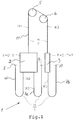
- Fig. 1 illustrates the structure of the solution of the invention. It shows an elevator 1 with an elevator car 2 suspended to a ratio of 1:1 and a counterweight 3 suspended by means of a diverting pulley 6 to a ratio of 1:1 , elevator ropes 11 supporting the elevator car 2 and counterweight 3, and a traction sheave 5 whose motion is transmitted via the ropes to the elevator car 2 and counterweight 3.
- the car cable 4 is preferably passed from the car 2 to a fixing point 8 in a wall of the elevator shaft, and the compensation loop 7a is also passed from the car 2 to a fixing point 9 in a shaft wall.
- the compensation loop 7b below the counterweight 3 is attached to a fixing point 10 in a shaft wall.
- the compensation loops 7a and 7b are attached to the shaft wall at a point located at or above the midpoint of the path of the elevator car 2 or counterweight 3.
- the point of attachment of the car cable 4 is at the same height as that of the compensation ropes.
- the circulation speed of the compensation loop 7b for the counterweight 3 is half the travelling speed of the counterweight, and the circulation speed of the compensation loop 7a for the elevator car 2 is half the travelling speed of the car 2.
- the loop length hanging from the elevator car 2 is at this point half the total loop length, i.e. about 1 ⁇ 4 of the travel height H.
- the mass/measure of the car cable 4 is M2 and the mass/measure of compensation loop 7a is M3.
- the coun terweight 3 contains the mass of the elevator car 2 + balanc ing percentage * nominal load + a so-called cable setoff .
- Below the counterweight 3 hings the counterweight compensation loop 7b, in which the portion hanging from the counterweight 3 equals 1 ⁇ 4 of the travel height H.
- the mass of this compensation loop, too, is M3/measure.
- the bare weight of the elevator car 2 is P
- the nominal load is Q
- the counterweight balancing degree is T
- X is an extra mass which is added to the counterweight 3 to achieve balance midway in the shaft.
- Fig. 2 presents a situation where the car is near the top of the shaft and the counterweight is near the bottom.
- Fig. 3 presents a situation where the car is near the bottom of the shaft and the counterweight is near the top.
- Fig. 5 presents a solution which can be used in patents FI 82823.
- the counterweight 3 is twice as heavy as in the above-mentioned figures 1-4 and the path and speed of the counterweight 3 are half those of the elevator car 2.
- Fig. 5 shows the elevator car 2 in its extreme positions. The result in this case, too, is a fully compensated solution.
- the mass/measure of the compensation loop 7b for the counterweight 3 is larger than the mass/measure of the compensation loop 7a for the elevator car 2.
- the necessary equations can be solved by determining appropriate balancing equations for different solutions regarding the elevator car 2 and the counterweight 3. The equations depend on the location of the path of the counterweight 3, which may vary from case to case.
Applications Claiming Priority (2)
| Application Number | Priority Date | Filing Date | Title |
|---|---|---|---|
| FI935060A FI91850C (fi) | 1993-11-16 | 1993-11-16 | Kompensaatiojärjestely |
| FI935060 | 1993-11-16 |
Publications (2)
| Publication Number | Publication Date |
|---|---|
| EP0653372A2 true EP0653372A2 (de) | 1995-05-17 |
| EP0653372A3 EP0653372A3 (de) | 1995-09-13 |
Family
ID=8538959
Family Applications (1)
| Application Number | Title | Priority Date | Filing Date |
|---|---|---|---|
| EP94118029A Withdrawn EP0653372A3 (de) | 1993-11-16 | 1994-11-15 | Seilkompensation pour Aufzug. |
Country Status (5)
| Country | Link |
|---|---|
| EP (1) | EP0653372A3 (de) |
| JP (1) | JPH07187543A (de) |
| AU (1) | AU7883494A (de) |
| CA (1) | CA2135818A1 (de) |
| FI (1) | FI91850C (de) |
Cited By (6)
| Publication number | Priority date | Publication date | Assignee | Title |
|---|---|---|---|---|
| EP1234796A1 (de) * | 2001-02-27 | 2002-08-28 | Brugg Drahtseil AG | Anordnung für Gewichtsausgleichselemente |
| DE10305275A1 (de) * | 2003-02-07 | 2004-08-26 | Wittur Ag | Aufzuganlage mit Ausgleich der Tragseilmassen |
| EP1790608A1 (de) * | 2005-11-28 | 2007-05-30 | Inventio Ag | Aufzugsanlage mit Einrichtung zur Kompensation des Gewichtsunterschieds zwischen den Kabinentrumen und den Gegengewichtstrumen der Tragmittel und Verfahren zur Realisierung einer solchen Kompensation |
| US8087497B2 (en) * | 2004-12-29 | 2012-01-03 | Otis Elevator Company | Compensation in an elevator system having multiple cars within a single hoistway |
| WO2012034899A1 (de) | 2010-09-17 | 2012-03-22 | Inventio Ag | Aufzug mit einer aufzugskabine und einem gegengewicht |
| CN101219746B (zh) * | 2007-01-10 | 2012-05-23 | 株式会社日立制作所 | 电梯设备 |
Citations (1)
| Publication number | Priority date | Publication date | Assignee | Title |
|---|---|---|---|---|
| EP0385255A1 (de) * | 1989-02-28 | 1990-09-05 | Otis Elevator Company | Seilgewichtkompensationsgerät für einen linearmotorangetriebenen Aufzug |
Family Cites Families (1)
| Publication number | Priority date | Publication date | Assignee | Title |
|---|---|---|---|---|
| JPS5925347B2 (ja) * | 1980-05-21 | 1984-06-16 | 富士通株式会社 | 試験時におけるディアルインラインパッケ−ジ形半導体集積回路の搭載方法 |
-
1993
- 1993-11-16 FI FI935060A patent/FI91850C/fi active IP Right Grant
-
1994
- 1994-11-15 EP EP94118029A patent/EP0653372A3/de not_active Withdrawn
- 1994-11-15 CA CA 2135818 patent/CA2135818A1/en not_active Abandoned
- 1994-11-16 AU AU78834/94A patent/AU7883494A/en not_active Abandoned
- 1994-11-16 JP JP30569394A patent/JPH07187543A/ja active Pending
Patent Citations (1)
| Publication number | Priority date | Publication date | Assignee | Title |
|---|---|---|---|---|
| EP0385255A1 (de) * | 1989-02-28 | 1990-09-05 | Otis Elevator Company | Seilgewichtkompensationsgerät für einen linearmotorangetriebenen Aufzug |
Non-Patent Citations (1)
| Title |
|---|
| F.A. ANNETT 'Elevators' 1960 , MCGRAW-HILL BOOK COMPANY, INC. , NEW YORK * page 76 - page 77, line 1 * * page 78, last line - page 79, line 16 * * figures 2-23 2-24 * * |
Cited By (8)
| Publication number | Priority date | Publication date | Assignee | Title |
|---|---|---|---|---|
| EP1234796A1 (de) * | 2001-02-27 | 2002-08-28 | Brugg Drahtseil AG | Anordnung für Gewichtsausgleichselemente |
| WO2002068307A1 (de) * | 2001-02-27 | 2002-09-06 | Brugg Drahtseil Ag | Anordnung für gewichtsausgleichelemente |
| DE10305275A1 (de) * | 2003-02-07 | 2004-08-26 | Wittur Ag | Aufzuganlage mit Ausgleich der Tragseilmassen |
| DE10305275B4 (de) * | 2003-02-07 | 2005-05-25 | Wittur Ag | Aufzuganlage mit Ausgleich der Tragseilmassen |
| US8087497B2 (en) * | 2004-12-29 | 2012-01-03 | Otis Elevator Company | Compensation in an elevator system having multiple cars within a single hoistway |
| EP1790608A1 (de) * | 2005-11-28 | 2007-05-30 | Inventio Ag | Aufzugsanlage mit Einrichtung zur Kompensation des Gewichtsunterschieds zwischen den Kabinentrumen und den Gegengewichtstrumen der Tragmittel und Verfahren zur Realisierung einer solchen Kompensation |
| CN101219746B (zh) * | 2007-01-10 | 2012-05-23 | 株式会社日立制作所 | 电梯设备 |
| WO2012034899A1 (de) | 2010-09-17 | 2012-03-22 | Inventio Ag | Aufzug mit einer aufzugskabine und einem gegengewicht |
Also Published As
| Publication number | Publication date |
|---|---|
| FI935060A0 (fi) | 1993-11-16 |
| AU7883494A (en) | 1995-05-25 |
| FI91850B (fi) | 1994-05-13 |
| CA2135818A1 (en) | 1995-05-17 |
| FI91850C (fi) | 1994-08-25 |
| EP0653372A3 (de) | 1995-09-13 |
| JPH07187543A (ja) | 1995-07-25 |
Similar Documents
| Publication | Publication Date | Title |
|---|---|---|
| US5513724A (en) | Compensation and rope elongation arrangement | |
| US8235179B2 (en) | Elevator without a counterweight | |
| AU760720B2 (en) | Traction sheave elevator | |
| US7207421B2 (en) | Elevator | |
| JP5524448B2 (ja) | エレベータ | |
| US8127893B2 (en) | Elevator and arrangement | |
| FI953153A (fi) | Vetopy¦rähissi | |
| US6966408B2 (en) | Autobalance roping and drive arrangement | |
| US5351788A (en) | Rope arrangement for an elevator car | |
| US10059565B2 (en) | Reducing elongation of roping or belting of an elevator by pretensioning the roping or belting of the elevator | |
| FI118079B (fi) | Hissi, menetelmä hissin liikkeen estämiseksi ja/tai pysäyttämiseksi ja hissikorin liikkeen estävän ja/tai pysäyttävän laitteen käyttö hississä | |
| EP0653372A2 (de) | Seilkompensation pour Aufzug | |
| KR20080055706A (ko) | 승강기 설비 | |
| JPH0351285A (ja) | エレベータかごのバランス調整装置 | |
| KR940005486A (ko) | 엘리베이터 장치 | |
| KR20190003378A (ko) | 로드 베어링 부재의 요동을 감소시키기 위한 다수의 리더 | |
| KR102507242B1 (ko) | 엘리베이터의 서스펜션 설비의 장력을 최적화하는 방법 및 장치 | |
| FI94854B (fi) | Kompensaatioköysijärjestely | |
| JPS6233193B2 (de) | ||
| JPS591670B2 (ja) | エレベ−タ−制御装置用駆動装置 | |
| JPH06115852A (ja) | エレベータのロープアンバランス補償装置 |
Legal Events
| Date | Code | Title | Description |
|---|---|---|---|
| PUAI | Public reference made under article 153(3) epc to a published international application that has entered the european phase |
Free format text: ORIGINAL CODE: 0009012 |
|
| AK | Designated contracting states |
Kind code of ref document: A2 Designated state(s): AT BE CH DE DK ES FR GB GR IE IT LI LU MC NL PT SE |
|
| RAX | Requested extension states of the european patent have changed |
Free format text: LT PAYMENT 941214;SI PAYMENT 941214 |
|
| PUAL | Search report despatched |
Free format text: ORIGINAL CODE: 0009013 |
|
| AK | Designated contracting states |
Kind code of ref document: A3 Designated state(s): AT BE CH DE DK ES FR GB GR IE IT LI LU MC NL PT SE |
|
| STAA | Information on the status of an ep patent application or granted ep patent |
Free format text: STATUS: THE APPLICATION IS DEEMED TO BE WITHDRAWN |
|
| 18D | Application deemed to be withdrawn |
Effective date: 19960314 |