EP0652625B1 - Elektrischer Antrieb mit Bremse, insbesondere für Hebezeuge, Hubeinrichtungen oder positionierende Förderanlagen - Google Patents
Elektrischer Antrieb mit Bremse, insbesondere für Hebezeuge, Hubeinrichtungen oder positionierende Förderanlagen Download PDFInfo
- Publication number
- EP0652625B1 EP0652625B1 EP94250254A EP94250254A EP0652625B1 EP 0652625 B1 EP0652625 B1 EP 0652625B1 EP 94250254 A EP94250254 A EP 94250254A EP 94250254 A EP94250254 A EP 94250254A EP 0652625 B1 EP0652625 B1 EP 0652625B1
- Authority
- EP
- European Patent Office
- Prior art keywords
- yokes
- brake
- electric drive
- drive according
- magnet
- Prior art date
- Legal status (The legal status is an assumption and is not a legal conclusion. Google has not performed a legal analysis and makes no representation as to the accuracy of the status listed.)
- Expired - Lifetime
Links
- 239000004033 plastic Substances 0.000 claims description 14
- 229920003023 plastic Polymers 0.000 claims description 14
- 238000006073 displacement reaction Methods 0.000 claims description 4
- 238000004804 winding Methods 0.000 claims description 4
- 238000004873 anchoring Methods 0.000 claims 4
- 230000002146 bilateral effect Effects 0.000 claims 2
- 230000000694 effects Effects 0.000 claims 1
- 230000006835 compression Effects 0.000 description 4
- 238000007906 compression Methods 0.000 description 4
- 229910000831 Steel Inorganic materials 0.000 description 3
- 239000010959 steel Substances 0.000 description 3
- 238000005299 abrasion Methods 0.000 description 2
- 230000035939 shock Effects 0.000 description 2
- 230000002123 temporal effect Effects 0.000 description 2
- 239000002131 composite material Substances 0.000 description 1
- 230000007797 corrosion Effects 0.000 description 1
- 238000005260 corrosion Methods 0.000 description 1
- 230000006378 damage Effects 0.000 description 1
- 230000005611 electricity Effects 0.000 description 1
- 230000002349 favourable effect Effects 0.000 description 1
- 239000002991 molded plastic Substances 0.000 description 1
- 230000000149 penetrating effect Effects 0.000 description 1
- 230000000737 periodic effect Effects 0.000 description 1
- 230000000284 resting effect Effects 0.000 description 1
- 238000009423 ventilation Methods 0.000 description 1
Images



Classifications
-
- B—PERFORMING OPERATIONS; TRANSPORTING
- B66—HOISTING; LIFTING; HAULING
- B66D—CAPSTANS; WINCHES; TACKLES, e.g. PULLEY BLOCKS; HOISTS
- B66D5/00—Braking or detent devices characterised by application to lifting or hoisting gear, e.g. for controlling the lowering of loads
- B66D5/02—Crane, lift hoist, or winch brakes operating on drums, barrels, or ropes
- B66D5/12—Crane, lift hoist, or winch brakes operating on drums, barrels, or ropes with axial effect
- B66D5/14—Crane, lift hoist, or winch brakes operating on drums, barrels, or ropes with axial effect embodying discs
-
- B—PERFORMING OPERATIONS; TRANSPORTING
- B66—HOISTING; LIFTING; HAULING
- B66D—CAPSTANS; WINCHES; TACKLES, e.g. PULLEY BLOCKS; HOISTS
- B66D5/00—Braking or detent devices characterised by application to lifting or hoisting gear, e.g. for controlling the lowering of loads
- B66D5/02—Crane, lift hoist, or winch brakes operating on drums, barrels, or ropes
- B66D5/24—Operating devices
- B66D5/30—Operating devices electrical
-
- F—MECHANICAL ENGINEERING; LIGHTING; HEATING; WEAPONS; BLASTING
- F16—ENGINEERING ELEMENTS AND UNITS; GENERAL MEASURES FOR PRODUCING AND MAINTAINING EFFECTIVE FUNCTIONING OF MACHINES OR INSTALLATIONS; THERMAL INSULATION IN GENERAL
- F16D—COUPLINGS FOR TRANSMITTING ROTATION; CLUTCHES; BRAKES
- F16D55/00—Brakes with substantially-radial braking surfaces pressed together in axial direction, e.g. disc brakes
- F16D55/24—Brakes with substantially-radial braking surfaces pressed together in axial direction, e.g. disc brakes with a plurality of axially-movable discs, lamellae, or pads, pressed from one side towards an axially-located member
- F16D55/26—Brakes with substantially-radial braking surfaces pressed together in axial direction, e.g. disc brakes with a plurality of axially-movable discs, lamellae, or pads, pressed from one side towards an axially-located member without self-tightening action
- F16D55/28—Brakes with only one rotating disc
-
- F—MECHANICAL ENGINEERING; LIGHTING; HEATING; WEAPONS; BLASTING
- F16—ENGINEERING ELEMENTS AND UNITS; GENERAL MEASURES FOR PRODUCING AND MAINTAINING EFFECTIVE FUNCTIONING OF MACHINES OR INSTALLATIONS; THERMAL INSULATION IN GENERAL
- F16D—COUPLINGS FOR TRANSMITTING ROTATION; CLUTCHES; BRAKES
- F16D59/00—Self-acting brakes, e.g. coming into operation at a predetermined speed
- F16D59/02—Self-acting brakes, e.g. coming into operation at a predetermined speed spring-loaded and adapted to be released by mechanical, fluid, or electromagnetic means
-
- F—MECHANICAL ENGINEERING; LIGHTING; HEATING; WEAPONS; BLASTING
- F16—ENGINEERING ELEMENTS AND UNITS; GENERAL MEASURES FOR PRODUCING AND MAINTAINING EFFECTIVE FUNCTIONING OF MACHINES OR INSTALLATIONS; THERMAL INSULATION IN GENERAL
- F16D—COUPLINGS FOR TRANSMITTING ROTATION; CLUTCHES; BRAKES
- F16D65/00—Parts or details
- F16D65/02—Braking members; Mounting thereof
- F16D65/12—Discs; Drums for disc brakes
-
- H—ELECTRICITY
- H02—GENERATION; CONVERSION OR DISTRIBUTION OF ELECTRIC POWER
- H02K—DYNAMO-ELECTRIC MACHINES
- H02K7/00—Arrangements for handling mechanical energy structurally associated with dynamo-electric machines, e.g. structural association with mechanical driving motors or auxiliary dynamo-electric machines
- H02K7/10—Structural association with clutches, brakes, gears, pulleys or mechanical starters
- H02K7/102—Structural association with clutches, brakes, gears, pulleys or mechanical starters with friction brakes
- H02K7/1021—Magnetically influenced friction brakes
- H02K7/1023—Magnetically influenced friction brakes using electromagnets
- H02K7/1025—Magnetically influenced friction brakes using electromagnets using axial electromagnets with generally annular air gap
-
- F—MECHANICAL ENGINEERING; LIGHTING; HEATING; WEAPONS; BLASTING
- F16—ENGINEERING ELEMENTS AND UNITS; GENERAL MEASURES FOR PRODUCING AND MAINTAINING EFFECTIVE FUNCTIONING OF MACHINES OR INSTALLATIONS; THERMAL INSULATION IN GENERAL
- F16D—COUPLINGS FOR TRANSMITTING ROTATION; CLUTCHES; BRAKES
- F16D55/00—Brakes with substantially-radial braking surfaces pressed together in axial direction, e.g. disc brakes
- F16D2055/0004—Parts or details of disc brakes
- F16D2055/0058—Fully lined, i.e. braking surface extending over the entire disc circumference
-
- F—MECHANICAL ENGINEERING; LIGHTING; HEATING; WEAPONS; BLASTING
- F16—ENGINEERING ELEMENTS AND UNITS; GENERAL MEASURES FOR PRODUCING AND MAINTAINING EFFECTIVE FUNCTIONING OF MACHINES OR INSTALLATIONS; THERMAL INSULATION IN GENERAL
- F16D—COUPLINGS FOR TRANSMITTING ROTATION; CLUTCHES; BRAKES
- F16D65/00—Parts or details
- F16D65/02—Braking members; Mounting thereof
- F16D2065/13—Parts or details of discs or drums
- F16D2065/1304—Structure
- F16D2065/1316—Structure radially segmented
-
- F—MECHANICAL ENGINEERING; LIGHTING; HEATING; WEAPONS; BLASTING
- F16—ENGINEERING ELEMENTS AND UNITS; GENERAL MEASURES FOR PRODUCING AND MAINTAINING EFFECTIVE FUNCTIONING OF MACHINES OR INSTALLATIONS; THERMAL INSULATION IN GENERAL
- F16D—COUPLINGS FOR TRANSMITTING ROTATION; CLUTCHES; BRAKES
- F16D65/00—Parts or details
- F16D65/02—Braking members; Mounting thereof
- F16D2065/13—Parts or details of discs or drums
- F16D2065/1304—Structure
- F16D2065/132—Structure layered
-
- F—MECHANICAL ENGINEERING; LIGHTING; HEATING; WEAPONS; BLASTING
- F16—ENGINEERING ELEMENTS AND UNITS; GENERAL MEASURES FOR PRODUCING AND MAINTAINING EFFECTIVE FUNCTIONING OF MACHINES OR INSTALLATIONS; THERMAL INSULATION IN GENERAL
- F16D—COUPLINGS FOR TRANSMITTING ROTATION; CLUTCHES; BRAKES
- F16D65/00—Parts or details
- F16D65/02—Braking members; Mounting thereof
- F16D2065/13—Parts or details of discs or drums
- F16D2065/1304—Structure
- F16D2065/1324—Structure carrying friction elements
-
- F—MECHANICAL ENGINEERING; LIGHTING; HEATING; WEAPONS; BLASTING
- F16—ENGINEERING ELEMENTS AND UNITS; GENERAL MEASURES FOR PRODUCING AND MAINTAINING EFFECTIVE FUNCTIONING OF MACHINES OR INSTALLATIONS; THERMAL INSULATION IN GENERAL
- F16D—COUPLINGS FOR TRANSMITTING ROTATION; CLUTCHES; BRAKES
- F16D65/00—Parts or details
- F16D65/02—Braking members; Mounting thereof
- F16D2065/13—Parts or details of discs or drums
- F16D2065/134—Connection
- F16D2065/1356—Connection interlocking
- F16D2065/1368—Connection interlocking with relative movement both radially and axially
-
- F—MECHANICAL ENGINEERING; LIGHTING; HEATING; WEAPONS; BLASTING
- F16—ENGINEERING ELEMENTS AND UNITS; GENERAL MEASURES FOR PRODUCING AND MAINTAINING EFFECTIVE FUNCTIONING OF MACHINES OR INSTALLATIONS; THERMAL INSULATION IN GENERAL
- F16D—COUPLINGS FOR TRANSMITTING ROTATION; CLUTCHES; BRAKES
- F16D65/00—Parts or details
- F16D65/02—Braking members; Mounting thereof
- F16D2065/13—Parts or details of discs or drums
- F16D2065/134—Connection
- F16D2065/1388—Connection to shaft or axle
-
- F—MECHANICAL ENGINEERING; LIGHTING; HEATING; WEAPONS; BLASTING
- F16—ENGINEERING ELEMENTS AND UNITS; GENERAL MEASURES FOR PRODUCING AND MAINTAINING EFFECTIVE FUNCTIONING OF MACHINES OR INSTALLATIONS; THERMAL INSULATION IN GENERAL
- F16D—COUPLINGS FOR TRANSMITTING ROTATION; CLUTCHES; BRAKES
- F16D2121/00—Type of actuator operation force
- F16D2121/18—Electric or magnetic
- F16D2121/20—Electric or magnetic using electromagnets
- F16D2121/22—Electric or magnetic using electromagnets for releasing a normally applied brake
Definitions
- the invention relates to an electric drive with a brake, in particular for hoists, Lifting devices or positioning conveyor systems, with one on the motor shaft axially movable brake disc rotating on both sides due to toothing with the motor shaft Braking surfaces that can be pressed against stationary counter brake discs by spring force and with an electromagnetic device consisting of alternating current magnets, the Electricity causes the brake to be released against the spring force and at Opposing pole surfaces are arranged on magnet yokes that are angularly movable on all sides Current supply to the AC magnets on the end faces of the opposite ones Magnetic coil yokes can be aligned,
- DC brakes such as those used, are predominantly used in practical operation are known from DE 13 03 888, but they work more slowly than AC brakes and whose time constants could only be improved with additional effort.
- the latter shows the US-A-3,712,426, according to which the switching time of the brake described there by the Use of two separate E-shaped magnet coil yokes and a common, Coil arranged on both sides of the motor shaft is somewhat reduced. For many practical applications, those are achievable in this way However, switching times are still too long.
- the brakes described above would basically be single-phase AC operable, but in both cases with the disadvantage that in the zero crossings of the a short-term release of the brake would take place over time, resulting in a undesirable hum of the brake and experience has shown a significant reduction their lifespan.
- lifting devices and positioning Conveyors are drives with fast brakes an advantage.
- This three-phase brake has three with constant Angular distance to each other arranged coils, each with a phase of Three-phase network are operated.
- the three-phase power supply ensures that it is in operation during the Zero crossings of the temporal current flow of the individual phases to no periodic ones Release of the brake comes.
- the three coils ensure that an even System of the brake disc on the coils is ensured, which is additionally on all sides angularly movable magnetic parts are provided.
- the disadvantage of the known brake is that as Power supply a three-phase network must be available.
- the state of the art also includes AC braking systems whose pole faces are rigid attached and mechanically processed, so that when new a small magnetic gap consists. These systems are expensive due to the need for additional mechanical processing and are extremely sensitive to wear-induced changes in the magnetic gap, through which an unpleasant hum will inevitably appear after some time.
- the invention has for its object an electric drive with the brake Generic type so that the brake without complicated electronic Control circuits must be used, very short response and switching times points, and without a short-term in the zero crossings of the temporal current profile
- the brake is released, i.e. the brake hums.
- the object is achieved according to the invention in that the energization with single-phase alternating current and two separate, E-shaped Magnetic coil yokes with a common coil arranged on both sides of the motor shaft and short-circuit rings are provided on the bump surfaces of the magnet coil yokes.
- the E-shaped Magnet yokes are spring-loaded on all sides on an anchor plate forms a stationary counter brake disc. This allows the E-shaped Magnet yokes e.g. with a central rubber element torque-soft on the anchor plate via tiltable beams or the like can be positioned.
- the Magnet yokes on the housing side are underlaid with a spring element. This reduces the impact shock when the magnet closes. This shock attenuation leads to better switching acoustics and before all things for a longer lifespan of the pole faces.
- An additional embodiment is that between the Anchor plate and an annular shoulder of the brake housing an die Axial movement of the anchor plate resiliently receiving ring sleeve is provided. The inevitable abrasion of the Braking surfaces from the pole surfaces of the magnet system through this Ring cuff kept away.
- the brake disc on both sides carrying a brake disc Has molded plastic hub in the guide bore a toothing that enables axial displacement is provided.
- the brake disc as a steel-plastic composite part the plastic hub ensures favorable sliding properties without friction corrosion on the motor shaft.
- a Steel gearing must be completely enclosed by plastic.
- the steel disc which only wears when the Plastic gearing has positive locking with the shaft gearing, Puncture resistance even in the event of breakage or thermal overload the plastic hub.
- Such a system therefore includes Redundancy.
- the invention is also designed such that the magnetic yokes with are pre-stressed spring element. This will make the Impact impact mitigated when closing the AC magnet.
- the electric drive with brake is particularly suitable for hoists, Lifting devices or positioning conveyor systems can be used.
- the electric drive has a motor shaft 1 on it Rotor 2 attached short-circuit rings 3 and a stator winding 4 in a stator housing 5.
- the motor shaft 1 is in a flange 6a of the rotor bearing 6 by means of conventional roller bearings 7.
- the Motor shaft 1 then penetrates a brake housing 8 and ends with a shaft shaft 1a carrying a fan 9.
- the above Parts described are essentially by means of a fan cover 10 locked.
- the brake housing 8 is by means of an annular shoulder 8b penetrating stud bolts 11 and threaded nuts 12 on the stator housing 5 attached, wherein a friction disc 13 is clamped between the two.
- the motor shaft 1 has teeth 1b in the area of the friction disk 13, for positive locking with an axially easily displaceable brake disk 16 worries. This carries friction linings 16a and 16b and is under when braking the action of compression springs 19 between an anchor plate 17a and Friction disk 13 clamped.
- the compression springs 19 are guided by the guide pins 18 and are positioned on the housing side by the hollow rivets 21, which Holding elements 22 hold the coil 23 of the AC magnet 24 and at the same time by a preloaded flat spiral spring 26, which the Impact collapses when the magnet closes, and are at one Brake housing base 8a of the brake housing 8 attached (Fig. 2a).
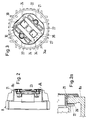
- the electromagnetic device the energization of which is a ventilation of the Brake acts against the spring force of the compression springs 19, consists of the AC magnet 24 with E-shaped magnet coil yokes 27 to the the coil 23 is placed ( Figures 2 and 3). Counter pole faces 28 to the E-shaped magnet yokes 27 are also on E-shaped Magnet yokes 29, which in a special way on the counter brake disc 17, the acts as an anchor plate 17a, are stored.
- the magnet yokes 29 ( Figures 4 and 5) are now energized AC magnets 24 ( Figures 2 and 3) on end faces 30 (Fig. 3) of the there E-shaped magnet coil yokes 27 can be aligned.
- the E-shaped magnet yokes 29 are on the anchor plate 17a, which is the resting counter-brake disc 17 forms, resiliently attached on all sides ( Figures 4 and 5).
- the magnet yokes 29 are on the anchor plate 17a underlaid with a spring element 31, which consists of a rubber element consists.
- annular sleeve 36 which elastically absorbs the axial movement of the armature plate 17a and protects against abrasion.
- the brake pads 16a, 16b which have brake pads 16 on both sides, have a plastic molded hub 15, which is provided in its guide bore 15a with the plastic toothing 1b which enables axial displacement.
- the plastic toothing 1b completely encloses a steel toothing same module (Fig. 6 and 7).
Landscapes
- Engineering & Computer Science (AREA)
- General Engineering & Computer Science (AREA)
- Mechanical Engineering (AREA)
- Physics & Mathematics (AREA)
- Electromagnetism (AREA)
- Power Engineering (AREA)
- Braking Arrangements (AREA)
- Connection Of Motors, Electrical Generators, Mechanical Devices, And The Like (AREA)
Description
- Figur 1
- einen axialen Längsschnitt durch die Bremsbaugruppe des elektrischen Antriebs,
- Figur 2
- einen axialen Längsschnitt durch das einzeln dargestellte Bremsengehäuse,
- Figur 2a
- eine Einzelheit A gemäß Figur 2 in vergrößerter Darstellung,
- Figur 3
- die zu Figur 2 gehörende Vorderansicht,
- Figur 4
- einen senkrechten Schnitt A-B gemäß Figur 5 durch die Ankerplatte des E-förmigen Magnetjoches,
- Figur 5
- eine zu Figur 4 gehörende Draufsicht auf die Ankerplatte,
- Figur 6
- einen Schnitt A - B gemäß Fig. 7 der Bremsscheibe und
- Figur 7
- eine Vorderansicht der Bremsscheibe.
Die beidseitig Bremsbeläge 16a, 16b tragende Bremsscheibe 16 weist eine aus Kunststoff angespritzte Nabe 15 auf, die in ihrer Führungsbohrung 15a mit der eine axiale Verschiebung ermöglichenden Kunststoff-Verzahnung 1b versehen ist.
- 1
- Motorwelle
- 1a
- Wellenschaft
- 1b
- Verzahnung
- 2
- Rotor
- 3
- Kurzschlußringe
- 4
- Statorwicklung
- 5
- Ständergehäuse
- 6
- Läuferlager
- 6a
- Flansch
- 7
- Wälzlager
- 8
- Bremsengehäuse
- 8a
- Bremsengehäuseboden
- 8b
- ringförmiger Absatz
- 9
- Lüfter
- 10
- Lüfterhaube
- 11
- Stehbolzen
- 12
- Gewindemutter
- 13
- Reibscheibe
- 15
- Nabe
- 15a
- Führungsbohrung
- 16
- Bremsscheibe
- 16a
- Bremsbelag
- 16b
- Bremsbelag
- 17
- Gegenbremsscheibe
- 17a
- Ankerplatte
- 17b
- Bremsfläche
- 17c
- Seite
- 18
- Führungsstifte
- 19
- Druckfedern
- 21
- Hohlniete
- 22
- Halteelement
- 23
- Spule
- 24
- Wechselstrommagnete
- 26
- Biegefeder
- 27
- E-förmige Magnetspulenjoche
- 28
- Gegenpolfläche
- 29
- Magnetjoche
- 29a
- Ausnehmungen
- 30
- Stirnflächen
- 31
- Federelement
- 32
- Stehbolzen
- 33
- Riegel
- 34
- Kunststoffgehäuse
- 34a
- Inneres des Kunststoffgehäuses
- 35
- Führungsschächte
- 36
- Ringmanschette
Claims (9)
- Elektrischer Antrieb mit Bremse, insbesondere für Hebezeuge, Hubeinrichtungen oder positionierende Förderanlagen, mit einer auf der Motorwelle axial beweglichen, durch Verzahnung mit der Motorwelle rotierenden Bremsscheibe mit beidseitigen Bremsflächen, die durch Federkraft an ruhende Gegenbremsscheiben andrückbar ist und mit einer aus Wechseistrommagneten bestehenden elektromagnetischen Einrichtung, deren Bestromung ein Lüften der Bremse entgegen der Federkraft bewirkt und bei der Gegenpolflächen an allseitig winkelbeweglichen Magnetjochen angeordnet sind, die bei Bestromung der Wechselstrommagnete an den Stimflächen der gegenüber angeordneten Magnetspulenjoche ausrichtbar sind, dadurch gekennzeichnet,
daß die Bestromung mit einphasigem Wechselstrom erfolgt und zwei getrennte, E-förmig ausgebildete Magnetspulenjoche (27) mit einer gemeinsamen, beidseitig der Motorwelle (1) angeordneten Spule (23) sowie Kurzschlußringe an den Pofflächen der Magnetspulenjoche (27) vorgesehen sind. - Elektrischer Antrieb nach Anspruch 1,
dadurch gekennzeichnet,
daß die E-förmigen Magnetjoche (29) auf einer Ankerplatte (17a) allseitig federnd befestigt sind, die eine ruhende Gegenbremsscheibe (17) bildet. - Elektrischer Antrieb nach einem der Ansprüche 1 oder 2,
dadurch gekennzeichnet,
daß die gehäuseseitigen Magnetjoche (29) mit einem Federelement (31) unterlegt sind. - Elektrischer Antrieb nach einem der Ansprüche 1 bis 3,
dadurch gekennzeichnet,
daß die zwei E-förmigen Magnetjoche (29) mittels kippbeweglichen, durch Stehbolzen (32) befestigte Riegel (33) gehalten sind, die in jeweils in dem Riegelquerschnitt entsprechende Ausnehmungen (29a) in den Magnetjochen (29) gesteckt sind, wobei sich die Magnetjoche (29) über die Federelemente (31) auf die der Bremsfläche (17b) abgewandten Seite (17c) der Ankerplatte (17a) abstützen. - Elektrischer Antrieb nach einem der Ansprüche 1 bis 4,
dadurch gekennzeichnet,
daß die um die beiden Magnetspulenjoche (27) verlaufende Wicklung (23) von einem Kunststoffgehäuse (34) umgeben ist, das in seinem Inneren (34a) Führungsschächte (35) für die E-förmigen Magnetspulenjoche (27) bildet. - Elektrischer Antrieb nach einem der Ansprüche 1 bis 5,
dadurch gekennzeichnet,
daß zwischen der Ankerplatte (17a) und einem ringförmigen Absatz (8b) des Bremsengehäuses (8) eine die Axialbewegung der Ankerplatte (17a) elastisch aufnehmende Ringmanschette (36) vorgesehen ist. - Elektrischer Antrieb nach einem der Ansprüche 1 bis 6,
dadurch gekennzeichnet,
daß die beidseitig Bremsbeläge (16a, 16b) tragende Bremsscheibe (16) eine aus Kunststoff angespritzte Nabe (15) aufweist, die in der Führungsbohrung (15a) mit einer eine axiale Verschiebung ermöglichenden Verzahnung (1b) versehen ist. - Elektrischer Antrieb nach einem der Ansprüche 1 bis 7,
dadurch gekennzeichnet,
daß die Magnetjoche (29) mit einem vorgespannten Federelement (31) unterlegt sind. - Elektrischer Antrieb nach einem der Ansprüche 1 bis 8,
dadurch gekennzeichnet,
daß die Führungsstifte (18) durch die Hohlniete (21) nach außen verlängert sind.
Applications Claiming Priority (2)
| Application Number | Priority Date | Filing Date | Title |
|---|---|---|---|
| DE4338570 | 1993-11-05 | ||
| DE4338570A DE4338570C2 (de) | 1993-11-05 | 1993-11-05 | Elektrischer Antrieb mit Bremse, insbesondere für Hebezeuge, Hubeinrichtungen oder positionierende Förderanlagen |
Publications (2)
| Publication Number | Publication Date |
|---|---|
| EP0652625A1 EP0652625A1 (de) | 1995-05-10 |
| EP0652625B1 true EP0652625B1 (de) | 1999-06-09 |
Family
ID=6502391
Family Applications (1)
| Application Number | Title | Priority Date | Filing Date |
|---|---|---|---|
| EP94250254A Expired - Lifetime EP0652625B1 (de) | 1993-11-05 | 1994-10-18 | Elektrischer Antrieb mit Bremse, insbesondere für Hebezeuge, Hubeinrichtungen oder positionierende Förderanlagen |
Country Status (4)
| Country | Link |
|---|---|
| US (1) | US5631510A (de) |
| EP (1) | EP0652625B1 (de) |
| JP (1) | JPH07135746A (de) |
| DE (2) | DE4338570C2 (de) |
Cited By (1)
| Publication number | Priority date | Publication date | Assignee | Title |
|---|---|---|---|---|
| CN105443616A (zh) * | 2015-12-31 | 2016-03-30 | 天津市灵捷传动技术有限公司 | 一种具有多功能输出端的牙嵌式电磁制动器 |
Families Citing this family (21)
| Publication number | Priority date | Publication date | Assignee | Title |
|---|---|---|---|---|
| US5814955A (en) * | 1997-03-14 | 1998-09-29 | Eaton Corporation | Motor control circuit with a low voltage monitor |
| US6211590B1 (en) * | 1997-10-02 | 2001-04-03 | Stromag, Inc. | Spring-applied pad and carrier brake |
| US6459182B1 (en) | 1998-05-14 | 2002-10-01 | Sew-Eurodrive Gmbh | Electric motor with brake |
| JP2001039642A (ja) * | 1999-08-03 | 2001-02-13 | Teijin Seiki Co Ltd | エレベータ装置 |
| DE59906401D1 (de) * | 1999-10-08 | 2003-08-28 | Osma Aufzuege Albert Schenk Gm | Antrieb für einen aufzug |
| ES2168940B1 (es) * | 2000-02-04 | 2003-11-01 | Univ Catalunya Politecnica | Mecanismo de autorregulacion del entrehierro en los sistemas de actuacion electromagnetica. |
| JP2005138367A (ja) * | 2003-11-05 | 2005-06-02 | Toshiba Mach Co Ltd | 横型多材成形機 |
| JP4525197B2 (ja) * | 2004-06-17 | 2010-08-18 | 株式会社明電舎 | エレベータ巻上機 |
| EP1627841B1 (de) * | 2004-06-19 | 2013-08-28 | Inventio AG | Antrieb für eine Aufzugsanlage |
| ZA200503649B (en) * | 2004-06-19 | 2006-02-22 | Inventio Ag | Drive for a lift installation. |
| WO2006049612A1 (en) * | 2004-11-01 | 2006-05-11 | Otis Elevator Company | Elevator disk brake with damping |
| WO2008033137A1 (en) * | 2006-09-14 | 2008-03-20 | Otis Elevator Company | Elevator brake with composite brake hub |
| US8783421B2 (en) * | 2007-09-20 | 2014-07-22 | Thyssenkrupp Aufzugswerke Gmbh | Brake device |
| US20090309082A1 (en) * | 2008-06-11 | 2009-12-17 | Warn Industries, Inc. | Fan Cooled Winch |
| CN101837938B (zh) * | 2009-12-30 | 2012-09-26 | 浙江诺和机电有限公司 | 一种单向载荷自制螺旋式制动器 |
| CN103193177A (zh) * | 2012-01-09 | 2013-07-10 | 昆山泰格林机电有限公司 | 一种曳引机制动器 |
| JP6130763B2 (ja) * | 2013-09-26 | 2017-05-17 | 株式会社日立産機システム | スクロール式流体機械およびその組み立て方法 |
| GB201513850D0 (en) | 2015-08-05 | 2015-09-16 | Renishaw Plc | Coordinate positioning machine |
| DE102016212715A1 (de) * | 2016-07-13 | 2018-01-18 | Robert Bosch Gmbh | Trägertopf für eine Bremsscheibe, Bremsscheibeneinrichtung |
| US9994425B1 (en) | 2016-12-12 | 2018-06-12 | Thyssenkrupp Elevator Ag | Compact motor arrangement with integrated brakes and shaft bearings |
| EP3372552B1 (de) * | 2017-03-10 | 2020-06-10 | Zollern GmbH & Co. KG | Elektromotor mit integrierter haltebremse |
Family Cites Families (20)
| Publication number | Priority date | Publication date | Assignee | Title |
|---|---|---|---|---|
| USRE23362E (en) * | 1951-05-01 | hallander | ||
| FR753399A (fr) * | 1932-07-21 | 1933-10-14 | Ph Bonvillain Et E Ronceray Sa | Moteur électrique perfectionné |
| US2434034A (en) * | 1944-05-29 | 1948-01-06 | Garrett Corp | Induction motor brake |
| US2461759A (en) * | 1945-02-26 | 1949-02-15 | Dumore Company | Alternating current brake motor |
| FR933189A (fr) * | 1945-09-04 | 1948-04-13 | Gen Tire & Rubber Co | Dispositif de montage élastique, en particulier pour organe de freinage |
| US2512565A (en) * | 1949-01-14 | 1950-06-20 | Star Kimble Electric Company | Spring-applied electromagnetic released brake |
| AT219162B (de) * | 1959-07-02 | 1962-01-10 | Aloys Zeppenfeld Fa | Kraftgetriebene Windeneinrichtung |
| FR1309724A (fr) * | 1962-01-08 | 1962-11-16 | Patay Moteurs | Frein électro-magnétique à disques ou à cônes |
| DE1463888B2 (de) * | 1964-12-08 | 1972-01-05 | Heemaf S.K.A. Motorenwerk AG., 4600 Dortmund; Elektromotorische Antriebe GmbH, EMA, 5800 Hagen | Bremsmotor |
| DE1303888B (de) * | 1968-09-06 | 1975-06-05 | Ausscheidung aus: 12 92 735 SEW-EURODRIVE GmbH & Co Süddeutsche Elektromotoren-Werke, 7520 Bruchsal | Bremsmotor |
| DE6926087U (de) * | 1969-07-01 | 1969-12-04 | Georgii Kobold Elektro Motoren | Befestigungsvorrichtung fuer magnetisch betaetigte bremsen |
| US3650361A (en) * | 1970-05-28 | 1972-03-21 | Gen Time Corp | Quiet operating electromagnetic clutch or brake |
| US3712426A (en) * | 1971-01-20 | 1973-01-23 | D Gilbrech | Magnetic friction brake |
| US4432446A (en) * | 1980-06-28 | 1984-02-21 | Nippondenso Co., Ltd. | Electromagnetic coupling apparatus |
| US4445596A (en) * | 1981-09-08 | 1984-05-01 | Facet Enterprises, Inc. | Electromagnetically released spring applied friction brake with torque booster and driving force distributor |
| US5233252A (en) * | 1985-11-20 | 1993-08-03 | Allied-Signal | Motor having integral detent |
| US4734604A (en) * | 1986-08-01 | 1988-03-29 | Cuisinarts, Inc. | Friction braking system and apparatus for appliance induction motor drive |
| US4921463A (en) * | 1987-10-27 | 1990-05-01 | Cummins-Allison Corporation | Coin sorter with counter and brake mechanism |
| US5036368A (en) * | 1990-12-11 | 1991-07-30 | Shinko Denki Kabushiki Kaisha | Electromagnetic coupling device |
| US5189324A (en) * | 1991-08-15 | 1993-02-23 | Hayes Axle, Inc. | Electromagnet mount for an electric brake |
-
1993
- 1993-11-05 DE DE4338570A patent/DE4338570C2/de not_active Expired - Fee Related
-
1994
- 1994-08-31 JP JP6230597A patent/JPH07135746A/ja active Pending
- 1994-10-18 DE DE59408386T patent/DE59408386D1/de not_active Expired - Fee Related
- 1994-10-18 EP EP94250254A patent/EP0652625B1/de not_active Expired - Lifetime
- 1994-11-07 US US08/335,467 patent/US5631510A/en not_active Expired - Fee Related
Cited By (1)
| Publication number | Priority date | Publication date | Assignee | Title |
|---|---|---|---|---|
| CN105443616A (zh) * | 2015-12-31 | 2016-03-30 | 天津市灵捷传动技术有限公司 | 一种具有多功能输出端的牙嵌式电磁制动器 |
Also Published As
| Publication number | Publication date |
|---|---|
| EP0652625A1 (de) | 1995-05-10 |
| JPH07135746A (ja) | 1995-05-23 |
| US5631510A (en) | 1997-05-20 |
| DE4338570A1 (de) | 1995-05-24 |
| DE4338570C2 (de) | 2000-06-08 |
| DE59408386D1 (de) | 1999-07-15 |
Similar Documents
| Publication | Publication Date | Title |
|---|---|---|
| DE4338570C2 (de) | Elektrischer Antrieb mit Bremse, insbesondere für Hebezeuge, Hubeinrichtungen oder positionierende Förderanlagen | |
| DE3036091C2 (de) | Elektromotor mit selbsttätig wirkender Bremse | |
| EP0081604B1 (de) | Eisenkernpaar und Spulenkörper für Wechselstromschütz | |
| DE1190759B (de) | Elektromotorische Verstellvorrichtung | |
| WO1999028648A1 (de) | Magnetbremse und elektromechanische bremsvorrichtung mit einer magnetbremse | |
| EP2241777B1 (de) | Flip-Flop-Kupplung | |
| EP0222312B1 (de) | Federdruckbremse | |
| DE1538801B2 (de) | Elektromotor mit einer Nutationsbewegung zwischen Rotoö und Stator. Ausscheidung in: 1788145 | |
| EP0043498B1 (de) | Elektromotor | |
| DE2620984C2 (de) | Elektrische Maschine mit Luftspaltwicklung | |
| DE3510445C2 (de) | ||
| WO1987001526A1 (fr) | Unite de regulation electrique | |
| EP0611420A1 (de) | Wartungsfreie, elektromagnetisch lüftbare federdruckbremse mit neuartiger elektrischer ansteuerungsschaltung für die magnetspule. | |
| AT408394B (de) | Vorrichtung zum abbremsen von elektromotoren | |
| WO2014108276A2 (de) | Anordnung zum verschliessen von nuten | |
| DE3901905C1 (en) | Device on the commutator of an electrical machine | |
| DE3214781C2 (de) | Elektromechanisch lüftbare Reibungsbremse | |
| DE102023114487B3 (de) | Bremseinheit für ein Fahrzeug sowie Fahrzeug | |
| DE2401846A1 (de) | Einrichtung zum selbsttaetigen abbremsen eines elektromotors | |
| EP1686281B1 (de) | Nachstellvorrichtung für eine Scheibenbremse | |
| DE2316809A1 (de) | Automatische nachstellvorrichtung fuer bremsen | |
| DE10116848A1 (de) | Elektromechanische Bremsvorrichtung | |
| DE3810155A1 (de) | Einstellvorrichtung fuer eine elektromagnet-federdruckbremse | |
| DE3005772A1 (de) | Elektromagnetische winde | |
| EP0285012A1 (de) | Einstellvorrichtung für eine Elektromagnet-Federdruckbremse |
Legal Events
| Date | Code | Title | Description |
|---|---|---|---|
| PUAI | Public reference made under article 153(3) epc to a published international application that has entered the european phase |
Free format text: ORIGINAL CODE: 0009012 |
|
| AK | Designated contracting states |
Kind code of ref document: A1 Designated state(s): DE FR GB IT |
|
| 17P | Request for examination filed |
Effective date: 19951110 |
|
| 17Q | First examination report despatched |
Effective date: 19961127 |
|
| GRAG | Despatch of communication of intention to grant |
Free format text: ORIGINAL CODE: EPIDOS AGRA |
|
| GRAG | Despatch of communication of intention to grant |
Free format text: ORIGINAL CODE: EPIDOS AGRA |
|
| GRAH | Despatch of communication of intention to grant a patent |
Free format text: ORIGINAL CODE: EPIDOS IGRA |
|
| GRAH | Despatch of communication of intention to grant a patent |
Free format text: ORIGINAL CODE: EPIDOS IGRA |
|
| GRAA | (expected) grant |
Free format text: ORIGINAL CODE: 0009210 |
|
| AK | Designated contracting states |
Kind code of ref document: B1 Designated state(s): DE FR GB IT |
|
| ET | Fr: translation filed | ||
| GBT | Gb: translation of ep patent filed (gb section 77(6)(a)/1977) |
Effective date: 19990610 |
|
| REF | Corresponds to: |
Ref document number: 59408386 Country of ref document: DE Date of ref document: 19990715 |
|
| ITF | It: translation for a ep patent filed | ||
| PLBE | No opposition filed within time limit |
Free format text: ORIGINAL CODE: 0009261 |
|
| STAA | Information on the status of an ep patent application or granted ep patent |
Free format text: STATUS: NO OPPOSITION FILED WITHIN TIME LIMIT |
|
| 26N | No opposition filed | ||
| REG | Reference to a national code |
Ref country code: GB Ref legal event code: IF02 |
|
| REG | Reference to a national code |
Ref country code: GB Ref legal event code: 732E |
|
| REG | Reference to a national code |
Ref country code: FR Ref legal event code: TP |
|
| PGFP | Annual fee paid to national office [announced via postgrant information from national office to epo] |
Ref country code: GB Payment date: 20051010 Year of fee payment: 12 |
|
| PGFP | Annual fee paid to national office [announced via postgrant information from national office to epo] |
Ref country code: FR Payment date: 20051014 Year of fee payment: 12 Ref country code: DE Payment date: 20051014 Year of fee payment: 12 |
|
| PGFP | Annual fee paid to national office [announced via postgrant information from national office to epo] |
Ref country code: IT Payment date: 20061031 Year of fee payment: 13 |
|
| PG25 | Lapsed in a contracting state [announced via postgrant information from national office to epo] |
Ref country code: DE Free format text: LAPSE BECAUSE OF NON-PAYMENT OF DUE FEES Effective date: 20070501 |
|
| GBPC | Gb: european patent ceased through non-payment of renewal fee |
Effective date: 20061018 |
|
| REG | Reference to a national code |
Ref country code: FR Ref legal event code: ST Effective date: 20070629 |
|
| PG25 | Lapsed in a contracting state [announced via postgrant information from national office to epo] |
Ref country code: GB Free format text: LAPSE BECAUSE OF NON-PAYMENT OF DUE FEES Effective date: 20061018 |
|
| PG25 | Lapsed in a contracting state [announced via postgrant information from national office to epo] |
Ref country code: FR Free format text: LAPSE BECAUSE OF NON-PAYMENT OF DUE FEES Effective date: 20061031 |
|
| PG25 | Lapsed in a contracting state [announced via postgrant information from national office to epo] |
Ref country code: IT Free format text: LAPSE BECAUSE OF NON-PAYMENT OF DUE FEES Effective date: 20071018 |