EP0652168A1 - Förderer mit schlauchförmigem Leertrum - Google Patents
Förderer mit schlauchförmigem Leertrum Download PDFInfo
- Publication number
- EP0652168A1 EP0652168A1 EP94117608A EP94117608A EP0652168A1 EP 0652168 A1 EP0652168 A1 EP 0652168A1 EP 94117608 A EP94117608 A EP 94117608A EP 94117608 A EP94117608 A EP 94117608A EP 0652168 A1 EP0652168 A1 EP 0652168A1
- Authority
- EP
- European Patent Office
- Prior art keywords
- belt
- return pipe
- recited
- hole
- pipe conveyer
- Prior art date
- Legal status (The legal status is an assumption and is not a legal conclusion. Google has not performed a legal analysis and makes no representation as to the accuracy of the status listed.)
- Withdrawn
Links
Images


Classifications
-
- B—PERFORMING OPERATIONS; TRANSPORTING
- B65—CONVEYING; PACKING; STORING; HANDLING THIN OR FILAMENTARY MATERIAL
- B65G—TRANSPORT OR STORAGE DEVICES, e.g. CONVEYORS FOR LOADING OR TIPPING, SHOP CONVEYOR SYSTEMS OR PNEUMATIC TUBE CONVEYORS
- B65G15/00—Conveyors having endless load-conveying surfaces, i.e. belts and like continuous members, to which tractive effort is transmitted by means other than endless driving elements of similar configuration
- B65G15/08—Conveyors having endless load-conveying surfaces, i.e. belts and like continuous members, to which tractive effort is transmitted by means other than endless driving elements of similar configuration the load-carrying surface being formed by a concave or tubular belt, e.g. a belt forming a trough
-
- B—PERFORMING OPERATIONS; TRANSPORTING
- B65—CONVEYING; PACKING; STORING; HANDLING THIN OR FILAMENTARY MATERIAL
- B65G—TRANSPORT OR STORAGE DEVICES, e.g. CONVEYORS FOR LOADING OR TIPPING, SHOP CONVEYOR SYSTEMS OR PNEUMATIC TUBE CONVEYORS
- B65G39/00—Rollers, e.g. drive rollers, or arrangements thereof incorporated in roller-ways or other types of mechanical conveyors
- B65G39/10—Arrangements of rollers
- B65G39/12—Arrangements of rollers mounted on framework
-
- B—PERFORMING OPERATIONS; TRANSPORTING
- B65—CONVEYING; PACKING; STORING; HANDLING THIN OR FILAMENTARY MATERIAL
- B65G—TRANSPORT OR STORAGE DEVICES, e.g. CONVEYORS FOR LOADING OR TIPPING, SHOP CONVEYOR SYSTEMS OR PNEUMATIC TUBE CONVEYORS
- B65G2201/00—Indexing codes relating to handling devices, e.g. conveyors, characterised by the type of product or load being conveyed or handled
- B65G2201/04—Bulk
Definitions
- the present invention relates to a return pipe conveyer having an endless conveyer belt which is conveyed in a flat, guided manner for the conveying trip, and in a rounded, pipe-like shape for at least a middle part of the return trip.
- the conventional return pipe conveyers shown in Figs. 5 and 6 have an endless conveyer belt 1 supported between a front roller 2 and a rear roller 3.
- the front roller 2 or the rear roller 3 is rotated with a driving means (not shown), such as a motor, to circulate the conveyer belt 1 around the rollers 2, 3.
- Multiple support frames 4 are appropriately spaced (e.g., equally spaced or staggered) in the direction of motion of the conveyer belt 1 between the rollers 2, 3, and above each support frame 4, there are multiple support rollers 5 which support the belt 1 during a conveying trip 1a of the belt 1 in a flat or slightly curved shape, while multiple shape supporting rollers 6 at the bottom part of the support frames 4 form the belt 1 into a substantially rounded or pipe-like shape during the return trip 1b.
- the conveyed object 8 is placed on the conveyer belt 1 from the supply hopper 7 during the conveying trip 1a, and then conveyed to the discharge hopper 9 where it is released.
- Multiple shape supporting rollers 6 are used for the return trip 1b of the conveyer belt 1 in order to wrap the conveying side of the belt 1 inwardly into a pipe-like shape so that portions of the conveyed object 8 which may be stuck on the surface of the conveying side of the belt 1 do not fall out of the belt.
- the belt 1 has a tendency to remain deformed in the round, pipe-like shape during the conveying trip, as shown by the dotted lines in Fig. 6, so that the sides of the belt on the conveying trip do not contact, and thus are not guided by, the supporting rollers 5. This is undesirable as it causes the belt to run unsteadily during the conveying trip.
- the object of the present invention is to supply a return pipe conveyer that eliminates the above-mentioned problems found in the conventional technology by suppressing the warping of the belt so as to supply smooth and stable action during the conveying trip.
- the present invention uses a return pipe conveyer having an endless conveyer belt supported in either a flat or curved shape by multiple support rollers each supported by a frame, the object to be conveyed being placed on top of the conveyer belt, which in the middle portion of the return trip generally uses shape supporting rollers supported on a frame causing the belt passing through to be rounded in a pipe-like shape, the sides of the belt during the conveying trip being pressed down by pressing units fixed to a support frame.
- the pressing units should be mounted on the supporting frame so that the units can be adjusted in a generally vertical direction with respect to the surface of the belt, or mounted on a supporting frame in a manner where the mounting angle is adjustable about an axis parallel with the length of the belt.
- the pressing units may include a pressing roller which rotates along the conveying side of the conveyer belt about an axis parallel with the axis of rotation of the support rollers, or they may include a support plate which moves slidably along the conveying side of the conveyer belt and which is supported by the support frame.
- the conveyer belt that is wrapped into a tube or pipe-like shape during the return trip is pressed flat by pressing units in a generally vertical direction with respect to the surface of the belt as the belt enters the conveying trip, allowing the belt to move smoothly past the supporting rollers, and providing stable conveying movement.
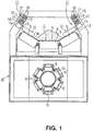
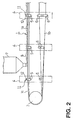
- Figs. 1 and 2 show the first embodiment of the present invention.
- parts corresponding to the conventional return pipe conveyer shown in Figs. 5 and 6 are identified by the same reference numbers, and a detailed explanation of these parts is therefore omitted.
- the first embodiment is shown in Fig. 1 where two pressing units 11 are mounted on the upper corners of one of the support frames 4 which is closest to the front roller 2, the support frame 4 surrounding the conveyer belt as it runs through the conveying trip 1a and the return trip 1b.
- the pressing units 11 press down on the sides of the conveyer belt 1 having a conveying surface 1c.
- the bearings 14 rotationally support pressing rollers 12 via members 13 along an axis which is parallel to an axis of the outermost support rollers 5.
- the bearings 14 are positioned at the bottom of brackets 15 which extend at right angles with respect to the axis of the outermost support rollers 5, and the brackets 15 are mounted on each upper corner of the support frame 4 by bolts 17 that are inserted through oblong holes 16 in each bracket 15. This allows the pressing rollers 12 to be adjusted in parallel with the axis of the support rollers 5 making it possible to press both sides of the conveyer belt 1 towards the support rollers 5.
- the sides of the belt 1 are flattened by the pressing rollers 12 against the support rollers 5 allowing the belt 1 to uniformly contact the supporting rollers for a stable and smooth conveying trip 1a.
- the mounting position of the bracket 15 can be moved toward and away from the surface of the conveyer belt 1 at the sides to accommodate conveyer belts 1 having different thicknesses.
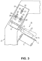
- Fig. 3 shows a second embodiment of the present invention.
- the bearing 14 rotationally supports the pressing roller 12 via member 13, the pressing roller 12 being rotatable about an axis which is parallel to the axis of the adjacent support roller 5, as in the first embodiment.
- the bearing 14 is fixed to the bottom of a bracket 21, and three oblong holes 22 are formed in the bracket 21, one in the upper middle portion and two in the lower side portions.
- One round hole 23 and one horizontally oblong hole 24 are formed vertically apart from each other in the upper side portions on the support frame 4, and one bolt 25 is inserted through the top oblong hole 22 in the bracket 21 and the round hole 23 in the support frame 4.
- two bolts 26 are inserted through the two side holes 22 in the bracket 21 and the horizontally oblong hole 24 on the supporting frame 4, and three nuts (not shown) corresponding to the three bolts 25, 26 are used to tightly secure the bracket 21 to the support frame 4.
- the position of bracket 21 and the pressing roller 12 can be adjusted to move toward and away from the surface of the conveying web, as in the first embodiment.
- the bracket 21 and the supported pressing roller 12 can be rotated about the top hole 23 and bolt 25, as shown by the solid and dotted lines in Fig. 3, so that the mounting angle of the bracket 21 and the pressing roller 12 is adjustable about an axis parallel to the length of conveyer belt.
- the tilting angle of the outermost support roller 5 is slightly changed, the mounting angle of the bracket 21 and the pressing roller 12 can be adjusted to accommodate the change in the tilting angle of the support roller 5.
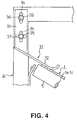
- Fig. 4 shows a third embodiment of the present invention.
- a pressing unit 31 is supported by the support frame 4 and includes a pressing plate 32 which moves slidably along the sides 1a of the conveyer belt 1 adjacent the support rollers 5.
- the pressing plate 32 is made of, for example, a synthetic resin with a low friction coefficient and may be a single unit including the bracket 33 which has a pair of vertically oblong holes 34 in the center. Two bolts 35 are inserted through each oblong hole 34 and then through a round hole 36 and a horizontal oblong hole 37, respectively, on the support frame 4. Nuts (not shown) are secured to each bolt 35, thereby fixing the bracket 33 and the pressing plate 32 to the support frame 4 so that the mounting position can be adjusted vertically, as well as at an angle about an axis parallel to the length of the conveyer belt 1.
- the third embodiment has the same advantages as the first and second embodiments.
- the bracket of the third embodiment is very simple and easy to produce, and if the pressing plate 32 is made of an elastic material, the pressing plate 32 will press down on the conveyer belt 1 with an appropriate pressure. Further, if the conveyer belt 1 is warped, or if a portion of the conveyer belt having an object to be conveyed is stuck to the conveyer surface 1c, the pressing plate 32 will bend elastically to let the obstruction pass through, thereby preventing damage to the pressing plate 32, the conveyer belt 1, the supporting rollers 5, etc.
- the rounded and warped portion of the conveyer belt caused during the return trip is pressed by a pressing unit mounted along the sides of the conveyer belt so that the edge portions of the belt uniformly contact the supporting rollers, thereby causing the belt to move in a stable and smooth manner during the conveying trip.
- the present invention prevents warping and unstable running of the conventional belt caused when the edges of the belt remain deformed after the return trip.
Landscapes
- Engineering & Computer Science (AREA)
- Mechanical Engineering (AREA)
- Structure Of Belt Conveyors (AREA)
- Rollers For Roller Conveyors For Transfer (AREA)
Applications Claiming Priority (2)
| Application Number | Priority Date | Filing Date | Title |
|---|---|---|---|
| JP5279387A JPH07133009A (ja) | 1993-11-09 | 1993-11-09 | リターンパイプコンベヤ |
| JP279387/93 | 1993-11-09 |
Publications (1)
| Publication Number | Publication Date |
|---|---|
| EP0652168A1 true EP0652168A1 (de) | 1995-05-10 |
Family
ID=17610431
Family Applications (1)
| Application Number | Title | Priority Date | Filing Date |
|---|---|---|---|
| EP94117608A Withdrawn EP0652168A1 (de) | 1993-11-09 | 1994-11-08 | Förderer mit schlauchförmigem Leertrum |
Country Status (4)
| Country | Link |
|---|---|
| EP (1) | EP0652168A1 (de) |
| JP (1) | JPH07133009A (de) |
| CN (1) | CN1107117A (de) |
| CA (1) | CA2135001A1 (de) |
Cited By (3)
| Publication number | Priority date | Publication date | Assignee | Title |
|---|---|---|---|---|
| DE19821514A1 (de) * | 1998-05-13 | 1999-11-25 | Svedala Ind Deutschland Gmbh | Führungsrolleneinheit für Steilförderer |
| CN102951424A (zh) * | 2011-08-31 | 2013-03-06 | 南京梅山冶金发展有限公司 | 一种管状皮带机的强力张开装置 |
| DE102014218443A1 (de) * | 2014-09-15 | 2016-03-17 | Phoenix Conveyor Belt Systems Gmbh | Förderanlage |
Families Citing this family (7)
| Publication number | Priority date | Publication date | Assignee | Title |
|---|---|---|---|---|
| CN102774628A (zh) * | 2012-07-19 | 2012-11-14 | 北京约基同力机械制造有限公司 | 可双向运料的组合型带式输送机 |
| CN102849430A (zh) * | 2012-08-17 | 2013-01-02 | 无锡杰思物流设备有限公司 | 托辊组件的安装结构 |
| CN102815492B (zh) * | 2012-08-31 | 2016-06-29 | 金福民 | 一种传输稳定的带式输送机 |
| CN103010702A (zh) * | 2012-12-05 | 2013-04-03 | 江苏永钢集团有限公司 | 管带机防跑偏扭转装置 |
| CN104030001B (zh) * | 2014-06-19 | 2016-04-06 | 国网四川省电力公司成都市新都供电分公司 | 用于支承带式输送机中传输带的结构 |
| CN104555330B (zh) * | 2015-01-06 | 2017-01-25 | 北京雨润华科技开发有限公司 | 一种多动力夹带驱动带式输送机 |
| CN110395530B (zh) * | 2019-08-06 | 2020-12-04 | 平湖市伊凡家箱包有限公司 | 一种可调节传送带角度的机构 |
Citations (7)
| Publication number | Priority date | Publication date | Assignee | Title |
|---|---|---|---|---|
| DE633729C (de) * | 1932-06-07 | 1936-08-05 | Flottmann Akt Ges | Foerderrutsche |
| GB821370A (en) * | 1957-04-11 | 1959-10-07 | Percival James Packman | Improvements in tracking means for conveyer bands and belts |
| DE1189896B (de) * | 1963-01-11 | 1965-03-25 | Rieter Ag Maschf | Foerderband zum Transport von Faserbaendern |
| JPS59149211A (ja) * | 1983-02-16 | 1984-08-27 | Kunio Hashimoto | 復路ベルトの付着物落下を防止したベルトコンベヤ |
| JPS6256203A (ja) * | 1985-09-05 | 1987-03-11 | Haruo Okazaki | パイプコンベアの湾曲部における搬送ベルトの回走方法 |
| EP0301454A1 (de) * | 1987-07-30 | 1989-02-01 | Bridgestone Corporation | Feststellung und Korrektur der Verdrehung eines Schlauchbandes |
| WO1991009795A1 (de) * | 1989-12-29 | 1991-07-11 | Vsr Engineering Gmbh Fördertechnik | Rolleneinrichtung für schlauchgurtförderer und dergleichen |
-
1993
- 1993-11-09 JP JP5279387A patent/JPH07133009A/ja active Pending
-
1994
- 1994-11-03 CA CA 2135001 patent/CA2135001A1/en not_active Abandoned
- 1994-11-08 EP EP94117608A patent/EP0652168A1/de not_active Withdrawn
- 1994-11-09 CN CN 94119646 patent/CN1107117A/zh active Pending
Patent Citations (7)
| Publication number | Priority date | Publication date | Assignee | Title |
|---|---|---|---|---|
| DE633729C (de) * | 1932-06-07 | 1936-08-05 | Flottmann Akt Ges | Foerderrutsche |
| GB821370A (en) * | 1957-04-11 | 1959-10-07 | Percival James Packman | Improvements in tracking means for conveyer bands and belts |
| DE1189896B (de) * | 1963-01-11 | 1965-03-25 | Rieter Ag Maschf | Foerderband zum Transport von Faserbaendern |
| JPS59149211A (ja) * | 1983-02-16 | 1984-08-27 | Kunio Hashimoto | 復路ベルトの付着物落下を防止したベルトコンベヤ |
| JPS6256203A (ja) * | 1985-09-05 | 1987-03-11 | Haruo Okazaki | パイプコンベアの湾曲部における搬送ベルトの回走方法 |
| EP0301454A1 (de) * | 1987-07-30 | 1989-02-01 | Bridgestone Corporation | Feststellung und Korrektur der Verdrehung eines Schlauchbandes |
| WO1991009795A1 (de) * | 1989-12-29 | 1991-07-11 | Vsr Engineering Gmbh Fördertechnik | Rolleneinrichtung für schlauchgurtförderer und dergleichen |
Non-Patent Citations (2)
| Title |
|---|
| PATENT ABSTRACTS OF JAPAN vol. 11, no. 247 (M - 615)<2694> 12 August 1987 (1987-08-12) * |
| PATENT ABSTRACTS OF JAPAN vol. 8, no. 280 (M - 347)<1717> 21 December 1984 (1984-12-21) * |
Cited By (4)
| Publication number | Priority date | Publication date | Assignee | Title |
|---|---|---|---|---|
| DE19821514A1 (de) * | 1998-05-13 | 1999-11-25 | Svedala Ind Deutschland Gmbh | Führungsrolleneinheit für Steilförderer |
| DE19821514C2 (de) * | 1998-05-13 | 2003-06-26 | Mesto Minerals Moers Gmbh | Führungsrolleneinheit für Steilförderer |
| CN102951424A (zh) * | 2011-08-31 | 2013-03-06 | 南京梅山冶金发展有限公司 | 一种管状皮带机的强力张开装置 |
| DE102014218443A1 (de) * | 2014-09-15 | 2016-03-17 | Phoenix Conveyor Belt Systems Gmbh | Förderanlage |
Also Published As
| Publication number | Publication date |
|---|---|
| CA2135001A1 (en) | 1995-05-10 |
| CN1107117A (zh) | 1995-08-23 |
| JPH07133009A (ja) | 1995-05-23 |
Similar Documents
| Publication | Publication Date | Title |
|---|---|---|
| EP0652168A1 (de) | Förderer mit schlauchförmigem Leertrum | |
| US7347319B2 (en) | Tilting roller | |
| CN214421531U (zh) | 一种便于调节高度的皮带机 | |
| US5409207A (en) | Stacking of flexible planar articles | |
| JPH09175627A (ja) | カーブコンベヤ用のトラフ形ローラ | |
| JPH09156741A (ja) | コンベアベルト支持装置 | |
| CN211225143U (zh) | 一种自动化生产线用传送装置 | |
| JP2618733B2 (ja) | ベルト案内装置付きカーブコンベヤ | |
| JP4826734B2 (ja) | カーブコンベア装置 | |
| CN218987779U (zh) | 一种带式输送机自移机尾用传输装置 | |
| KR100815800B1 (ko) | 벨트 컨베이어의 사행조정장치 | |
| JPH0141698Y2 (de) | ||
| EP0549833A1 (de) | Doppelbandfördervorrichtung | |
| US5499709A (en) | Conveyor with separator/aligner | |
| KR102463286B1 (ko) | 연속식 하역기용 이송 가이드장치 | |
| KR0123910Y1 (ko) | 벨트 콘베이어의 벨트위치 제어장치 | |
| JP3539989B2 (ja) | 搬送装置 | |
| KR101482277B1 (ko) | 벨트 컨베이어에 구비되는 벨트 지지 장치 | |
| CN216140774U (zh) | 一种输送带防跑偏及承托装置 | |
| MXPA05001558A (es) | N-aril-2-oxazolidinonas y sus derivados. | |
| KR0127102Y1 (ko) | 밸트사행 조정장치 | |
| JPH0730218U (ja) | 乾燥施設等における横送りチェンコンベヤ装置 | |
| KR19980028561U (ko) | 컨베이어의 벨트 사행조정장치 | |
| JPH0221452Y2 (de) | ||
| JPS6026518A (ja) | ベルトコンベヤのベルト自動調心装置 |
Legal Events
| Date | Code | Title | Description |
|---|---|---|---|
| PUAI | Public reference made under article 153(3) epc to a published international application that has entered the european phase |
Free format text: ORIGINAL CODE: 0009012 |
|
| AK | Designated contracting states |
Kind code of ref document: A1 Designated state(s): GB IT |
|
| STAA | Information on the status of an ep patent application or granted ep patent |
Free format text: STATUS: THE APPLICATION HAS BEEN WITHDRAWN |
|
| 18W | Application withdrawn |
Withdrawal date: 19950913 |