EP0651232B2 - Drehkodierer - Google Patents
Drehkodierer Download PDFInfo
- Publication number
- EP0651232B2 EP0651232B2 EP94117027A EP94117027A EP0651232B2 EP 0651232 B2 EP0651232 B2 EP 0651232B2 EP 94117027 A EP94117027 A EP 94117027A EP 94117027 A EP94117027 A EP 94117027A EP 0651232 B2 EP0651232 B2 EP 0651232B2
- Authority
- EP
- European Patent Office
- Prior art keywords
- diffraction grating
- light
- diffraction
- radial
- grating
- Prior art date
- Legal status (The legal status is an assumption and is not a legal conclusion. Google has not performed a legal analysis and makes no representation as to the accuracy of the status listed.)
- Expired - Lifetime
Links
- 239000013598 vector Substances 0.000 claims description 7
- 238000005259 measurement Methods 0.000 claims description 3
- 239000011295 pitch Substances 0.000 description 21
- 230000003287 optical effect Effects 0.000 description 18
- 238000010276 construction Methods 0.000 description 12
- 230000000737 periodic effect Effects 0.000 description 8
- 230000001678 irradiating effect Effects 0.000 description 7
- 230000001419 dependent effect Effects 0.000 description 2
- 238000010586 diagram Methods 0.000 description 2
- 230000007613 environmental effect Effects 0.000 description 2
- NCGICGYLBXGBGN-UHFFFAOYSA-N 3-morpholin-4-yl-1-oxa-3-azonia-2-azanidacyclopent-3-en-5-imine;hydrochloride Chemical compound Cl.[N-]1OC(=N)C=[N+]1N1CCOCC1 NCGICGYLBXGBGN-UHFFFAOYSA-N 0.000 description 1
- 229920000535 Tan II Polymers 0.000 description 1
- 230000005540 biological transmission Effects 0.000 description 1
- 230000001427 coherent effect Effects 0.000 description 1
- 230000000052 comparative effect Effects 0.000 description 1
- 238000001514 detection method Methods 0.000 description 1
- 238000011161 development Methods 0.000 description 1
- 230000018109 developmental process Effects 0.000 description 1
- 238000006073 displacement reaction Methods 0.000 description 1
- 238000012544 monitoring process Methods 0.000 description 1
- 230000002194 synthesizing effect Effects 0.000 description 1
Images


Classifications
-
- G—PHYSICS
- G01—MEASURING; TESTING
- G01D—MEASURING NOT SPECIALLY ADAPTED FOR A SPECIFIC VARIABLE; ARRANGEMENTS FOR MEASURING TWO OR MORE VARIABLES NOT COVERED IN A SINGLE OTHER SUBCLASS; TARIFF METERING APPARATUS; MEASURING OR TESTING NOT OTHERWISE PROVIDED FOR
- G01D5/00—Mechanical means for transferring the output of a sensing member; Means for converting the output of a sensing member to another variable where the form or nature of the sensing member does not constrain the means for converting; Transducers not specially adapted for a specific variable
- G01D5/26—Mechanical means for transferring the output of a sensing member; Means for converting the output of a sensing member to another variable where the form or nature of the sensing member does not constrain the means for converting; Transducers not specially adapted for a specific variable characterised by optical transfer means, i.e. using infrared, visible, or ultraviolet light
- G01D5/32—Mechanical means for transferring the output of a sensing member; Means for converting the output of a sensing member to another variable where the form or nature of the sensing member does not constrain the means for converting; Transducers not specially adapted for a specific variable characterised by optical transfer means, i.e. using infrared, visible, or ultraviolet light with attenuation or whole or partial obturation of beams of light
- G01D5/34—Mechanical means for transferring the output of a sensing member; Means for converting the output of a sensing member to another variable where the form or nature of the sensing member does not constrain the means for converting; Transducers not specially adapted for a specific variable characterised by optical transfer means, i.e. using infrared, visible, or ultraviolet light with attenuation or whole or partial obturation of beams of light the beams of light being detected by photocells
- G01D5/36—Forming the light into pulses
- G01D5/38—Forming the light into pulses by diffraction gratings
-
- G—PHYSICS
- G01—MEASURING; TESTING
- G01P—MEASURING LINEAR OR ANGULAR SPEED, ACCELERATION, DECELERATION, OR SHOCK; INDICATING PRESENCE, ABSENCE, OR DIRECTION, OF MOVEMENT
- G01P3/00—Measuring linear or angular speed; Measuring differences of linear or angular speeds
- G01P3/36—Devices characterised by the use of optical means, e.g. using infrared, visible, or ultraviolet light
- G01P3/366—Devices characterised by the use of optical means, e.g. using infrared, visible, or ultraviolet light by using diffraction of light
-
- G—PHYSICS
- G01—MEASURING; TESTING
- G01P—MEASURING LINEAR OR ANGULAR SPEED, ACCELERATION, DECELERATION, OR SHOCK; INDICATING PRESENCE, ABSENCE, OR DIRECTION, OF MOVEMENT
- G01P3/00—Measuring linear or angular speed; Measuring differences of linear or angular speeds
- G01P3/42—Devices characterised by the use of electric or magnetic means
- G01P3/44—Devices characterised by the use of electric or magnetic means for measuring angular speed
- G01P3/48—Devices characterised by the use of electric or magnetic means for measuring angular speed by measuring frequency of generated current or voltage
- G01P3/481—Devices characterised by the use of electric or magnetic means for measuring angular speed by measuring frequency of generated current or voltage of pulse signals
- G01P3/486—Devices characterised by the use of electric or magnetic means for measuring angular speed by measuring frequency of generated current or voltage of pulse signals delivered by photo-electric detectors
Definitions
- the invention relates to a rotary encoder and, more particularly, to a rotary encoder suitable for measuring a rotational speed, a rotational displacement, or the like of a rotary object such that when a laser beam or a light beam from a laser diode, an LED, or the like enters a radial diffraction grating of a disk attached to a rotary object (scale), a diffraction light of a predetermined order from the radial diffraction grating is subjected to a phase modulating function according to the rotational speed or rotational direction of the disk.
- a rotary encoder as a measuring instrument which can measure rotational information such as rotational amount, rotating direction, or the like of a rotary object in an NC machine tool or the like at a high precision, for example, on a submicron unit basis.
- Such a rotary encoder is used in various fields.
- a rotary encoder of the diffraction light interference system such that a coherent light beam such as a laser beam or the like enters a diffraction grating provided for a moving object, diffraction lights of predetermined orders generated from the diffraction grating are mutually interfered, and the number of bright and dark portions of the resultant interference fringe is counted, thereby obtaining a moving state such as movement amount, movement information, or the like of the moving object.
- This object is achieved by the apparatus of claim 1.
- Advantageous further developments are as set out in the dependent claims.
- Fig. 1 is a perspective view of a main section of an embodiment.
- a light beam R radiated from a light emitting device (light source) 1 such as laser diode, light emitting diode, or the like is converted to a parallel light through an optical system (not shown) and is irradiated to a point P1 on a diffraction grating G1 comprising a linear grating.
- a light emitting device (light source) 1 such as laser diode, light emitting diode, or the like is converted to a parallel light through an optical system (not shown) and is irradiated to a point P1 on a diffraction grating G1 comprising a linear grating.
- a +1st order diffracted light R +1 and a 0th-order diffraction light R 0 are allowed to enter points P2a and P2b on a radial diffraction grating G2 on a disk 4 coupled to a rotary object (not shown) which rotates around a rotary axis Da as a rotational center as shown by an arrow Ya.
- a light beam R +1 -1 which was -1st order diffracted at the point P2a of the radial diffraction grating G2 is allowed to enter a point P3a on a diffraction grating G3 comprising a linear grating.
- a light beam R 0 +1 which was +1st order diffracted at the point P2b of the radial diffraction grating G2 is allowed to enter a point P3b on the diffraction grating G3.
- arranging azimuths (arranging directions of the gratings) of the gratings at the points P3a and P3b are set so as to be parallel with an arranging azimuth of the grating of the diffraction grating G1.
- the arranging azimuths of the gratings of the diffraction gratings G1 and G3 are set so as to be parallel with the arranging azimuth at the irradiating point P2a of the radial diffraction grating G2.
- the diffraction gratings G1 and G3 are constructed by linear gratings on the same board surface.
- the point P1 and the points P3a, P3b are set so as to be located at different positions of the linear gratings on the same board surface.
- a light beam R 0 +1 -1 which was -1st order diffracted at the point P3b of the diffraction grating G3 is extracted from the diffraction grating G3 in the direction perpendicular to the disk surface. That is, in the embodiment, the light beams R +1 -1 0 and R 0 +1 -1 are taken out from the diffraction grating G3 with an angle therebetween. Optical paths of the light beams R +1 -1 0 and R 0 +1 -1 are partially overlapped and interfered and are led to a photosensitive device 6.
- a sine-wave-like signal light (interference signal) based on the bright and dark portions of an interference pattern at this time is obtained by the photosensitive device 6.
- Rotational information of the disk 4 is obtained by using an interference signal from the photosensitive device 6.
- the photosensitive device 6 is constructed so that a photosensitive surface 6a has an array shape of the same pitch as that of an interference fringe which is formed on the surface of the photosensitive device.
- the photosensitive surface of the photosensitive device is set to a rectangular shape whose width is narrower than the width of the interference fringe pitch and is arranged in an array shape so as to have a pitch P that is specified by the following equation.
- the embodiment has the following features.
- Figs. 2 to 5 are perspective views of main sections according to embodiments 2 to 5, respectively.
- the embodiment 2 of Fig. 2 differs from the embodiment 1 of Fig. 1 with respect to a point that the arranging azimuths of the diffraction gratings G1 and G2 are set to be parallel with the arranging azimuth at the irradiating point P2b of the radial diffraction grating G2, thereby generating an interference fringe pattern of the interference signal light.
- the other constructions are similar to Fig. 1.
- the diffraction grating G1 is arranged so as to be parallel with either one of the arranging azimuths at the irradiating points P2a and P2b on the radial diffraction grating G2 on the rotary disk 4.
- the embodiment 3 of Fig. 3 differs from the embodiment 1 of Fig. 1 with respect to a point that the diffraction grating G1 is arranged so as to have an angular difference in the opposite direction for both of the arranging azimuths at the irradiating points P2a and P2b on the radial diffraction grating G2 on the rotary disk, namely, so as to be almost parallel with the arranging azimuth of the diffraction grating G2 at the middle point of the points P2a and P2b.
- the other constructions are similar to Fig. 1.
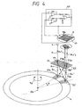
- the embodiment 4 of Fig. 4 differs from the embodiment 1 of Fig. 1 with respect to a point that the photosensitive device 6 is constructed by two comb-shaped photosensitive surfaces 6a and 6b which are mated with each other and have the same pitch as that of the interference fringe formed on the surface of the photosensitive device 6 and that a difference between the output signals derived from the two photosensitive surfaces 6a and 6b is extracted by a differential amplifying circuit AM and is outputted.
- the other constructions are similar to the embodiment 1.
- the embodiment has the following features.
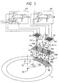
- the embodiment 5 of Fig. 5 has a construction such that similar diffraction gratings and photosensitive devices are symmetrically arranged around an optical path Rs of the light beam R from the light emitting device 1 in the embodiment 4 of Fig. 4. Namely, three light beams are irradiated onto the diffraction grating G2, thereby forming interference signals on both sides of the optical path Rs.
- the light beam R emitted from the light emitting device 1 is irradiated to the point P1 on the diffraction grating G1.
- the three light beams of the 0-th order diffraction light R 0 , +1st order diffracted light R +1 , and -1st order diffracted light R -1 which are caused by the light irradiation are respectively irradiated to the points P2a, P2b, and P2c on the radial grating G2 recorded on the disk 4.
- the light beam R 0 +1 which was +1st order diffracted at the point P2b is irradiated to the point P3b on the diffraction grating G3a.
- the light beam R +1 -1 which was -1st order diffracted at the point P2a is irradiated to the point P3a on the diffraction grating G3a.
- a light beam R -1 +1 which was +1st order diffracted at the point P2c is irradiated to a point P3c on the diffraction grating G3b.
- a light beam R 0 -1 which was -1st order diffracted at the point P2b is irradiated to a point P3d on the diffraction grating G3b.
- Those electrical periodic signals are sine-wave-like signals of two periods when the disk 4 is rotated by an angle corresponding to one pitch of the radial diffraction grating.
- the interference signal light is obtained from two positions of the diffraction grating G1
- the phases of the grating arrangement between the diffraction gratings G3a and G3b are deviated by 1/4 pitch between (point P3a, point P3b) and (point P3c, point P3d) as shown in Fig. 5
- the phases of the bright and dark portions of the interference lights entering the photosensitive devices 6a and 6b can be deviated by 90°.
- Figs. 6 to 9 are perspective views of main sections of embodiments 6 to 9 according to the invention.
- the embodiments 6 to 9 differ from the embodiment 1 of Fig. 1 mainly with respect to points that the light beams enter the points P3a and P3b of the diffraction grating G3 and the light beam diffracted at the point P3a and the light beam diffracted at the point P3b are extracted so as to be parallel with each other and both of the light beams are overlapped to thereby form an interference fringe and that a photosensitive device comprising a single photosensitive surface is used as a photosensitive device 6.
- the other constructions are similar to the embodiment 1.
- the light beam R emitted from the light emitting device (light source) 1 such as laser diode, light emitting diode, or the like is converted to the parallel light via an optical system (not shown) and is irradiated onto the point P1 on the diffraction grating G1 comprising the linear grating.
- the +1st order diffracted light R +1 and the 0-th order diffraction light R 0 among a plurality of diffraction lights diffracted by the diffraction grating G1 are allowed to enter the points P2a and P2b on the radial diffraction grating G2 on the disk 4 coupled to a rotary object (not shown) which rotates around the rotary axis Da as a rotational center as shown by the arrow Ya.
- the light beam R +1 -1 which was -1st order diffracted at the point P2a of the radial diffraction grating G2 is allowed to enter the point P3a on the diffraction grating G3 comprising the linear grating.
- the light beam R 0 +1 which was +1st order diffracted at the point P2b of the radial diffraction grating G2 is allowed to enter the point P3b on the diffraction grating G3.
- the pitches of the diffraction gratings at the points P1 and P2 are equalized.
- the pitches of the diffraction gratings at the points P2a and P3b are equalized.
- the diffraction grating G3 is set so as to have a proper angle difference ⁇ between the arranging azimuths of the gratings of the diffraction grating G3 at the points P3a and P3b and the arranging azimuth of the grating of the diffraction grating G1.
- An outgoing azimuth vector of the light beam R +1 -1 0 which was 0-th order diffracted at the point P3a of the diffraction grating G3 is made coincide with an outgoing azimuth vector of the light beam R 0 +1 -1 which was -1st order diffracted at the point P3b of the diffraction grating G3.
- Both of the light beams are overlapped to thereby interfere with each other.
- the interference light is led to the photosensitive device 6.
- the photosensitive device 6 generates a sine-wave-like signal light based on the bright and dark portions of the interference pattern produced in this instance.
- a signal processing circuit (not shown) obtains rotational information of the disk 4 by using the signal light.
- the sine wave signal of two periods is derived as an electrical periodic signal from the photosensitive device 6.
- the embodiment has been shown with respect to the case where the reflected diffraction light by the diffraction grating G2 on the disk 4 is used and the diffraction gratings G1 and G3 are arranged on the same side.
- the diffraction gratings G1 and G3 can be also arranged so as to face both sides of the diffraction grating G2.
- the arranging azimuths of the diffraction gratings at the points P3a and P3b on the diffraction grating G3 and at the point P1 on the diffraction grating G1 are set so as to have the proper angle ⁇ , so that the two overlapped light beams from the diffraction grating G3 are made parallel with each other and a uniform interference light beam is derived. Consequently, a periodic signal of a good S/N ratio can be obtained from the photosensitive device.
- the rotational information of the disk 4 can be detected at a high precision.
- the embodiment has the following advantages.
- the embodiment 7 of Fig. 7 differs from the embodiment 6 of Fig. 6 with respect to a point that the radial diffraction gratings are used as diffraction gratings G1 and G3.
- the other constructions are similar to the embodiment 6.
- the light beam R emitted from the light emitting device (light source) 1 such as laser diode, light emitting diode, or the like is converted to the parallel light through an optical system (not shown) and is irradiated to the point P1 on the radial diffraction grating G1.
- the +1st order diffracted light R +1 and the 0-th order diffraction light R 0 among a plurality of diffraction lights diffracted by the radial diffraction grating G1 are allowed to enter the points P2a and P2b on the radial diffraction grating G2 on the disk 4 coupled with a rotary object (not shown) which rotates around the rotary axis Da as a rotational center as shown by the arrow Ya.
- the light beam R +1 -1 which was -1st order diffracted at the point P2a of the radial diffraction grating G2 is allowed to enter the point P3a on the radial diffraction grating G3.
- the light beam R 0 +1 which was +1st order diffracted at the point P2b on the radial diffraction grating G2 is allowed to enter the point P3b on the radial diffraction grating G3.
- the centers of the radial diffraction gratings G1, G2, and G3 are made coincide and, further, the numbers N of gratings in the case where they are calculated as a whole circumference are equalized.
- an outgoing azimuth vector of the light beam R +1 -1 0 which was 0-th order diffracted at the point P3a of the diffraction grating G3 is made coincide with an outgoing azimuth vector of the light beam R 0 +1 -1 which was -1st order diffracted at the point P3b of the diffraction grating G3.
- Both of the light beams are overlapped to thereby interfere with each other.
- the interference light is led to the photosensitive device 6.
- the photosensitive device 6 generates a sine-wave-like signal light based on the bright and dark portions of an interference pattern produced in this instance.
- a signal processing circuit (not shown) obtains rotational information of the disk 4 by using the signal light.
- a sine-wave-like signal of two periods is derived from the photosensitive device 6.
- the embodiment has the following features.
- the embodiment 8 of Fig. 8 differs from the embodiment 6 of Fig. 6 with respect to a point that the diffraction gratings G1 and G3 comprising the linear gratings are arranged with an angle ⁇ so as to be parallel with each other for the grating arranging azimuths at the positions P2a and P2b on the radial diffraction grating G2 on the rotary disk 4.
- the other constructions are similar to the embodiment 6.
- the light beam R emitted from the light emitting device (light source) 1 such as laser diode, light emitting diode, or the like is converted to the parallel beam through an optical system (not shown) and is irradiated to the point P1 on the diffraction grating G1 comprising the linear grating.
- the +1st order diffracted light R +1 and the 0-th order diffraction light R 0 among a plurality of diffraction lights diffracted by the diffraction grating G1 are allowed to enter the points P2a and P2b on the radial diffraction grating G2 on the disk 4 coupled with a rotary object (not shown) which rotates around the rotary axis Da as a rotational center as shown by the arrow Ya.
- the light beam R +1 -1 which was -1st order diffracted at the point P2a of the radial diffraction grating G2 is allowed to enter the point P3a on the diffraction grating G3 comprising the linear grating.
- the light beam R 0 +1 which was +1st order diffracted at the point P2b of the radial diffraction grating G2 is allowed to enter the point P3b on the diffraction grating G3.
- the arranging azimuth of the grating of the radial diffraction grating G2 at the point P2a is parallel with that of the diffraction grating G1 comprising the linear grating and has the same pitch.
- the arranging azimuth of the grating of the radial diffraction grating G2 at the point P2b is parallel with that of the diffraction grating G3 comprising the linear grating and has the same pitch.
- Both of the light beams are overlapped to thereby interfere with each other.
- the interference light is led to the photosensitive device 6.
- the photosensitive device 6 generates a sine-wave-like signal light based on the bright and dark portions of the interference pattern in this instance.
- a signal processing circuit (not shown) obtains rotational information of the disk 4 by using the signal light.
- the sine-wave-like signal of two periods is obtained from the photosensitive device 6 in a manner similar to the embodiment 6.
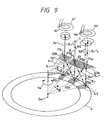
- the embodiment 9 of Fig. 9 has a construction such that the optical path Rs of the light beam R from the light emitting device 1 in the embodiment 7 of Fig. 7 is made symmetrical and similar radial diffraction gratings and photosensitive devices are arranged on both sides. That is, three light beams are irradiated onto the diffraction grating G2, thereby forming interference signals on both sides of the optical path Rs.
- the light beam R emitted from the light emitting device 1 is irradiated to the point P1 on the radial diffraction grating G1.
- Three light beams of the 0-th order diffraction light R 0 , +1st order diffracted light R +1 , and -1st order diffracted light R -1 produced by the light irradiation are irradiated to the points P2a, P2b, and P2c on the radial diffraction grating G2 recorded on the disk 4, respectively.
- the light beam R 0 +1 which was +1st order diffracted at the point P2b is irradiated to the point P3b on the radial diffraction grating G3a.
- the light beam R +1 -1 which was -1st order diffracted at the point P2a is irradiated to the point P3a on the radial diffraction grating G3a.
- the light beam R -1 +1 which was +1st order diffracted at the point P2c is irradiated to the point P3c on the radial diffraction grating G3b.
- the light beam R 0 +1 which was -1st order diffracted at the point P2b is irradiated to the point P3d on the radial diffraction grating G3b.
- the centers of the radial diffraction gratings G1, G3a, and G3b at the points P3a, P3b, P3c, and P3d are made coincide and the numbers of gratings when they are calculated as a whole circumference are equalized.
- the every two light beams of both sides are emitted in parallel with each other.
- the interference signal lights are received by photosensitive devices 6X and 6Y, so that electrical periodic signals are generated therefrom.
- Those electrical periodic signals are sine-wave-like signals of two periods when the disk 4 rotates by an angle corresponding to one pitch of the radial diffraction grating.
- the embodiment has the following features.
- the diffraction order numbers of the diffraction lights are not limited to 0, +1st, and -1st but any other orders can be also used.
- photosensitive devices it is also possible to construct in a manner such that two sets of photoelectric devices comprising comb-shaped photosensitive surfaces which are in engagement with each other are arranged so as to be neighboring and the phases are mutually deviated and signals of four phases which are deviated by 90° from each other are generated.
- the disk having fine gratings comprising diffraction gratings (radial gratings) of small diameters and a high density is used and two diffraction lights of predetermined orders which are obtained when the light beam is irradiated to the fine gratings are mutually properly interfered.
- a rotary encoder which can detect rotational information of a rotary object (disk) at a high resolution while realizing the small and thin size of the whole apparatus.
Claims (10)
- Gerät zur Erfassung relativer Rotationsinformationen mit einem zu messenden Objekt mit einem radialen Beugungsgitter (G2), mit:einer Lichtquelle (1) zum Emittieren eines Lichtstrahls für eine Messung,einem Zerlegungsbeugungsgitter (G1) zur Zerlegung des Lichtstrahls für eine Messung in eine Vielzahl von Lichtstrahlen,einem Mischbeugungsgitter (G3) zum Mischen zumindest eines Satzes von Beugungslichtern aus einer Vielzahl von Beugungslichtern, die erzeugt werden, wenn die Vielzahl von Lichtstrahlen von dem radialen Gitter (G2) gebeugt wird, wodurch zumindest ein Interferenzlichtstrahl ausgebildet wird, undeinem Erfassungsabschnitt (6) zum Erfassen des zumindest einen Interferenzlichtstrahls und zum Erzeugen eines Signals, das die relative Rotationsinformation des zu messenden Objekts betrifft, wobei der Erfassungsabschnitt (6) einen Lichtempfangsbereich aufweist,wobei zumindest eines des Zerlegungsbeugungsgitters (G1), des Mischbeugungsgitters (G3) und des Lichtempfangsbereichs so konfiguriert ist, das Phasen von Interferenzlichtkomponenten des zumindest einen auf den Lichtempfangsbereich auftreffenden Interferenzlichtstrahls im Wesentlichen miteinander zusammenfallen, wobei die Konfiguration eine Anordnung des Gitterlinienanordnungsazimut zumindest eines des Zerlegungsbeugungsgitters (G1) und des Mischbeugungsgitters (G3) in Bezug zueinander und/oder in Bezug zu dem radialen Gitter (G2) umfasst, so dass die Vektoren von Interferenzlichtkomponenten, die von dem Mischbeugungsgitter (G3) herausgehen, zueinander parallel gemacht werden und ein gleichförmiger Interferenzlichtstrahl hergeleitet wird, der zu dem Erfassungsabschnitt (6) geführt wird.
- Gerät nach Anspruch 1, wobei das Mischbeugungsgitter (G3) die Beugungslichter von dem radialen Beugungsgitter (G2) eines Beugungslichts plus erster Ordnung mit einem Licht nullter Ordnung mischt, die von dem Zerlegungsbeugungsgitter (G1) emittiert werden.
- Gerät nach Anspruch 2, wobei das Zerlegungsbeugungsgitter (G1) und das Mischbeugungsgitter (G3) radiale Beugungsgitter sind.
- Gerät nach Anspruch 2, wobei das Mischbeugungsgitter (G3) einen Anordnungsazimut aufweist, der parallel zu einem Anordnungsazimut des radialen Beugungsgitters (G2) bei einer Auftreffposition des Lichts nullter Ordnung ist, und
das Zerlegungsbeugungsgitter (G1) einen Anordnungsazimut aufweist, der parallel zu einem Anordnungsazimut des radialen Beugungsgitters (G2) bei einer Auftreffposition des gebeugten Lichts plus erster Ordnung ist. - Gerät nach Anspruch 1, wobei das Mischbeugungsgitter (G3) umfasst:einen ersten Beugungsgitterabschnitt (G3a) zum Mischen der Beugungslichter von dem radialen Beugungsgitter (G2) eines gebeugten Lichts plus erster Ordnung und eines Lichts nullter Ordnung, die von dem Zerlegungsbeugungsgitter (G1) emittiert werden, undeinen zweiten Beugungsgitterabschnitt (G3b) zum Mischen der Beugungslichter von dem radialen Beugungsgitter (G2) eines gebeugten Lichts erster Ordnung mit dem Licht nullter Ordnung, die von dem Zerlegungsbeugungsgitter (G1) emittiert werden,und wobei der Erfassungsabschnitt (6) eine Vielzahl von fotoempfindlichen Bereichen (6X, 6Y) zum jeweiligen Empfangen von Interferenzlichtstrahlen aufweist, die jeweils von den ersten und zweiten Beugungsgitterabschnitten (G3a, G3b) emittiert werden.
- Gerät nach Anspruch 5, wobei die ersten und zweiten Beugungsgitterabschnitte (G3a, G3b) eine Vielzahl von zu mischenden Beugungslichtern in parallele Lichter umwandeln und sie jeweils emittieren.
- Gerät nach Anspruch 5, wobei der Erfassungsabschnitt (6) Signale mit zwei verschiedenen Phasen aus den Interferenzlichtstrahlen ausbildet, die jeweils von den fotoempfindlichen Bereichen (6X, 6Y) empfangen werden.
- Gerät nach Anspruch 1, wobei das radiale Beugungsgitter (G2) bereitgestellt ist, um einstückig mit dem zu messenden Objekt gedreht zu werden.
- Gerät nach Anspruch 8, wobei das radiale Beugungsgitter (G2) ein Beugungsgitter des Reflexionstyps ist.
- Gerät nach Anspruch 9, wobei das Zerlegungsbeugungsgitter (G1) und das Mischbeugungsgitter (G3) auf derselben Unterlage bereitgestellt werden.
Applications Claiming Priority (2)
| Application Number | Priority Date | Filing Date | Title |
|---|---|---|---|
| JP29391293A JP3196459B2 (ja) | 1993-10-29 | 1993-10-29 | ロータリーエンコーダ |
| JP293912/93 | 1993-10-29 |
Publications (3)
| Publication Number | Publication Date |
|---|---|
| EP0651232A1 EP0651232A1 (de) | 1995-05-03 |
| EP0651232B1 EP0651232B1 (de) | 1999-06-02 |
| EP0651232B2 true EP0651232B2 (de) | 2007-05-16 |
Family
ID=17800766
Family Applications (1)
| Application Number | Title | Priority Date | Filing Date |
|---|---|---|---|
| EP94117027A Expired - Lifetime EP0651232B2 (de) | 1993-10-29 | 1994-10-27 | Drehkodierer |
Country Status (4)
| Country | Link |
|---|---|
| US (1) | US5661296A (de) |
| EP (1) | EP0651232B2 (de) |
| JP (1) | JP3196459B2 (de) |
| DE (1) | DE69418819T3 (de) |
Families Citing this family (23)
| Publication number | Priority date | Publication date | Assignee | Title |
|---|---|---|---|---|
| GB9522491D0 (en) * | 1995-11-02 | 1996-01-03 | Renishaw Plc | Opto-electronic rotary encoder |
| US5981941A (en) * | 1996-05-20 | 1999-11-09 | Matsushita Electric Industrial Co., Ltd. | Optical encorder for detection having a moving reference point |
| US6151128A (en) * | 1996-10-16 | 2000-11-21 | Johannes Heidenhain GmbH | Optical position indicator |
| US6137372A (en) | 1998-05-29 | 2000-10-24 | Silicon Laboratories Inc. | Method and apparatus for providing coarse and fine tuning control for synthesizing high-frequency signals for wireless communications |
| EP0978708B1 (de) * | 1998-08-01 | 2005-10-05 | Dr. Johannes Heidenhain GmbH | Rotatorische Positionsmesseinrichtung |
| US6723980B2 (en) * | 2001-07-16 | 2004-04-20 | Wai-Hon Lee | Position sensor with grating to detect moving object with periodic pattern |
| DE10261796A1 (de) * | 2002-12-27 | 2004-07-22 | Index-Werke Gmbh & Co. Kg Hahn & Tessky | Antriebseinheit |
| EP1667130A4 (de) * | 2003-09-08 | 2008-12-31 | Panasonic Corp | Datenträger-master-herstellungsverfahren, datenträger-master-herstellungseinrichtung, verfahren zur erkennung einer differenz der datenträger-master-auslenkdistanz und einrichtung zur erkennung der differenz der datenträger-master-auslenkdistanz |
| JP5865329B2 (ja) * | 2003-10-01 | 2016-02-17 | オリンパス株式会社 | エンコーダ |
| DE102005001810B3 (de) * | 2005-01-13 | 2006-06-22 | Heye International Gmbh | Verfahren und Vorrichtung zum Prüfen einer Dichtfläche einer Behältermündung |
| JP4724496B2 (ja) * | 2005-08-29 | 2011-07-13 | キヤノン株式会社 | 光学式エンコーダ |
| US7636165B2 (en) | 2006-03-21 | 2009-12-22 | Asml Netherlands B.V. | Displacement measurement systems lithographic apparatus and device manufacturing method |
| US7510505B2 (en) * | 2006-08-29 | 2009-03-31 | General Motors Corporation | Powertrain and method of operation |
| GB0621487D0 (en) * | 2006-10-28 | 2006-12-06 | Renishaw Plc | Opto-electronic read head |
| US7561280B2 (en) * | 2007-03-15 | 2009-07-14 | Agilent Technologies, Inc. | Displacement measurement sensor head and system having measurement sub-beams comprising zeroth order and first order diffraction components |
| US7545507B2 (en) * | 2007-03-15 | 2009-06-09 | Agilent Technologies, Inc. | Displacement measurement system |
| KR20090057691A (ko) * | 2007-12-03 | 2009-06-08 | 삼성전자주식회사 | 원심력 기반의 플랫폼, 이를 구비한 미세유동 시스템, 및상기 플랫폼의 홈 위치 결정 방법 |
| TWI416082B (zh) * | 2008-06-05 | 2013-11-21 | Mitsubishi Electric Corp | 光學式編碼器 |
| US7924433B2 (en) * | 2008-09-08 | 2011-04-12 | Agilent Technologies, Inc. | Displacement measurement system and method of use |
| DE102011081879A1 (de) * | 2010-11-03 | 2012-05-03 | Dr. Johannes Heidenhain Gmbh | Optische Winkelmesseinrichtung |
| DE102011078717A1 (de) * | 2011-07-06 | 2013-01-10 | Continental Teves Ag & Co. Ohg | Einrichtung zur Messung von Winkel und Winkelgeschwindigkeit oder Weg und Geschwindigkeit |
| CN102564355B (zh) * | 2011-12-29 | 2013-11-27 | 中国科学院长春光学精密机械与物理研究所 | 干涉式高密度圆光栅偏心检测方法 |
| EP3452789B1 (de) | 2016-05-03 | 2020-02-19 | Arges GmbH | Optisches drehwinkelmesssystem |
Family Cites Families (24)
| Publication number | Priority date | Publication date | Assignee | Title |
|---|---|---|---|---|
| JPS6023282B2 (ja) * | 1974-03-15 | 1985-06-06 | ナシヨナル・リサーチ・デイベロツプメント・コーポレイシヨン | 相対変位測定装置 |
| JPS56163412A (en) * | 1980-05-21 | 1981-12-16 | Tokyo Seimitsu Co Ltd | Phase adjusting device of moire pattern |
| US4503187A (en) * | 1983-12-05 | 1985-03-05 | Mobil Oil Corporation | P-Methylstyrene copolymer blends |
| JPH067062B2 (ja) * | 1987-03-24 | 1994-01-26 | キヤノン株式会社 | 位置検出装置 |
| US5051579A (en) * | 1987-04-03 | 1991-09-24 | Canon Kabushiki Kaisha | Optical scale encoder with light intensity alarm |
| JPH073344B2 (ja) * | 1987-06-15 | 1995-01-18 | キヤノン株式会社 | エンコ−ダ− |
| JPH07888Y2 (ja) * | 1988-02-22 | 1995-01-11 | 株式会社ミツトヨ | 光学式変位検出器 |
| DE8816647U1 (de) * | 1988-03-25 | 1990-02-15 | Dr. Johannes Heidenhain Gmbh, 8225 Traunreut, De | |
| JP2603305B2 (ja) * | 1988-07-19 | 1997-04-23 | キヤノン株式会社 | 変位測定装置 |
| JPH0778433B2 (ja) * | 1988-07-19 | 1995-08-23 | キヤノン株式会社 | ロータリーエンコーダ |
| JP2586121B2 (ja) * | 1988-09-30 | 1997-02-26 | キヤノン株式会社 | ロータリーエンコーダの原点検出系 |
| US5198873A (en) * | 1988-10-19 | 1993-03-30 | Canon Kabushiki Kaisha | Encoder utilizing interference using multi-mode semiconductor laser |
| DE3901534C1 (de) * | 1989-01-20 | 1990-04-26 | Dr. Johannes Heidenhain Gmbh, 8225 Traunreut, De | |
| EP0397202B1 (de) * | 1989-05-12 | 1994-08-03 | Canon Kabushiki Kaisha | Kodierer |
| US5323001A (en) * | 1989-12-26 | 1994-06-21 | Canon Kabushiki Kaisha | Rotary encoder with scale member and interference of zero and first order diffraction beam |
| JP2780409B2 (ja) * | 1990-01-20 | 1998-07-30 | キヤノン株式会社 | 角度検出装置 |
| GB9009753D0 (en) * | 1990-05-01 | 1990-06-20 | Bt & D Technologies Ltd | Photo detectors |
| JP2862417B2 (ja) * | 1990-11-16 | 1999-03-03 | キヤノン株式会社 | 変位測定装置及び方法 |
| US5155355A (en) * | 1991-04-25 | 1992-10-13 | Mitutoyo Corporation | Photoelectric encoder having a grating substrate with integral light emitting elements |
| JP3066923B2 (ja) * | 1991-07-29 | 2000-07-17 | キヤノン株式会社 | エンコーダ及びこれを有するシステム |
| US5151585A (en) * | 1991-08-12 | 1992-09-29 | Hughes Danbury Optical Systems, Inc. | Coherent radiation detector |
| US5283434A (en) * | 1991-12-20 | 1994-02-01 | Canon Kabushiki Kaisha | Displacement detecting device with integral optics |
| US5390022A (en) * | 1992-04-07 | 1995-02-14 | Canon Kabushiki Kaisha | Displacement information detection apparatus for receiving a divergent light beam |
| JP3098358B2 (ja) * | 1992-11-27 | 2000-10-16 | 三菱電機株式会社 | 位置検出素子、その位置検出素子を用いた位置検出方法、および光学式ロータリーエンコーダ |
-
1993
- 1993-10-29 JP JP29391293A patent/JP3196459B2/ja not_active Expired - Fee Related
-
1994
- 1994-10-27 EP EP94117027A patent/EP0651232B2/de not_active Expired - Lifetime
- 1994-10-27 DE DE69418819T patent/DE69418819T3/de not_active Expired - Fee Related
-
1996
- 1996-10-02 US US08/724,220 patent/US5661296A/en not_active Expired - Fee Related
Also Published As
| Publication number | Publication date |
|---|---|
| DE69418819D1 (de) | 1999-07-08 |
| EP0651232B1 (de) | 1999-06-02 |
| DE69418819T3 (de) | 2008-01-24 |
| JP3196459B2 (ja) | 2001-08-06 |
| DE69418819T2 (de) | 2000-03-16 |
| JPH07128092A (ja) | 1995-05-19 |
| US5661296A (en) | 1997-08-26 |
| EP0651232A1 (de) | 1995-05-03 |
Similar Documents
| Publication | Publication Date | Title |
|---|---|---|
| EP0651232B2 (de) | Drehkodierer | |
| EP0589477B1 (de) | Vorrichtung zur Erfassung von Rotationsinformationen | |
| US4970388A (en) | Encoder with diffraction grating and multiply diffracted light | |
| US6771377B2 (en) | Optical displacement sensing device with reduced sensitivity to misalignment | |
| US4979826A (en) | Displacement measuring apparatus | |
| EP0390092B2 (de) | Kodiereinrichtung | |
| US5327218A (en) | Method and apparatus for measuring displacement by using a diffracted inverted image projected on a diffraction grating | |
| EP1435510A1 (de) | Optischer Kodierer mit Interferenzgitter | |
| US5481106A (en) | Encoder with an optical scale and interference of zero and first order diffraction beams | |
| EP0591832B2 (de) | Verfahren und Gerät zum Messen der Verschiebung eines Gegenstands mittels Signalverarbeitung | |
| EP0397202B1 (de) | Kodierer | |
| JPH056853B2 (de) | ||
| JPH0293324A (ja) | ロータリーエンコーダの原点検出系 | |
| EP0539757B1 (de) | Optische Kodiereinrichtung | |
| US4025197A (en) | Novel technique for spot position measurement | |
| US6956654B2 (en) | Displacement measuring device with interference grating | |
| US5717488A (en) | Apparatus for measuring displacement using first and second detecting means for measuring linear and rotary motion | |
| EP1347271B1 (de) | Optischer Verschiebungsfühler mit verringter Empfindlichkeit für Fehlausrichtung | |
| US5574559A (en) | Displacement detection apparatus using multiple displacement detection signals formed by a multiple phase combination grating | |
| US4988864A (en) | Photoelectric angle measuring device with adjacent order interference | |
| US4883955A (en) | Optical encoder with converging means | |
| EP0545405A2 (de) | Rotationsdetektor | |
| US6259531B1 (en) | Displacement information measuring apparatus with hyperbolic diffraction grating | |
| EP0489399A2 (de) | Verschiebungsdetektor | |
| EP0672891B1 (de) | Optischer Verschiebungssensor |
Legal Events
| Date | Code | Title | Description |
|---|---|---|---|
| PUAI | Public reference made under article 153(3) epc to a published international application that has entered the european phase |
Free format text: ORIGINAL CODE: 0009012 |
|
| AK | Designated contracting states |
Kind code of ref document: A1 Designated state(s): DE FR GB IT NL |
|
| 17P | Request for examination filed |
Effective date: 19950919 |
|
| 17Q | First examination report despatched |
Effective date: 19970305 |
|
| GRAG | Despatch of communication of intention to grant |
Free format text: ORIGINAL CODE: EPIDOS AGRA |
|
| GRAG | Despatch of communication of intention to grant |
Free format text: ORIGINAL CODE: EPIDOS AGRA |
|
| GRAG | Despatch of communication of intention to grant |
Free format text: ORIGINAL CODE: EPIDOS AGRA |
|
| GRAG | Despatch of communication of intention to grant |
Free format text: ORIGINAL CODE: EPIDOS AGRA |
|
| GRAH | Despatch of communication of intention to grant a patent |
Free format text: ORIGINAL CODE: EPIDOS IGRA |
|
| GRAH | Despatch of communication of intention to grant a patent |
Free format text: ORIGINAL CODE: EPIDOS IGRA |
|
| GRAA | (expected) grant |
Free format text: ORIGINAL CODE: 0009210 |
|
| AK | Designated contracting states |
Kind code of ref document: B1 Designated state(s): DE FR GB IT NL |
|
| REF | Corresponds to: |
Ref document number: 69418819 Country of ref document: DE Date of ref document: 19990708 |
|
| ITF | It: translation for a ep patent filed |
Owner name: SOCIETA' ITALIANA BREVETTI S.P.A. |
|
| ET | Fr: translation filed | ||
| PLBI | Opposition filed |
Free format text: ORIGINAL CODE: 0009260 |
|
| 26 | Opposition filed |
Opponent name: DR. JOHANNES HEIDENHAIN GMBH Effective date: 20000301 |
|
| NLR1 | Nl: opposition has been filed with the epo |
Opponent name: DR. JOHANNES HEIDENHAIN GMBH |
|
| PLBF | Reply of patent proprietor to notice(s) of opposition |
Free format text: ORIGINAL CODE: EPIDOS OBSO |
|
| REG | Reference to a national code |
Ref country code: GB Ref legal event code: IF02 |
|
| PLBF | Reply of patent proprietor to notice(s) of opposition |
Free format text: ORIGINAL CODE: EPIDOS OBSO |
|
| PLBF | Reply of patent proprietor to notice(s) of opposition |
Free format text: ORIGINAL CODE: EPIDOS OBSO |
|
| PLAW | Interlocutory decision in opposition |
Free format text: ORIGINAL CODE: EPIDOS IDOP |
|
| APAC | Appeal dossier modified |
Free format text: ORIGINAL CODE: EPIDOS NOAPO |
|
| APAC | Appeal dossier modified |
Free format text: ORIGINAL CODE: EPIDOS NOAPO |
|
| APAA | Appeal reference recorded |
Free format text: ORIGINAL CODE: EPIDOS REFN |
|
| APAH | Appeal reference modified |
Free format text: ORIGINAL CODE: EPIDOSCREFNO |
|
| APBU | Appeal procedure closed |
Free format text: ORIGINAL CODE: EPIDOSNNOA9O |
|
| PUAH | Patent maintained in amended form |
Free format text: ORIGINAL CODE: 0009272 |
|
| STAA | Information on the status of an ep patent application or granted ep patent |
Free format text: STATUS: PATENT MAINTAINED AS AMENDED |
|
| 27A | Patent maintained in amended form |
Effective date: 20070516 |
|
| AK | Designated contracting states |
Kind code of ref document: B2 Designated state(s): DE FR GB IT NL |
|
| NLR2 | Nl: decision of opposition |
Effective date: 20070516 |
|
| NLR3 | Nl: receipt of modified translations in the netherlands language after an opposition procedure | ||
| ET3 | Fr: translation filed ** decision concerning opposition | ||
| PGFP | Annual fee paid to national office [announced via postgrant information from national office to epo] |
Ref country code: NL Payment date: 20071015 Year of fee payment: 14 Ref country code: DE Payment date: 20071025 Year of fee payment: 14 |
|
| PGFP | Annual fee paid to national office [announced via postgrant information from national office to epo] |
Ref country code: IT Payment date: 20071026 Year of fee payment: 14 |
|
| PGFP | Annual fee paid to national office [announced via postgrant information from national office to epo] |
Ref country code: GB Payment date: 20071024 Year of fee payment: 14 Ref country code: FR Payment date: 20071009 Year of fee payment: 14 |
|
| GBPC | Gb: european patent ceased through non-payment of renewal fee |
Effective date: 20081027 |
|
| NLV4 | Nl: lapsed or anulled due to non-payment of the annual fee |
Effective date: 20090501 |
|
| REG | Reference to a national code |
Ref country code: FR Ref legal event code: ST Effective date: 20090630 |
|
| PG25 | Lapsed in a contracting state [announced via postgrant information from national office to epo] |
Ref country code: NL Free format text: LAPSE BECAUSE OF NON-PAYMENT OF DUE FEES Effective date: 20090501 |
|
| PG25 | Lapsed in a contracting state [announced via postgrant information from national office to epo] |
Ref country code: IT Free format text: LAPSE BECAUSE OF NON-PAYMENT OF DUE FEES Effective date: 20081027 Ref country code: DE Free format text: LAPSE BECAUSE OF NON-PAYMENT OF DUE FEES Effective date: 20090501 |
|
| PG25 | Lapsed in a contracting state [announced via postgrant information from national office to epo] |
Ref country code: FR Free format text: LAPSE BECAUSE OF NON-PAYMENT OF DUE FEES Effective date: 20081031 |
|
| PG25 | Lapsed in a contracting state [announced via postgrant information from national office to epo] |
Ref country code: GB Free format text: LAPSE BECAUSE OF NON-PAYMENT OF DUE FEES Effective date: 20081027 |